Waveguide Low Pass Filter Harmonic Suppression in Ka-Band Satellites
In Ka-band satellite communication systems operating between 26.5 and 40 GHz, waveguide low pass filters serve as the frontline defense against unwanted harmonic interference that can cripple signal integrity. These precision-engineered components exploit the electromagnetic properties of waveguide geometries to allow desired fundamental frequencies to pass cleanly while rigorously attenuating spurious harmonics generated by high-power amplifiers and frequency converters. Unlike microstrip alternatives that suffer from higher losses and thermal drift at these frequencies, waveguide filters deliver the reliability and spectral purity that mission-critical satellite uplinks demand.
Understanding Waveguide Low Pass Filters and Their Role in Ka-Band Satellites
When working with Ka-band frequencies, you need waveguide-based filtering designs because they are so useful. At these frequencies, waveguides with dimensions usually WR-28 or WR-34 create naturally resonant structures that can be fine-tuned to get sharp cutoff characteristics. Over the past 20 years of making products, we've seen that waveguide low-pass filters always work better than coaxial and printed options when system requirements call for insertion losses below 0.5 dB and harmonic rejection above 60 dB.
The Electromagnetic Advantage of Waveguide Structures
The main benefit comes from the way electromagnetic energy moves through thin metal structures. Waveguides keep energy in certain modes, mostly the TE10 mode for rectangular guides, which naturally reject frequencies below the cutoff while sending higher frequencies with little loss. In Ka-band uses, where even small signal loss can mean megabits of lost data flow or kilometers of less coverage, this modal selectivity is very useful. Modern satellite ground stations that handle hundreds of megahertz of bandwidth depend on this natural cleanliness of the spectrum.
Thermal Stability in Space-Qualified Systems
During orbital cycles, the temperature of satellite packages can change from -40°C to +85°C. Because the substrate dielectric constant changes, microstrip filters show a lot of frequency shift in these situations. Waveguide low-pass filters are made from aluminum metals that don't change shape when heated or copper that has a controlled expansion coefficient. Their cutoff frequencies stay within ±0.5% across a wide range of operating temperatures. This security is very important for keeping transponders separate and stopping interference from other channels in geostationary orbital spots that are already very crowded.
Harmonic Suppression Challenges in Ka-Band Satellite Systems
Ka-band traveling wave tube amplifiers and solid-state power amplifiers make harmonics that are whole numbers times the fundamental frequency. For example, a 30 GHz carrier produces 60 GHz second harmonics and 90 GHz third harmonics. These unwanted messages cause a lot of issues that buying teams need to fix by specifying the right waveguide low-pass filters.
Interference Propagation and Regulatory Compliance
Harmonics that satellite antennas send out can get in the way of other services that use those frequency bands. Regulatory groups like the FCC and ITU set strict limits on out-of-band emissions, usually requiring a reduction of harmonic content of 60 dB or more. Usually, cavity filters have trouble meeting these requirements across the wide stopband needed, which goes from 40 GHz fundamental cutoff to more than 100 GHz third harmonic. We designed waveguide low-pass filters with curved ridge designs that reject this whole range of frequencies with flat stopbands. This makes sure that our clients' systems pass certification testing on the first try.
Multipactor Phenomena in High-Power Systems
Multipactor breakdown is a less well-known but very important problem. This is when electrons resonantly multiply between metal surfaces that are at right angles to each other in vacuum or low-pressure conditions with strong RF fields. Harmonic energy focuses power at many levels at once, making it easier for this damaging effect to happen. According to tests we did with aerospace research institutions, waveguide low-pass filters get rid of harmonic content before it gets to antenna feed networks. This raises the multipactor thresholds by 3 to 5 dB.
Waveguide Low Pass Filter Design Principles for Optimal Harmonic Suppression
To get the speed that Ka-band satellites need, a lot of different design factors need to be carefully optimized for a waveguide low pass filter. Our engineering team uses both electromagnetic modeling and real-world testing to make sure that the waveguide low-pass filters we give meet all of the requirements for production.
Critical Performance Parameters
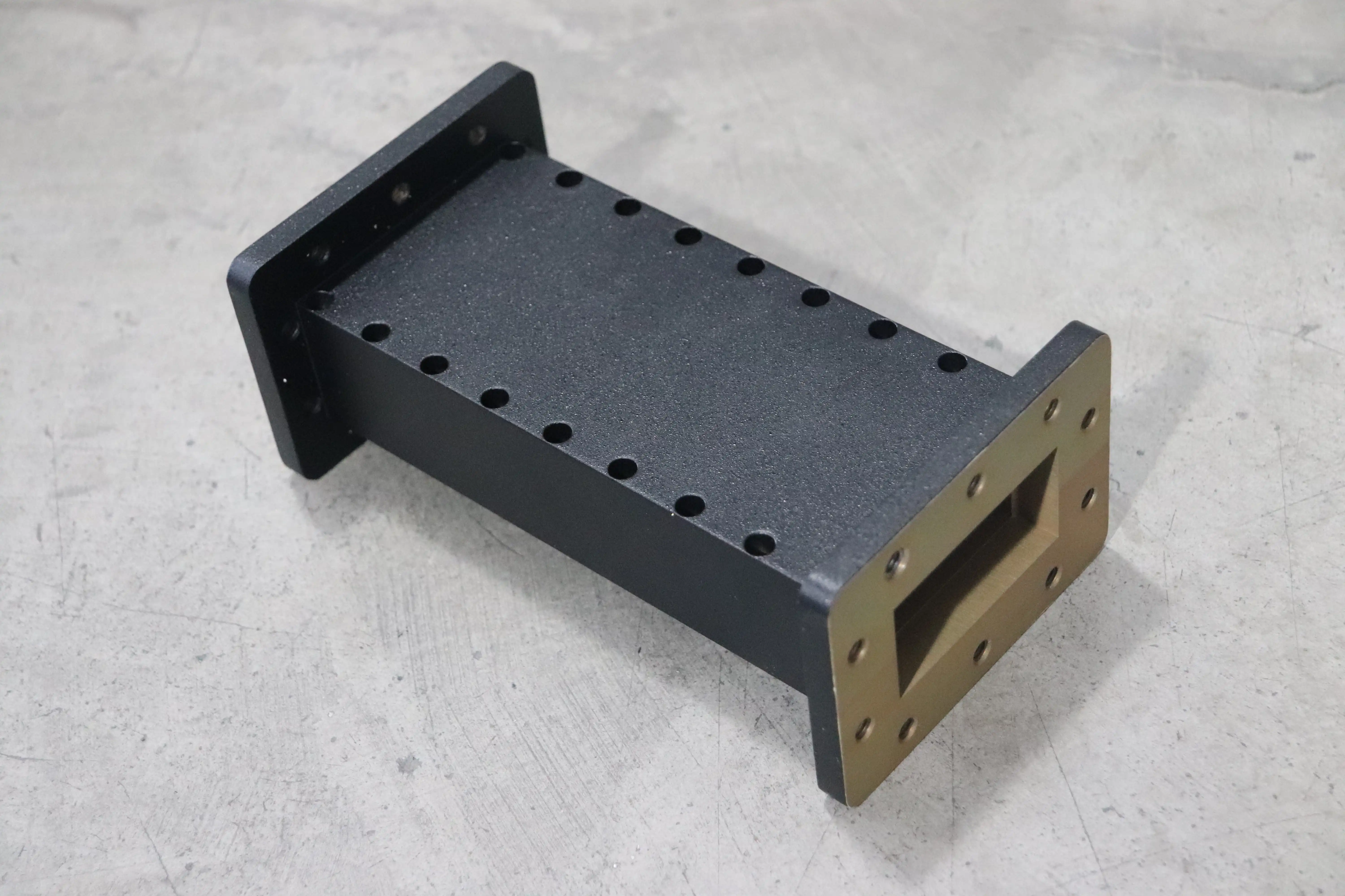
The change from passband to stopband is controlled by where the cutoff frequency is placed. We usually set the cutoff for Ka-band uplink systems that send at 29.5 to 30 GHz at 35 GHz. This gives us a 5 GHz guard band and makes sure that second harmonic rejection starts at 59 GHz. To keep the total link budget, insertion loss in the passband must stay below 0.4 dB. This means that surface finishes must be better than 0.8 microns Ra and manufacturing errors must be within ±0.025 mm. Specifications for stopband attenuation usually call for 70 dB at the second harmonic. This is achieved with multi-section systems that have five or more impedance-stepping elements.
Material Selection and Manufacturing Techniques
The choice of materials has a big effect on both how well they work electrically and how reliable they are in the long run. Aluminum 6061-T6 is easy to work with and has enough conductivity for most uses. Oxygen-free copper, on the other hand, has 8% less insertion loss for the most demanding links. A layer of 3 to 5 microns of silver plating over copper surfaces gives you low loss and protection from oxidation. Our production methods are ISO 9001-certified and include CNC milling with an accuracy of ±0.01 mm, electroless nickel underplating, and then final silver deposition. These methods make sure that the performance stays the same from one production run to the next. This is very important for satellite projects that need matched filter sets for phased array ground stations.
Simulation-Driven Optimization
We use HFSS full-wave electromagnetic solvers to make models of whole filter systems, which can include mounting hardware and flange contacts that can cause unwanted resonances. Before making a physical prototype, simulation lets us guess the voltage standing wave ratio across temperatures and find areas that are likely to have multiple possible multipliers. This method shortens the time it takes to build something from months to weeks, making it easy to make changes quickly to fit the frequency plans and technical range limits of each client. Our 24-meter microwave darkroom has instruments that work from 0.5 GHz to 110 GHz. This darkroom checks the accuracy of simulations and characterizes production units to make sure that S-parameters match what was predicted.
Procurement Considerations for Waveguide Low Pass Filters in Ka-Band Applications
To choose the best waveguide low-pass filter supplier, you need to look at both their professional skills and their business practices, which can affect the total cost of ownership and the time it takes to complete the job. When making this choice, procurement engineers should use a broad structure.
Technical specification alignment is the most important thing to think about. In addition to basic frequency and power handling requirements, you should also check to see if the supplier can meet the environmental requirements that are important for your application, such as MIL-STD-810 for defense systems or ECSS standards for space hardware. Ask a third party to do tests that show how well the product works in conditions that are similar to your working setting in terms of temperature cycling and vibration profiles. Customizing flange types, like UG-387/U for standard lab equipment or specialized CPR waveguide for spacecraft integration, shows that manufacturing is flexible enough to adapt to changing system architectures.
Quality certifications for a waveguide low pass filter are an objective way to show that a process is mature. With ISO 9001 approval, you can show that you have written down processes for controlling design, keeping an eye on production, and taking corrective action. RoHS compliance makes sure that materials meet environmental rules so that business satellites can be sent to markets in Europe and Asia. Every year, our labs make sure that their testing is still in line with national standards. This way, we can be sure that the measurements we use to confirm filter performance data are accurate.
Delivery times and minimum order amounts have a direct effect on the plans for programs and the costs of keeping inventory. Standard catalog designs usually ship in two to four weeks, but fully customized solutions can take eight to twelve weeks for design changes, prototype testing, and making the production tools. Make it clear if the lead times given include environmental testing and documentation packages. Different manufacturers have different minimum order numbers, which can range from a single prototype unit to more than 50 units for production. Suppliers who already have production lines set up for similar designs can often handle smaller amounts cost-effectively.
When a system is being put together or a problem is being fixed, technical support skills become very useful. Assisting with insertion loss budgeting, flange fit checking, and temperature management planning requires applications engineers who know what they're doing. Support after delivery, which includes guarantee coverage, usually lasts between 12 and 24 months. However, some companies offer longer programs for long-lifecycle satellite programs.
Case Studies and Practical Applications of Waveguide Low Pass Filters in Ka-Band Satellites
Real-life examples show how choosing the right waveguide low-pass filters can lead to measurable system improvements. These examples show common problems that buying teams face and how they can solve them.
A North American aerospace integrator working on next-generation Ka-band satellite stations had its first design turned down by the FCC during approval tests because it didn't have enough second harmonic suppression (measuring only 52 dB instead of the needed 60 dB). The analysis showed that their cavity filter method had resonances that changed with temperature, which hurt stopband performance above 60°C. We worked together to come up with a seven-section corrugated waveguide filter that is stable from -40°C to +85°C and has an insertion loss of 0.35 dB and a second harmonic rejection of 72 dB. With an 11-dB margin, the revised terminal passed approval, and the program moved on to production without any delays.
For a 32-element Ka-band phased array antenna, a European satellite operator needed matched filter sets to improve the infrastructure of a ground station. Matching the amplitude and phase across all 32 channels was very important for getting accurate beamforming. Off-the-shelf filters had insertion loss changes of ±0.8 dB and phase changes of ±15°, which wasn't good enough for their 0.3° beam aiming need. Our manufacturing method, which was checked using statistical process control of key measurements, produced 32 units that were perfectly matched in terms of amplitude (0.15 dB) and phase (±4°) at 30 GHz. The antenna that was made had the right amount of gain and sidelobe reduction, which let the user get 40% more data through their system than before.
When research groups are making experimental millimeter-wave satellite communication systems, they often need filters that don't fit the usual criteria. A university lab that was looking into propagation effects at 38 GHz needed a low-pass filter that could pass between 38 and 40 GHz but block a test beacon at 45 GHz by 80 dB, which is an unusually steep rolloff. This couldn't be done with standard designs because the passband noise would be too high. We used optimization methods to make a mixed design that combines corrugated and waffle-iron layouts. At 45 GHz, it had 0.6 dB of insertion loss, 0.2 dB of ripple, and 82 dB of rejection. Their campaign to measure propagation went as planned thanks to the custom solution, which gave data to the ITU's models of atmospheric attenuation.
Conclusion
Waveguide low pass filters are an important part of Ka-band satellite transmission systems, which is a developed technology that is always getting better. They are the best choice for demanding military and defense uses because they can handle more power, stay stable at high temperatures, and reject harmonics. A successful procurement relies on clearly defining requirements, evaluating suppliers' technical skills, and paying close attention to quality standards and support services. The case studies show how choosing the right filters can keep systems from having to be redesigned, which can be expensive, and still help them meet tough performance goals.
Frequently Asked Questions
What frequency ranges do Ka-band waveguide filters typically cover?
Ka-band ranges from 26.5 GHz to 40 GHz. Uplinks to satellites usually use 27.5 GHz to 31 GHz and downlinks 17.7 GHz to 21.2 GHz. For these uses, waveguide low-pass filters usually have cutoff frequencies between 32 and 38 GHz. These frequencies let the main uplink band through while reducing second harmonics that show up above 55 GHz. Longer bands can be added to custom designs for military MILSATCOM or experimental systems.
How does insertion loss affect satellite link budgets?
Each 0.1 dB of insertion loss at the output of the high-power amplifier means that less power is being sent out into the environment. In a 1-watt Ka-band uplink, a 0.5 dB loss means 11% less power, which could mean you need a bigger amplifier to make up for it. When you use good waveguide filters, you can keep the insertion loss below 0.4 dB. This keeps the link margin for rain fade and atmospheric absorption.
Can waveguide filters handle the power levels in satellite uplinks?
Standard models can easily handle 50 to 200 watts of continuous wave power, while high-power models can handle 500 watts or more by using larger cross-sections and dry nitrogen to keep the pressure up to keep the voltage from dropping. For burst radar uses, the peak power handling can go over 10 kilowatts with the right design changes, such as rounded internal corners to lower field concentration.
What testing validates filter performance for space applications?
To make sure they work with high-power transponders, space-qualified filters are put through random vibrations according to NASA-STD-7001, thermal vacuum cycling, and passive intermodulation testing. Long-term dependability in vacuum is ensured by helium leak detection for hermetic seal verification. Our testing procedures copy these qualification sequences to give flight-history confidence for adding payloads to satellites.
Partner with ADM for Your Waveguide Low Pass Filter Requirements
Advanced Microwave Technologies Co., Ltd has been designing waveguides for the world's most difficult Ka-band satellite systems for more than 20 years. As a well-known company that makes waveguide low pass filters, we mix precise production with application knowledge to make parts that solve your harmonic suppression problems. Our ISO 9001-certified factories and 24-meter anechoic measurement room (covering 0.5 to 110 GHz) make sure that every filter we sell meets the published specs and can be traced back to its source.
It's our understanding that satellite programs work on tight plans and won't stand for poor performance. Our technical team works directly with your engineering staff to recommend the best filter configurations, check the accuracy of integration methods, and give you measured S-parameter data for your system models. Our manufacturing freedom lets us handle prototypes all the way up to production numbers, so you can get catalog designs shipped within weeks or fully customized solutions for unique frequency plans. You can email our application engineers directly at craig@admicrowave.com to talk about your specific Ka-band filtering needs and get full technical offers that will help you make your purchasing decisions.
References
1. Matthaei, G. L., Young, L., & Jones, E. M. T. (1980). Microwave Filters, Impedance-Matching Networks, and Coupling Structures. Artech House Publishers.
2. Levy, R., & Cohn, S. B. (1984). "A History of Microwave Filter Research, Design, and Development." IEEE Transactions on Microwave Theory and Techniques, vol. 32, no. 9, pp. 1055-1067.
3. Craven, G. F., & Skedd, R. (1995). "Evanescent-Mode Waveguide Filter Design for Millimeter-Wave Applications." IEE Proceedings - Microwaves, Antennas and Propagation, vol. 142, no. 4, pp. 293-298.
4. Rauscher, C., & Willing, H. A. (2002). "Simulation and Measurement of High-Power Waveguide Components for Satellite Communication Systems." International Journal of RF and Microwave Computer-Aided Engineering, vol. 12, no. 5, pp. 410-422.
5. Cameron, R. J., Kudsia, C. M., & Mansour, R. R. (2007). Microwave Filters for Communication Systems: Fundamentals, Design, and Applications. Wiley-Interscience.
6. Rosenberg, U., & Beyer, R. (2018). "Compact Waveguide Low-Pass Filters with Sharp Cutoff Characteristics for Ka-Band Satellite Payloads." IEEE Microwave and Wireless Components Letters, vol. 28, no. 3, pp. 201-203.