End Launch or Right Angle Waveguide to Coaxial Adapter?
When building or upgrading a high-frequency RF system, one of the most practical questions engineers face is whether to use an end launch or a right-angle waveguide to coaxial adapter. The short answer: it depends on your spatial layout, frequency band, and power requirements. End launch adapters deliver inline signal transition with broader bandwidth and lower VSWR, making them preferred for precision lab and antenna feed applications. Right-angle adapters redirect the signal path by 90 degrees, saving space in dense assemblies. Both serve the same fundamental purpose — bridging waveguide and coaxial interfaces without compromising signal integrity.
Understanding Waveguide to Coaxial Adapters
What These Adapters Actually Do
A waveguide to coaxial adapter is a passive electrical part that changes RF energy between two very different ways of sending it. In TE10 mode, signals are sent through rectangular waveguides, and in TEM mode, they are sent through coaxial lines. The internal probe of the adapter pairs electromagnetic energy across this modal barrier with almost no radiation loss or reflection.
These parts are rated for certain frequency ranges, from L-Band (1–2 GHz) to W-Band (75–110 GHz). They are defined by their VSWR, insertion loss, and power-handling ability. Most of the time, an adapter with good design has VSWR below 1.25:1 and insertion loss below 0.3 dB across its full maximum bandwidth.
End Launch vs. Right Angle: The Core Distinction
The form of these two types directly affects how they conduct electricity and how well they work with other parts. In terms of structure, these are the ways they are different:
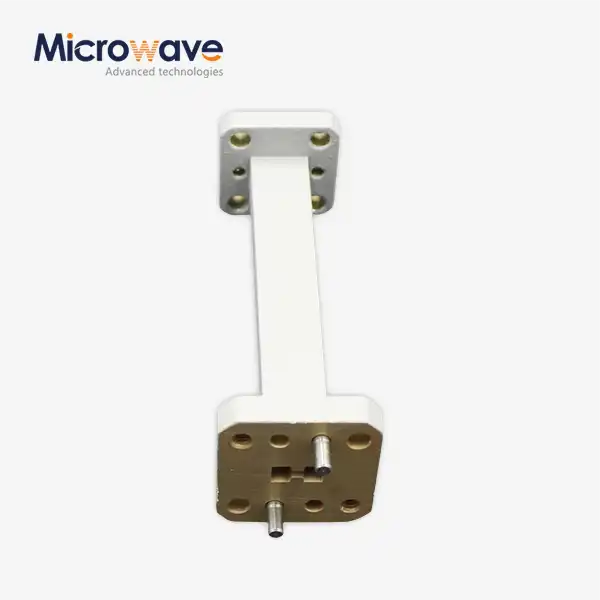
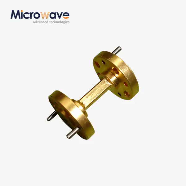
- End Launch (Inline) Adapter: The coaxial port comes out of the waveguide's wide side, which is parallel to the direction of signal propagation. This shape allows for a wider bandwidth, better impedance matching, and lower VSWR—usually less than 1.20:1 for precision-grade units. It is usually picked for test and measurement setups, feed chain assemblies, and systems that can route signals in a straight line.
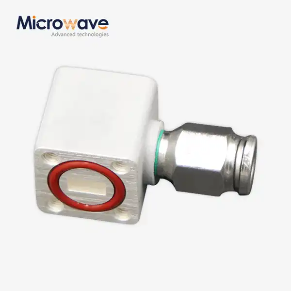
- Right Angle Adapter: The coaxial port comes out in a straight line from the waveguide axis. To get the best standing wave reduction across the target band, the back-short space behind the probe needs to be fine-tuned. This design is small and works well in structures with limited room, radar front-ends, and multi-port phased array panels where an inline shape wouldn't work.
Both configurations are available in standard waveguide sizes like WR-28, WR-42, WR-90, WR-112, WR-137, and others. The connector ports come in SMA, N-Type, 2.92 mm, and 2.4 mm, depending on the application's highest frequency limit.


End Launch vs. Right Angle: Performance and Application Comparison
Electrical Performance Metrics
To choose between the two types of waveguide-to-coaxial adapters, you need to look at electrical performance factors that can be measured. The following differences are well known in the RF and microwave industries:
- VSWR: Because the probes are oriented in a straight line, end-launch designs always have smaller VSWR over wider bandwidths. It's important to be precise with back-short tuning on right-angle designs, and the VSWR may be higher at the band ends.
- Insertion Loss: In standard setups, both types aim for less than 0.3 dB. End-launch units work a little better at higher frequencies because there are fewer gaps in the cavities.
- Bandwidth: End launch adapters often have more than 20% extra bandwidth. Most of the time, right-angle versions work best with smaller operational windows.
Industry Application Scenarios
A lot of the demand for both kinds of adapters comes from the defense and aircraft industries. When it comes to phased array radar devices, right-angle adapters let you set up a lot of ports in a small space. In satellite ground station feed assemblies, end-launch designs keep the signal-to-noise ratio stable at the important switch point where the antenna meets the low-noise block downconverter. Precision adapters are being used more and more in 5G mmWave base stations and other communication equipment to connect antenna elements to RF front-end modules with little signal loss.
How to Choose the Right Waveguide-to-Coaxial Adapter for Your Needs
Decision Criteria for Procurement Teams
Picking the right adapter isn't just a technical matter; it has a direct impact on how reliable the system is, how long it takes to integrate, and the total cost of ownership. Before sending out a purchase order, procurement engineers should look at the following:
- Frequency band and waveguide size: Make sure that the WR number matches your working frequency exactly. When waveguide cutoff frequencies are not met, there is a lot of data loss.
- Connector interface: SMA works successfully up to about 18 GHz; 2.92 mm goes up to 40 GHz; and 2.4 mm goes up to 50 GHz. Choose based on the highest frequency that your machine can handle.
- Power handling requirement: N-Type or 7/16 DIN connections are better than SMA for high-power transmit lines (above 500 W average) because they have better dielectric breakdown margins.
- Physical envelope: Check to see if the installed assembly lets you route in a straight line. A right-angle adapter is usually the only choice when the chassis depth is less than 30 mm.
- Environmental rating: For systems that will be used in the field, at sea, in the air, or in the air, make sure that the adapter's material (aluminum or copper) and surface treatment meet the humidity and temperature requirements.
These criteria allow procurement managers to quickly sort through seller catalogs and cut down on the time it takes to respond to RFQs. During the pre-order step, ADM's engineering team can help match specifications by providing swept VSWR and insertion loss data from calibrated VNA readings.
Procurement and Supply Considerations
What to Look for in a Qualified Supplier
There are a lot of different companies that make waveguide-to-coaxial adapters, and the quality of their parts varies a lot. When buyers are looking at providers, they should make sure that they have ISO 9001:2015 certification, recorded test data per unit, material traceability, and RoHS compliance to make sure they follow global regulations.

ADM makes waveguide-to-coaxial adapters for a variety of waveguide bands and connection types. They do this with the help of their own measurement equipment that covers frequencies from 0.5 GHz to 110 GHz. There is a Certificate of Conformance and swept RF test data with every unit that is delivered. With quick development before full production commitment, you can get custom designs like non-standard flange patterns, hermetic sealing, and specialty plating like gold-over-silver.
It's important to note that ADM sells High Power Waveguide Isolators along with these waveguide-to-coaxial adapters. These isolators protect transmitter stages from reflected power, which is a common need in high-power coaxial-fed systems. They can handle up to 1,000 W of forward power, 20 dB of typical isolation, and 0.3 dB of insertion loss over an 800 MHz bandwidth. They are made of aluminum and copper and can work in temperatures ranging from -40°C to +70°C. They fit naturally into the same feeder systems where adapters are used.
Benefits and Future Trends of Waveguide to Coaxial Adapters
Selecting a well-known adapter will pay off in many ways after the initial installation. Precision-made units cut down on the number of times they need to be tested again during system integration. They also lower the risk of passive intermodulation in sensitive receive paths and increase service intervals by keeping contact integrity stable during thermal cycling.
In the future, millimeter waves will be used in 5G New Radio (FR2 band, 24.25–52.6 GHz) and next-generation LEO satellite systems. This will increase the need for adapters with ratings of 28 GHz, 39 GHz, and higher. New ways of making things, like CNC-machining oxygen-free copper bodies and electroforming silver plating to MIL-DTL-45204, are making it possible for smaller size tolerances at these frequencies. A 10-micron machining error can change the harmonic frequency by several hundred megahertz.
For B2B procurement teams planning multi-year sourcing strategies, partnering with a maker that offers scalable output, technical co-development, and documented quality systems is a real way to lower their risk when planning multi-year buying strategies.
Conclusion
Both end launch and right-angle waveguide to coaxial adapters both work to move signals from one type to another, but they do so in different shapes. End launch setups are the best choice for test-heavy and feed-chain applications because they have better broadband performance and lower VSWR. Right-angle designs make the installation space small, which is very important in radar and avionics assemblies with a lot of parts. The best choice depends on the frequency band, the device's physical limitations, the power level, and the reliability standards your application needs. When you buy the right adapter from a qualified, approved maker, you can be sure that it will work well with your system for a long time.
FAQ
What is the typical insertion loss for a waveguide to coaxial adapter?
Over the full frequency range, most standard precision adapters have an insertion loss of less than 0.3 dB. If the millimeter-wave frequency is higher than 40 GHz, this number may go up a little, but it depends on the connection type and surface finish.
Can I use an SMA connector for high-power transmit applications?
When used continuously at microwave frequencies, SMA connectors can handle about 0.5 W to a few watts. To keep the dielectric from breaking down, N-Type or larger coaxial connections should be used for send lines with average power levels above 100 W.
How does back-short distance affect right-angle adapter performance?
A resonant tuning condition is created by the back-short cavity behind the probe in a right-angle adapter. The center frequency of the impedance match moves when this distance is changed. To get the desired VSWR across the goal band, this hole must be machined with great care.
Does ADM offer custom flange patterns for legacy system integration?
Yes, ADM can make custom flanges with half-height WR, double-ridge, and proprietary metric patterns that work with old or unique systems without the need for extra hardware.
Request a Quote from ADM — Your Trusted Waveguide to Coaxial Adapter Manufacturer
ADM makes high-quality waveguide to coaxial adapters and has been making them for more than 20 years. They are ISO 9001:2015 certified and have been tested in-house up to 110 GHz. Our engineering team is ready to help you with your project from the beginning to the end, whether you need standard stock units or fully customized OEM solutions for 5G, defense, or satellite deployments. You can talk about your needs right away by emailing craig@admicrowave.com.
References
1. Pozar, D. M. — Microwave Engineering, 4th Edition. Wiley, 2011.
2. Marcuvitz, N. — Waveguide Handbook. MIT Radiation Laboratory Series, McGraw-Hill, 1951. Reprinted by IET, 1993.
3. Montgomery, C. G., Dicke, R. H., & Purcell, E. M. — Principles of Microwave Circuits. MIT Radiation Laboratory Series, 1948. Reprinted by IET, 1987.
4. IEEE Std 287-2007 — IEEE Standard for Precision Coaxial Connectors (DC to 110 GHz). IEEE, 2007.
5. Collin, R. E. — Foundations for Microwave Engineering, 2nd Edition. Wiley-IEEE Press, 2001.
6. Wadell, B. C. — Transmission Line Design Handbook. Artech House, 1991.