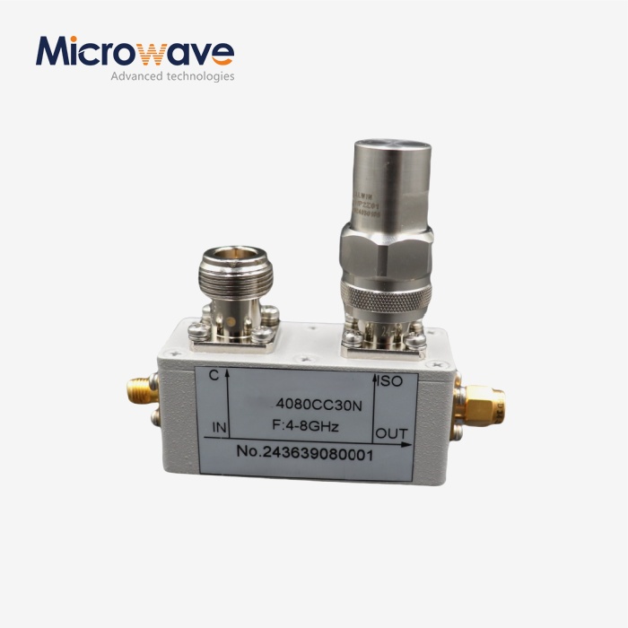
Waveguide Attenuators Explained: VSWR, Flatness, and Power Ratings
Waveguide attenuators are precision passive components used in microwave and RF systems to reduce signal power by a defined amount while keeping reflections low and maintaining consistent performance across frequency bands. Whether you're building a radar system, setting up a satellite ground station, or calibrating a test bench, understanding how these components work—and what separates a good one from a poor one—can save you real time and money. This article breaks down the key specs you should know: VSWR, frequency flatness, and power ratings.
Understanding Waveguide Attenuators: Fundamentals and Types
How They Work
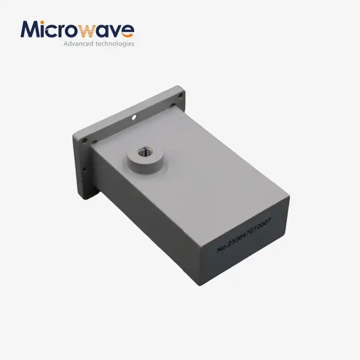
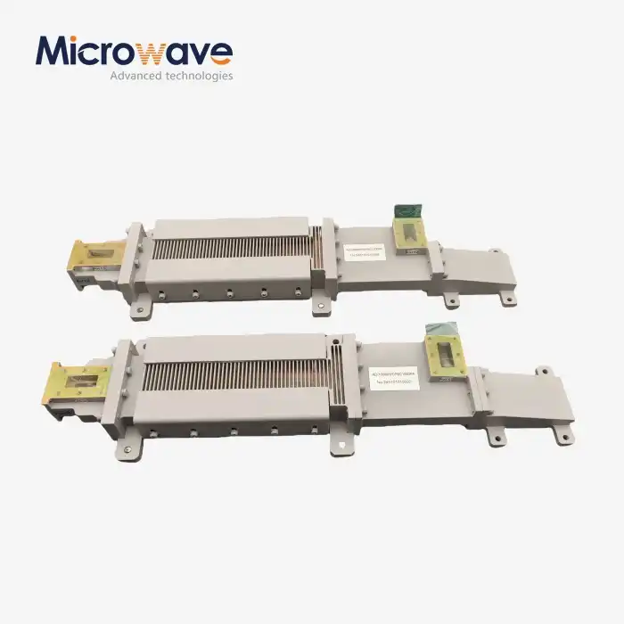
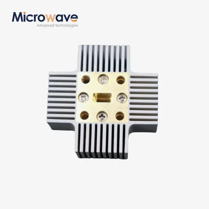
A waveguide attenuator lowers the power of a microwave signal by adding a resistance element inside the waveguide channel. This is usually a lossy film or card. The electromagnetic wave that is coming in is partly absorbed, but the information that is still there keeps going forward at a lower level. Based on waveguide size (e.g., WR-90 for X-band, WR-28 for Ka-band), operating frequencies can be anywhere from 1 GHz to 110 GHz or higher.
Fixed vs. Variable Types
Fixed attenuators have a set attenuation value, like 3 dB, 6 dB, 10 dB, or 20 dB. They are best when repeatability and ease of use are important. Rotating vane or step attenuators are examples of variable attenuators. They can be changed over a set range, which makes them perfect for test setups and systems that need to control power dynamically. Each type has pros and cons when it comes to cost, complexity, and how stable the adjustment is over time.
Waveguide vs. Coaxial Attenuators
Waveguide-based systems work better than cable ones at high frequencies, especially above 18 GHz. Dielectric losses are added by coaxial attenuators, and they get worse as the frequency goes up. This problem is completely avoided by waveguide attenuators that use hollow metal tubes for transmission. They can also handle more power without getting worse when heated, which is why they are the usual choice in radar and satellite send chains that use a lot of power.
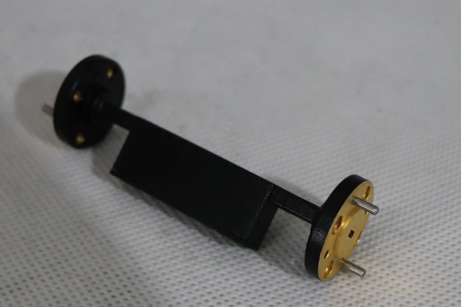
Critical Performance Dimensions: VSWR, Flatness, and Power Ratings
VSWR and Signal Integrity
The voltage standing wave ratio (VSWR) shows how much of a signal is being reflected back from a part instead of going through it. It is thought that a VSWR of 1.0:1 is perfect. In real life, good waveguide attenuators usually get VSWR values of 1.15:1 or better across their rated band. When VSWR is high, like above 1.5:1, a lot of power is returned, which can damage transmitter stages and mess up readings.
Frequency Flatness
Frequency flatness is a measure of how stable the attenuation value is over the whole operating bandwidth. A 10 dB attenuator with a stability rating of ±0.5 dB will give you between 9.5 dB and 10.5 dB across all of its frequency range. When smoothness isn't right, system behavior is hard to predict. Tight flatness specs—often ±0.3 dB or better—must be met for broad uses like EW systems or multi-channel test sets.
Power Ratings: Average vs. Peak
Power numbers tell you how much RF energy the attenuator can take in without breaking. Peak power handles short pulses, which are important in radar and pulsed systems. Average power rating handles continuous power. The average power rating of a typical attenuator might be 2W, but it can handle 200W peak power for microsecond cycles. Field failures often happen because these values are not used correctly, so always check both numbers against your system's duty cycle.
How to Choose the Best Waveguide Attenuator: Key Decision Factors
Attenuation Value and Accuracy
First, figure out what amount of reduction you need and how tightly it needs to be held. Most fixed attenuators have tolerances of ±1 dB, but precision models have tolerances of ±0.5 dB or better. If your system depends on measured power levels, like test and measurement software, then a smaller range has a direct effect on how accurate the results are. Always check the datasheet to see if it talks about tolerance at a single frequency or for the whole band.
Material Quality and Durability
The base is usually made from metal or brass that has been machined, and the insides are plated with silver or gold to make them more resistant to corrosion. Coatings that don't rust and sealed flange connections are important for outdoor or defense uses. Not just RF specs that look good on paper are enough for parts that are exposed to humidity, salt air, or big changes in temperature. They need materials that will last. You can directly ask any waveguide attenuators supplier about this.
Adjustable vs. Fixed: The Real Trade-Off
Here are the main things you should think about when choosing between these two setups:
- Fixed attenuators are cheaper, don't need to be maintained, and work the same way every time, even after years of use. They work great for RF systems on production lines where the power level is set ahead of time.
- Variable attenuators let you change the level of attenuation on the fly, which is great for development labs, antenna test ranges, and signal simulation setups. They are more expensive, though, and need to be calibrated more often.
- Step attenuators split the difference—separate attenuation steps (like 1 dB, 2 dB, and 4 dB parts) give you more options at a lower cost than designs that are fully flexible.
Picking the right type isn't just a matter of technicality; it also affects how often you need to do upkeep and how much it will cost you in the long run. Talk to your supplier about your duty cycle and how often you want to make adjustments before you commit to a configuration.
Applications and Benefits of Waveguide Attenuators in Industry
Key Application Areas
Waveguide attenuators are used in many different systems and industries. Here are some of the most common launch situations:
- Radar systems: These are used to keep receiver front ends safe during bursts of transmission and to model target returns at controlled power levels while testing the system.
- Satellite communications: For satellite communications, make sure that the uplink power is managed in ground stations and that the amplifier chains work in linear regions.
- Test and measurement: Give network analyzers standardized signal levels, amplifier gain tests, and radio range work.
- Telecom infrastructure: For telecom infrastructure, you need to manage the flow of power in waveguide-fed antenna systems, especially at millimeter-wave frequencies (26 GHz, 28 GHz, and 39 GHz bands).
All of these uses need power reduction that is reliable, stable, and low in reflection over a wide range of demanding frequency ranges.
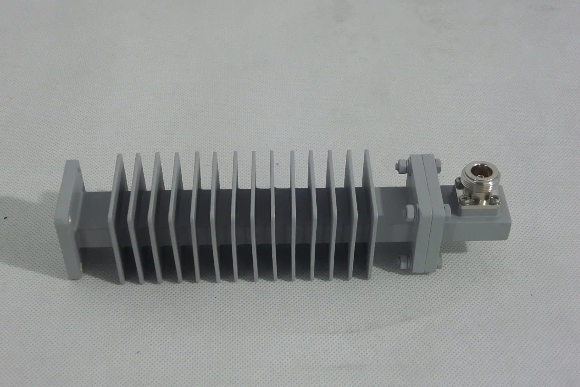
A Practical Example
A microwave test lab had to check the output power of a Ka-band amplifier without overloading the spectrum analyzer's input. They cut the signal cleanly without adding measurement error by adding a 20 dB fixed reduction with VSWR ≤ 1.15:1 and flatness ±0.4 dB. They were able to confidently figure out the attenuator's true output power thanks to its accurate datasheet. This shows how well-specified parts directly support reliable results.
Trusted Suppliers and Procurement Tips for Global Buyers
Evaluating Supplier Credentials
Not every company that sells RF components has the manufacturing experience to back up what they say on their datasheets. When looking for precision microwave parts, it's best to find suppliers whose methods are written down, whose calibration can be tracked, and who offer real expert help. The global RF and microwave component market knows ADM (admicrowave.com) for selling tested, specification-verified parts with clear documentation.
Pre-Purchase Checklist
Do these things before you place an order, especially if it's a big one:
- Verify the full datasheet: Read the whole datasheet and make sure that the VSWR, insertion loss tolerance, power rate (average and peak), and working temperature range are all clearly written.
- Check flange compatibility: Make sure you know if you need UG, CPR, or special flanges to match the waveguide hardware you already have.
- Request a test report or calibration certificate: For high-precision or high-power uses, ask for a test report or calibration certificate.
- Assess delivery lead times: Find out how long it will take to deliver and if there are any in stock for your unique waveguide band.
If you do these things before you finalize an order, you can avoid mistakes that cost more to fix than the part itself.
Conclusion
Waveguide attenuators seem easy to understand, but they are actually very hard to build. VSWR, frequency flatness, and power handling are the three most important measures that tell you whether your system works as planned or gives you problems that you'll have to spend weeks figuring out. You are in a much better position if you choose the right type, make sure the specs match your needs, and work with a supplier who can back up their datasheets with real test data. If you know what you need, you can make the right choice, whether it's a 3 dB fixed unit or a precision variable design for a wideband test setup.
FAQ
What is a typical VSWR value for a quality waveguide attenuator?
A VSWR of 1.15:1 or better is achieved by most well-made fixed attenuators across their stated frequency band. Values above 1.3:1 mean that the impedances don't match, which can cause the signal to bounce, which can be a problem in sensitive receiver chains or well-calibrated test setups.
What is the difference between average power and peak power ratings?
The divider can handle a certain amount of constant RF power, which is called its "average power." Peak power is used for pulsed devices, which have small bursts of much higher energy. For radar and pulsed microwave applications, both numbers are very important. Most of the time, thermal or electrical failure happens when you use an attenuator in a burst system without taking peak power into account.
How does frequency flatness affect system measurements?
If an attenuator's attenuation changes a lot across its band, say by ±2 dB, then any measurement of broadband will be off. When used for testing and measuring, ±0.5 dB or tighter is usually needed to keep the accuracy of the measurements.
Can I use a coaxial attenuator instead of a waveguide type at millimeter-wave frequencies?
Most of the time, no. Above 18 GHz, dielectric and connector losses in coaxial attenuators increase, which weakens the signal. These frequency ranges are designed to work best with waveguides, which also handle power better and have lower return loss.
Get Precision Waveguide Attenuators From ADM
ADM gives engineers and sourcing teams around the world RF and microwave passive components that have been carefully tested. ADM is a reliable company that makes and sells waveguide attenuators. They have both fixed and variable attenuator designs for a number of waveguide bands, and their VSWR performance, power levels, and flatness specs have all been checked. There is reliable documentation for every part that comes with it. You can send your technical needs to craig@admicrowave.com to talk about your application and get a price right away.
References
1. Pozar, D. M. — Microwave Engineering, 4th Edition. Wiley, 2011.
2. Montgomery, C. G., Dicke, R. H., & Purcell, E. M. — Principles of Microwave Circuits. MIT Radiation Lab Series, McGraw-Hill, 1948.
3. Vendelin, G. D., Pavio, A. M., & Rohde, U. L. — Microwave Circuit Design Using Linear and Nonlinear Techniques. Wiley, 2005.
4. IEEE Standard 287 — IEEE Standard for Precision Coaxial Connectors (DC to 110 GHz). IEEE, 2007.
5. Collin, R. E. — Foundations for Microwave Engineering, 2nd Edition. IEEE Press / Wiley-Interscience, 2001.
6. Laverghetta, T. S. — Handbook of Microwave Testing. Artech House, 1981.


_1733809032116.webp)