How Much Power Can a High Power Waveguide Circulator Really Handle?
A high power waveguide circulator is a passive, non-reciprocal ferrite device that routes RF energy in a single direction through sequential ports while blocking reflected signals from returning to the source. Depending on the design and thermal architecture, these devices handle average power from hundreds of watts up to several kilowatts, with peak power thresholds reaching tens of megawatts in pressurized configurations. Understanding these limits is essential for engineers selecting components for radar, satellite ground stations, and industrial microwave systems where reflected energy can destroy amplifier chains.
Understanding High Power Waveguide Circulators and Their Power Limits
What These Devices Actually Do
A high-power waveguide circulator sends signals from Port 1 to Port 2, then from Port 2 to Port 3, and so on. There is no way for the signals to go backward. When used for transmitter protection, energy that is reflected because of an impedance mismatch is sent to a fake load at Port 3, which keeps the power source whole. In radar duplexers, satellite uplink systems, and klystron-driven particle reactors, this feature is a must.
Peak Power vs. Average Power Ratings
These are two different requirements that engineers need to look at separately. Peak power ratings show how resistant something is to voltage breakdown and arcing, which is very important for pulsed radar systems. During continuous wave (CW) operation, thermal endurance is based on average power ratings. It's possible for a gadget that can handle 500 kW peak power to only handle 2 kW normal power before the ferrite junction gets too hot. Make sure that both parameters fit the duty cycle of your machine at all times.
Key Specifications That Define Power Limits
For high-power ferrite circulators, insertion loss below 0.15 dB is the standard. This is because even small resistance losses produce a lot of heat at kilowatt levels. When isolation is above 20 dB, there is almost no signal loss between isolated ports. The choice of material, especially high-Curie-temperature ferrites like lithium or nickel versions, directly affects how close the device can work to its saturation point before performance starts to drop.
Critical Factors Influencing the Power Handling Capacity
Ferrite Material Saturation and Waveguide Geometry
When the field strength goes over what the ferrite material in the joint can handle, it saturates magnetically. This stops the device from working in either direction. Waveguide cross-section sizes also set a hard limit: bigger aperture waveguides, like the WR-975 used in L-band radar systems, spread electromagnetic fields out more evenly, which lets them hold a lot more power than the narrow WR-28 Ka-band structures.
Thermal Dissipation and Cooling Architecture
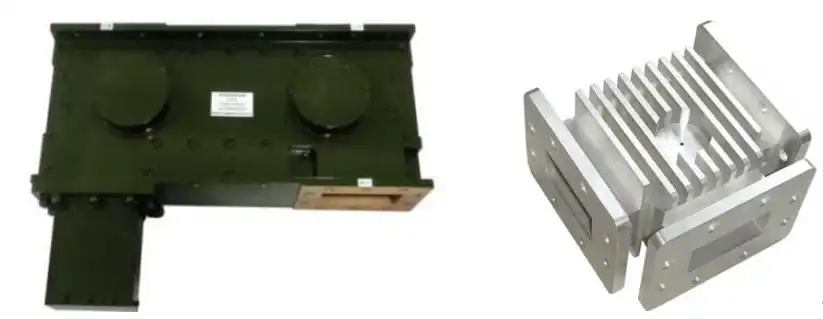
A high power waveguide circulator that handles 10 kW of average power still loses heat at the junction, even if the insertion loss is low. To deal with this, manufacturers make the bodies have liquid cooling lines cut into them, mid-range units have forced-air heatsinks, and high-thermal-conductivity housing materials like oxygen-free copper may be used. If there isn't enough cool air flowing through the ferrite, the temperature rises toward the Curie point. At this point, magnetic saturation detuning can't be undone while the device is running.
Frequency Band and Power Thresholds
As the working frequency goes up, the power handling goes down. An S-band circulator (2–4 GHz) can usually handle several kilowatts of power on average, but a Ka-band unit (26.5–40 GHz) might only be able to handle tens of watts because the waveguides are smaller and the conductors are closer together. When defining parts for high-frequency satellite communication lines and millimeter-wave sensing systems, engineers have to take this inverse relationship into account.
Comparing High Power Waveguide Circulators and Alternatives
Coaxial circulators and high-power waveguide circulators do some of the same things, but at high power levels, their structural differences cause them to work differently.
Waveguide structures naturally have higher power density and lower conductor loss than coaxial structures. This is because they keep the electromagnetic field inside a hard metal box instead of between a center pin and an outer conductor. Above about 100 W of normal power, this physical edge becomes very important. For buying, this is where the difference is most important:
- High-power waveguide circulators handle power levels from kilowatts to megawatts as absorption loss is less than 0.15 dB, making them the best choice for radar receivers, industrial microwave heating systems, and high-power satellite uplinks.
- Coaxial circulators work well in low-power subsystems, benchtop test environments, and installations with limited space as long as the average power level stays below 100 W.
When you choose between high separation and low insertion loss, you have to make a clear trade-off. A circulator that is designed to have the least amount of insertion loss keeps the transmitter's efficiency but may only provide 20–23 dB of separation. When the separation level is higher than 30 dB, the source is better protected, but the junction loss is a little higher. The isolation number is the most important part for sensitive receiver protection apps.
Mercury Microwave is a well-known company that sells a wide range of defense pulsed radar and high-power waveguide circulators. Narda provides MIL-qualified units with test results for the surroundings that can be proven. For faster ordering, Pasternack keeps high-power waveguide circulators that are already made in stock across standard bands. ADM engineers at admicrowave.com create and make custom high-power waveguide circulators that fit specific frequency, power, and flange configurations, supported by ISO 9001:2015-certified production and testing tools that can handle signals up to 110 GHz.
Practical Procurement Considerations for High Power Waveguide Circulators
Specifications That Matter Beyond Power Rating
When purchasing something, procurement engineers should ask for the full data sheet that includes the VSWR at all ports, the operating temperature range, the flange interface standard (UBR, CPR, or custom), and the CW vs. pulsed power ratings at the duty cycle that is needed. If you only know the peak power of a high power waveguide circulator and not the average power, you don't know how well it will handle heat, which is a common reason why field failures happen.
Pricing, Lead Times, and Volume Orders
Standard band waveguide circulators in quantities of 10 to 50 units usually have lead times of 6 to 10 weeks from well-known manufacturers. Lead times can be 12 to 16 weeks if you need non-standard flanges, specialized frequency bands, or built-in dummy loads. When you buy more than 100 units, the prices usually go down by a significant amount, especially when you spread the costs of the tools out over the whole run. System integration projects can avoid schedule risk by making these words clear early on.
OEM and Customization Options
Many companies that put together defense and satellite systems need circulators that are built to exact mechanical envelope limits, specific connection orientations, or with recorded lot tracking. OEM design services from ADM include rapid prototyping for testing before full production, custom flange configurations, and detailed technical documentation packages that can be used to build larger RF subsystem assemblies.
Maximizing Reliability and Longevity in Waveguide Circulator Applications
Installation Best Practices
It is necessary to use the right pressure on flange screws. When the clamping isn't even, it bends the waveguide interface and creates reflection points that heat up the joint locally. Before turning on, always check the port orientation against the device's directional marking. Reversing the flow of power through the wrong port skips the protection function and could damage the ferrite assembly.
Routine Monitoring and Maintenance
Insertion loss is the main way to tell if an in-service circulator is healthy. A slow rise of 0.1 to 0.2 dB above the baseline is often a sign of coolant channel scaling or early ferrite degradation. For units that are cooled by liquid, checking the conductivity and flow rate of the coolant every three months stops corrosion-driven failure, which is the most common type of long-term failure seen in field service data. Record initial measures at the start of the project so that you can look at trends.
Lessons from Deployed Systems
Radar installers say that circulators that are used at 70% of their rated average power limit and with enough water flow usually last longer than 10 years. When units are pushed to 90% of their rated average power without any room for changes in ambient temperature, they start to break down faster within 3–5 years. In defense and satellite ground station settings, it is common for engineers to keep a 30% power derating range against the manufacturer's average power standard.
Conclusion
Power handling in high power waveguide circulators is not based on a single number on a document, but on the qualities of the ferrite material, the shape of the waveguide, and how the heat is managed. Both the peak and average power ratings must match the duty cycle, operating conditions, and environment of your system. If you match these factors properly during the procurement stage, you can avoid expensive failures in the field and make parts last much longer than ten years in radar, satellite, and industrial uses that are very demanding.
FAQ
What primarily limits the maximum power a waveguide circulator can handle?
Three things set the ceiling: the ferrite material saturation, the waveguide's physical size, and its ability to dissipate heat. When any of these is reached, the device stops working or its speed drops. When cooling is done right and the right materials are used, both the average and peak power limits are directly raised.
Are high-power waveguide circulators suitable for both radar and satellite communication systems?
Yes, but there are big differences in the details. Radar systems need to be able to handle high peak power and pulses quickly, while satellite communication links need to have low insertion loss and stable CW average power performance. Before you define, you should always check the duty cycle and frequency band.
How does insertion loss affect power handling?
At the ferrite junction, less energy is turned into heat when the insertion loss is low. At kilowatt power levels, a difference of just 0.2 dB in insertion loss causes a big rise in the thermal load. This is the reason why insertion loss should be less than 0.15 dB in high-power designs.
Why are some waveguide circulators pressurized?
Adding dry nitrogen or SF6 gas to the waveguide cavity raises the dielectric breakdown threshold. This lets the device handle more peak power without arcing. For burst radar and accelerator uses, this is the normal way to do things.
What is the typical service life of a properly maintained unit?
As long as it stays cool and works within its stated limits, the service life usually lasts longer than 10 years. Coolant channel rust and ferrite breaking from thermal shock are the main ways that things break.
Request a Custom Waveguide Circulator Quote from ADM
For more than 20 years, ADM has been making precise RF and microwave parts for users in military, satellite, and industry around the world. As long as you give us your exact frequency band, power level, and flange specifications, our research team can build a high power waveguide circulator that meets all of those needs. To talk about your needs and get a competitive quote, email us at craig@admicrowave.com.
References
1. Pozar, D. M. Microwave Engineering, 4th ed. — Wiley, 2011.
2. Helszajn, J. Ferrite Phase Shifters and Control Devices — McGraw-Hill, 1989.
3. Helszajn, J. The Stripline Circulator: Theory and Practice — Wiley-IEEE Press, 2008.
4. Montgomery, C. G., Dicke, R. H., & Purcell, E. M. Principles of Microwave Circuits — MIT Radiation Lab Series, McGraw-Hill, 1948.
5. IEEE Transactions on Microwave Theory and Techniques — "Power Handling Limitations of Ferrite Junction Circulators," Vol. 54, No. 10, 2006.
6. Collin, R. E. Foundations for Microwave Engineering, 2nd ed. — Wiley-IEEE Press, 2001.
_1733738410152.webp)