





Straight Waveguide Section Dimensions Engineers Need to Know
When specifying a straight waveguide section for high-frequency RF systems, engineers must understand that dimensional accuracy directly determines electromagnetic performance. The straight waveguide section serves as the backbone of signal transmission in radar, satellite communication, and defense applications, where even micron-level deviations in cross-sectional dimensions can result in signal reflection, increased insertion loss, and mode distortion. Understanding the relationship between physical dimensions—particularly inner width (a), height (b), wall thickness, and overall length—and operational frequency ranges ensures procurement teams select components that deliver consistent performance across mission-critical environments.
Understanding Straight Waveguide Section Dimensions: General Overview
Straight waveguide sections work like hollow metal tubes that carry electromagnetic waves with little loss. In contrast to coaxial lines, these parts need exact internal measurements to set cutoff frequencies and support certain transmission modes. Standardised WR (Waveguide Rectangular) designations define the rectangular cross-section, which makes sure that all manufacturers and systems can work together.
The Role of WR Designations in Standardization
WR labels give engineers and buying managers a common language to use. A WR-90 waveguide has an internal width of 0.900 inches (22.86 mm) and a height of 0.400 inches (10.16 mm). It is often used in X-Band applications (8.2–12.4 GHz). These common sizes, which are set by standards like EIA-RS-261 and MIL-DTL-85/3, make sure that system parts can work together. Knowing these names lowers the risk of procurement and speeds up the time it takes to integrate, especially when big projects require getting supplies from many different sources.
Material Selection and Compliance Requirements
The choice of material affects both how long something lasts mechanically and how it behaves electromagnetically. Copper and brass are better at conducting electricity than aluminum alloy, which makes them ideal for low-loss applications. Aluminum alloy is lightweight and can be used in airborne systems. Adding silver or gold plating to the surface can lower resistive losses even more at high frequencies. Buying straight waveguide sections that follow the rules for quality management (ISO 9001:2015) and the environment (RoHS) makes sure they meet the rules for defence, military, and business satellite systems.
Our manufacturing processes at Advanced Microwave Technologies Co., Ltd. are in line with ISO 14001:2015 safety rules for workers and ISO 45001:2018 environmental rules. This shows that we care about environmentally friendly output without sacrificing accuracy in measurements.
Key Dimensional Parameters Every Engineer Must Know
Straight waveguide section performance measures are directly linked to dimensional factors. To keep systems from needing expensive redesigns or losing efficiency, procurement engineers must compare these specs to the system needs.
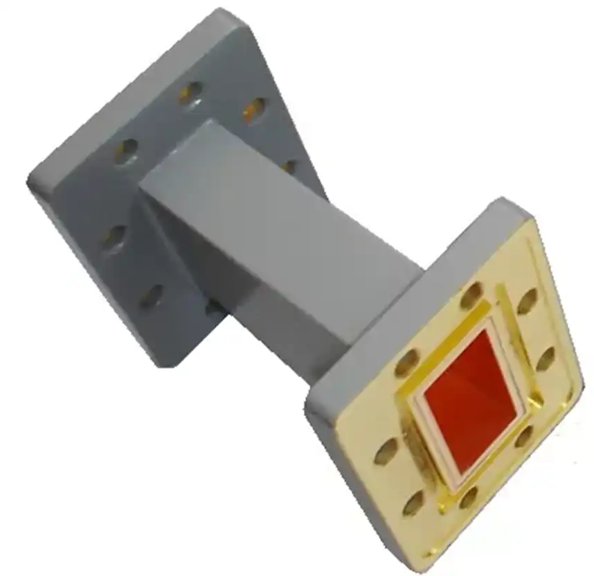
Internal Cross-Sectional Dimensions (a and b)
The cutoff frequency, below which electromagnetic waves can't travel, is set by the internal width (a). The height (b), which is usually half the width, affects how much power it can handle and how well it can reduce higher-order modes. To keep the required electrical performance, these measurements must stay within ±0.001 inches (±0.025 mm) of their given ranges. Deviations outside of this range lead to impedance mismatches, which lower the voltage standing wave ratio (VSWR).
In the 20 years we've been in the manufacturing business, we've seen that procurement teams often don't realise how much tolerance stacking matters. When several straight waveguide sections are connected in series, errors in the dimensions can cause the effective operating bandwidth to change. This is especially true for narrowband uses like Ku-Band satellite downlinks (10.7–12.75 GHz).
Wall Thickness and Mechanical Integrity
The width of the walls affects both how strong the structure is and how well it blocks electromagnetic waves. Thin walls make things lighter, but they can change the size inside when they are put under stress or when the temperature changes. For defense purposes, especially shipboard radar systems that are subject to vibration and temperature changes, walls need to be thicker and stronger mechanically. The wall thickness affects the skin depth at working frequencies, which in turn changes the way attenuation works.
Length Tolerances and Impedance Matching
When straight waveguide sections work as impedance transformers or phase shifters, they need to be very precise about their length. A length mistake of only 0.010 inches (0.254 mm) in a Ka-Band waveguide (26.5–40 GHz) can cause a phase shift of more than 10 degrees, which can make it hard for array antennas to work together. Tolerances for length must be clearly stated in procurement specs. This is especially important for phased array systems where beam direction precision depends on phase accuracy.
Interrelationships Between Dimensions and Electromagnetic Performance
The basic electromagnetic behaviour of straight waveguide sections is controlled by how accurate the measurements are. Engineers need to know about these connections in order to choose the right parts and fix problems with the performance of the whole system.
Cutoff Frequency and Mode Propagation
To find the cutoff frequency for the main TE10 mode in a rectangular waveguide, use the formula fc = c/(2a), where c is the speed of light and an is the width of the waveguide. To keep the signal stable and stop reactive power losses, operating frequencies must be at least 25% higher than this cutoff. The useful bandwidth goes up to about 95% of the next higher mode's cutoff frequency. Above that, mode competition messes up the signal.
When purchasing straight waveguide sections for multi-band systems, procurement engineers need to make sure that the dimensions meet all frequency bands. Our X-Band Feed Network designs, which are used in air traffic control radar and satellite ground stations, show how precise dimensional control lets multiple devices work at the same time across 8.2–12.4 GHz without mode interference.
Dimensional Precision and Insertion Loss
Insertion loss in straight waveguide sections is mostly caused by conductor losses, which are related to the surface resistance of the walls inside. As a result of the manufacturing process, surfaces are rough, which raises both effective resistance and insertion loss. Using high-precision cutting and electroplating reduces surface flaws so that insertion losses in X-Band uses are less than 0.01 dB per foot.
Dimensional consistency across production batches makes sure that insertion loss characteristics can be predicted. This is very important for large-scale deployments where system performance needs to stay the same. Our production methods are ISO 9001:2015-certified and use statistical process control (SPC) to keep repeatability of dimensions within certain limits.
Comparison with Alternative Waveguide Configurations
Flexible waveguides have higher insertion loss because their internal sides are corrugated, while straight waveguide sections work better. Dual-polarization operation is possible with circular waveguides, but they need mode converters to work with rectangular parts. Even though microstrip transmission lines are small, they have a lower frequency and more radiation loss. Procurement managers can find a good balance between performance, cost, and integration complexity when they know about these trade-offs.
Practical Application of Dimensional Knowledge in Procurement and Engineering
To turn dimensional specifications into decisions about what to buy, you have to balance technical needs with the ability to make the product and the cost. This part gives you useful information for choosing the right waveguide configurations.
Frequency Band Selection and Standard Dimensions
Standardized straight waveguide section dimensions match up with common frequency bands. WR-90 waveguides are usually used for X-Band systems, while WR-62 or WR-75 are used for Ku-Band systems. If you choose standard measures instead of unique designs, you'll save money on costs and time. Standard parts also gain from well-known test methods and performance records, which speed up the approval process.
Power Handling and Environmental Considerations
The amount of power it can handle relies on its internal size and frequency of operation. Higher power levels can be supported by larger cross-sections before voltage breakdown happens. Breakdown limits are also affected by things in the environment, like altitude, humidity, and temperature. When aerospace apps work at high altitudes, they need to use derating factors to account for the lower air pressure.
Sealing off the environment stops water from getting in, which lowers the dielectric qualities and speeds up rust. Pressurisation systems keep the inside of a machine dry with air or nitrogen, which makes parts last longer in harsh conditions. Environmental safety needs to be included in procurement standards for military and satellite uses.
Verification Techniques and Quality Assurance
Coordinate measuring machines (CMM) and optical comparators are two types of precise measurement tools that are used for dimension checking. VSWR, insertion loss, and frequency response are checked for accuracy with electrical performance testing in anechoic rooms or network analyzer test sets. Our 24-meter microwave lab has antennas that can measure near-field and far-field across 0.5–110 GHz, which lets us fully describe performance.
First-article inspection (FAI) for custom designs and sample testing for production runs should be part of quality assurance plans. Setting dimensional acceptance standards in procurement contracts guards against suppliers who don't meet requirements and makes sure that mission-critical applications can be tracked.
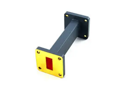
Ensuring Quality and Reliability: Choosing the Right Supplier
Choosing the right supplier has a big effect on the success of a project, especially when parts fail in ways that have big effects. Supply chains that work well are those that judge providers based on their technical skills, quality systems, and ability to help with logistics.
Evaluating Manufacturing Capabilities and Track Record
Production data and performance test reports from experienced manufacturers show that they have dimensional control. Suppliers who have their own measurement labs can give faster feedback during development stages and make sure that the standard is always the same. CNC machining, electroforming, and precision welding are just some of the manufacturing techniques that can be used to make both standard and custom configurations.
From the early 2000s until now, Advanced Microwave Technologies Co., Ltd. has sold straight waveguide sections to research centers, defense companies, and satellite service providers. Our high-tech measuring tools are qualified to work at 110 GHz and can handle strict testing procedures that confirm the accuracy of electrical and size specs. This track record gives procurement teams that are in charge of integrating complex systems peace of mind.
Compliance, Certifications, and Being Able to Track
Strong quality management systems are shown by certifications like ISO 9001:2015, RoHS compliance, and AS9100 (for aircraft uses). Material certifications and dimensional inspection reports make it possible to track parts, which is very important for defense projects that need to keep track of serialized parts. With every shipment, suppliers should include a certificate of conformance (CoC) that lists the tested and measured dimensions.
Transparency in the supply chain is part of traceability. Knowing where raw materials and subcomponents come from lowers the risks of fake parts, especially in the defence and aircraft industries where genuine parts are very important.
Delivery Timelines and After-Sales Support
Lead times depend on how complicated the parts are and how much is being made. Standard straight waveguide sections usually ship in two to four weeks, but planning, prototyping, and production for special designs can take up to eight weeks. Setting realistic deadlines during the planning phase of procurement keeps projects from running late.
After-sales support includes professional help with setup, advice on how to fix problems, and guarantee coverage. Suppliers that give development services let you test how well something works before committing to full-scale production. Our OEM services offer unique solutions with quick prototyping, and our expert engineers are there to help with problems like installation and integration.
Conclusion
When engineers and procurement professionals know the dimensions of a straight waveguide section, they can choose parts that meet strict performance standards. Dimensional accuracy has a direct effect on cutoff frequency, insertion loss, power handling, and mode propagation. These are all factors that determine how reliable a system is in radar, defence, and satellite communication. By choosing providers with proven manufacturing skills, strong quality systems, and a full testing infrastructure, you can be sure that the parts you buy will work consistently in mission-critical settings. Having this base of knowledge lets you make sure choices throughout the whole procurement process.
FAQ
1. What are the standard dimensions for common waveguide bands?
Standard straight waveguide section lengths are based on WR names set by industry standards. WR-90 is used in the X-band (8.2–12.4 GHz) and is 0.900 inches by 0.400 inches on the inside. WR-62 works with Ku-Band (12.4–18 GHz) and is 0.622 × 0.311 inches in size. With a 0.750-inch by 0.375-inch cross-section, WR-75 can handle medium frequencies. These standard dimensions make sure that parts can work with each other and make buying from different suppliers easier.
2. Why does dimensional accuracy matter in high-frequency applications?
Deviations in dimensions change the cutoff frequencies and resistance properties, which leads to signal echoes and higher insertion loss. At millimeter-wave frequencies, mistakes as small as a micron can cause big phase changes that mess up coherent systems like phased array antennas. Tight limits keep VSWR standards and bandwidth, which are very important for radar and wideband communication.
3. Can I order custom waveguide dimensions for specialized projects?
Custom straight waveguide sections are made to fit specific frequency ranges, power levels, or mechanical limitations that can't be met by standard sizes. For custom orders, engineers need to know a lot of information, like how to measure things accurately, what materials to use, and how well they need to work. Lead times are usually 4–6 weeks longer than for standard products, and prototyping services can be used to make sure the performance is good before the full production run. Because we are an original equipment manufacturer (OEM), we can make custom products for use in defence, research, and aircraft.
Partner with ADM for Precision Straight Waveguide Section Solutions.
Advanced Microwave Technologies Co., Ltd. is ready to be your reliable seller of straight waveguide sections. For more than 20 years, they have been making parts that meet strict size requirements. Our advanced testing tools and ISO-certified production methods up to 110 GHz make sure that every waveguide assembly meets your performance requirements. Our engineering team can help you with technical issues from the prototype stage all the way through production, whether you need standard WR configurations for quick deployment or custom designs for specific uses. Email craig@admicrowave.com right now to talk about your project needs and get a detailed quote that takes into account your system's frequency band, power handling, and environmental needs.
References
1. Pozar, D. M. (2011). Microwave Engineering (4th ed.). Hoboken: John Wiley & Sons.
2. Collin, R. E. (2001). Foundations for Microwave Engineering (2nd ed.). New York: IEEE Press.
3. Saad, T. S. (1971). Microwave Engineers' Handbook (Vol. 1). Dedham: Artech House.
4. Electronic Industries Alliance. (1993). EIA-RS-261: Rectangular Waveguides. Arlington: EIA.
5. Montgomery, C. G., Dicke, R. H., & Purcell, E. M. (1948). Principles of Microwave Circuits. New York: McGraw-Hill.
6. Rizzi, P. A. (1988). Microwave Engineering: Passive Circuits. Englewood Cliffs: Prentice Hall.
YOU MAY LIKE
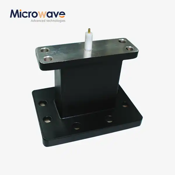 VIEW MOREEnd Launch Waveguide to Microstrip Adapter
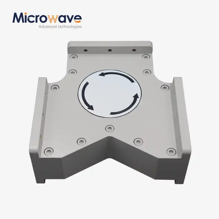 VIEW MOREHigh Power Waveguide Circulator
 VIEW MOREPlastic Flange Caps
 VIEW MORECoaxial Cable Connector
 VIEW MORECoaxial Detector
 VIEW MOREPyramid Horn Lens Antenna
 VIEW MOREWideband Double-ridged Horn Antenna
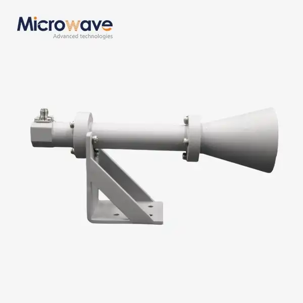 VIEW MOREDual Linear Broadband Circular Polarization Horn Antenna
