





Planar Spiral Antenna Applications in Modern Wireless Systems
Modern wireless systems that need a flat profile, a wide frequency range, and circular polarization use a planar spiral antenna. This is something that engineers use for radar, satellite communication, finding your way, navigation, telemetry, RF test systems, and UAV payloads. Along their length, the spiral arms of the antenna send out waves at different frequencies, so one aperture can work in place of several narrowband antennas. This guide was made to help people understand how the technology works, where it works best, and how to choose a supplier. It also shows how ADM helps customers in research, defense, aerospace, and telecommunications with custom designs and OEM projects.
What Is a Planar Spiral Antenna and How Does It Work?
Structure and Core Components
If you print or mount one or more conductive spiral arms on a dielectric substrate, you have a planar spiral antenna. It is a flat, wideband antenna. A feed point, radiating arms, and a balun connect the balanced arms to an unbalanced coaxial line. These are the main parts. Designers may also add a cavity, an absorber, a reflector, or a protective radome, depending on the use. There are common versions with two and four arms. Four-arm versions can improve polarization and symmetry better, but they need a more complicated feed. Printed-circuit, flexible, conformal, and miniature types are all available. Which one to choose depends on the frequency range, the space available for installation, and the amount of work that needs to be done.
Frequency-Independent Operation
A spiral antenna is in the family of traveling-wave antennas. Because it is usually Archimedean or equiangular, the spiral's shape lets different parts of it radiate at different wavelengths. The area with strong radiation is known as the "active region" by engineers. The active area moves toward the center feed as the frequency goes up. It moves outward as the frequency goes down. One antenna can handle frequency ratios of 10:1 or more and still keep its impedance and pattern shape stable because of this. You can choose between a right-hand or left-hand circular polarization sense based on the direction of the winding. In 1957, Rumsey wrote about the frequency-independent principle. Later that year, Dyson (1959) and Kaiser (1960) published early spiral designs.
Design Principles That Shape Performance
The lowest frequency that may be employed is determined by the outside diameter, since the circumference has to approach one wavelength. The largest manufacturing defects in the inner feed area and balun affect the highest frequency, so they are crucial in millimeter-wave bands. The number of revolutions, the breadth of the arms, and their separation also influence the reaction. Something operates better and more frequently depending on the loss tangent, thickness, and temperature stability of the substrate. The input impedance of a self-complementary spiral in free space is about 188 ohms. Often a wideband balun may get this down to 50 ohms. The axial ratio for circular polarization depends on the symmetry of the arm, the balance of the feed, and tolerance control. Engineers also have to consider vibration, wetness, and the durability of the couplings.

Planar Spiral Antenna Radiation Pattern and Performance
Evaluating the Full Operating Band
When customers purchase spiral antennas, I usually encourage them to look at the complete frequency spectrum, not just one. The sidelobes, cross-polarization, beamwidth, and the front-to-back ratio alter with frequency. The standard planar spiral has a broad beam which is generally 70 to 90 degrees wide. This is good for wide-angle reception and doesn't require mechanical steering. A naked spiral extends to each side. For single-directional coverage, designers incorporate a chamber with an absorber. This removes radiation from the back, but you may lose approximately 3 dB of efficiency since the absorber takes roughly half the power. Reflective cavities can recover some of that power, but the phase has to be carefully controlled so that the frequency range that may be utilized is not too limited.
Gain, Efficiency, and Axial Ratio
There are many approaches to quantify gain, directivity, and radiation efficiency. Losses in the substrate, balun, cavity, and enclosure have varying impacts on each one. The axial ratio is a measure of the quality of the polarization. A well-made spiral that is circularly polarized remains under 3 dB for much of its band. The larger the value, the more the antenna behaves like a linear antenna, which results in polarization mismatch loss. Therefore, a proper performance specification would contain restrictions on VSWR, return loss, gain, and axial ratio all simultaneously. A lot of consumers desire VSWR to be less than 2.0:1, and better grades may strive for 1.5:1. Make sure you obtain VNA sweeps, chamber pattern cuts, and polarization data from the provider. IEEE Std 149 gives forth standard procedures to test antennas.
ADM Planar Spiral Antenna Specifications
Here are the official specs for the ADM planar spiral antenna.
Feature | Specification |
|---|---|
Frequency Range | 1 GHz to 40 GHz |
Frequency Coverage | Wideband, low VSWR across range |
Impedance | 50 Ohms |
Polarization | Circular |
Gain | 3 dBi to 8 dBi |
Size | Customizable |
Weight | Light and compact |
Mounting | Easy integration with mounting kits |
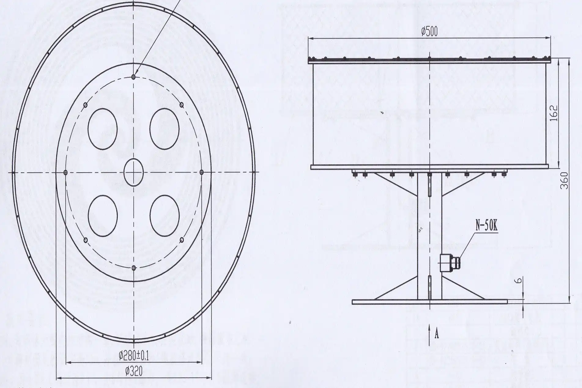
These pictures show a low-profile, wideband antenna that can be used for navigation, radar, and satellites. The materials are strong enough to last in harsh conditions, and our team can change the frequency range, materials, and size to fit any project. Our 24m Microwave Darkroom can test antennas from 0.5 GHz to 110 GHz, and all of our products are RoHS-compliant.
Modern Applications of Planar Spiral Antennas
Satellite Communications, GNSS, and Telemetry
The spiral antenna works well for satellite links because it has circular polarization. A platform that moves or tumbles can change the direction of the signal between the transmitter and receiver, and a linear antenna can lose its signal if the polarization is not aligned properly. That loss is cut down by a circularly polarized antenna, which also helps cut down on multipath interference. The flat shape fits into small spaces in low Earth orbit and CubeSat work, and circular polarization lessens the effect of Faraday rotation from the ionosphere. The benefits are the same for GNSS, telemetry, tracking, and command systems. The ADM planar spiral antenna works with satellite communication and sends signals steadily over long distances.
Radar, Electronic Warfare, and Direction Finding
Defense and space teams like apertures that cover a lot of frequencies. A spiral antenna can pick up a lot of different types of signals at once. This helps with interception, finding threats, and figuring out where something is. Its wide beam lets an airplane see from many angles without having to use mechanical steering. Fewer antennas also mean lighter frames and fewer holes in them, which is good for platforms that are sensitive to drag and UAV payloads. These kinds of parts are often put through MIL-STD-810 tests for vibration and thermal shock in avionics programs. ADM says that it can be used in shipboard systems, aviation and aerospace, unmanned aerial vehicles (UAVs), and finding your way.
RF Test Systems, Research, and Telecommunications
One antenna can be used instead of a set of narrowband units for spectrum monitoring, EMC measurement, interference identification, and signal classification. Spiral antennas are used in prototype systems, ground-penetrating radar, and remote sensing because they help keep short pulses clean and cover a wide frequency range. People who work in telecommunications use them in base stations and other systems that need to reliably handle high frequencies. Security check systems and weather monitoring are two more things that ADM can be used for. If a lab needs a frequency band that isn't common, a custom design lets the team match the antenna to the system instead of having to change the system to fit the antenna.
Where Planar Spiral Antenna Technology Is Heading
A number of trends seem likely. Smaller antennas with RF front ends, filters, low-noise amplifiers, and switches are being worked on by designers. This cuts down on size and interconnect loss. There may be more mechanical options with low-loss flexible substrates, additive manufacturing, and lightweight cavity materials. Designs that can be changed could go between bands or polarization states. Development times are already getting shorter thanks to electromagnetic simulation and automated design tools, and I think this will continue. Buyers should look for suppliers that can do both RF engineering and production. This is because a design can go from a prototype to a large-scale production run more smoothly when the two teams work together.
Planar Spiral Antenna vs. Other Antenna Technologies
Versus Helical Antennas
Helical antennas also make circular polarization, and in their axial mode, they have a lot of gain in one direction. But they are tall, which works for cylinder-shaped housings but not for flat ones. It's easier to mount a planar spiral on aircraft skins, UAV bodies, and small satellite panels because it has a thin profile. In a single flat element, it also covers a wider frequency range. There may be a better way to do a project if it needs high axial gain over a small range of frequencies and room for height. The spiral usually works better if the platform doesn't have much depth and needs to cover a lot of ground.
Versus Log-Periodic Antennas
Log-periodic antennas work well in a wide range of directions and have high gain, but they tend to be longer and linearly polarized. When both ends of a link stay in the same place, linear polarization works well. When a platform rolls or falls, it doesn't work very well. A spiral that is circularly polarized can take in any polarization with only a 3 dB loss for linear signals. It also stays flat and compact. Engineers use log-periodic units to measure high gains and add spirals when space or polarization flexibility is important for test and monitoring work. Which one to pick depends on your gain goals, the space you have, and the types of signals you expect.
Versus Patch Antennas
Patch antennas are small and simple to put together on circuit boards. A simple patch, on the other hand, only works over a small part of the frequency range, usually just a few percent of the center frequency. It can be made wider by adding stacked layers or slots, but those methods make it more complicated. With just one layer of geometry, a planar spiral antenna can reach a lot more places. A patch might be easier to use for a link with a fixed frequency, like a single GNSS band. A spiral lets you choose from different options for systems that may change frequency in the future, multi-band receivers, and signal search. Don't just compare size; also compare axial ratio, efficiency, and total system cost.
How to Select and Customize a Planar Spiral Antenna for a B2B Project?
Define Requirements and Operating Environment
Start by describing what the application is. Frequency range, VSWR limit, minimum gain, axial-ratio limit, pattern demands, impedance, connection, size, weight. Include temperature range, vibration, moisture, and radome or enclosure data. Then you may choose among two-arm, four-arm, bare planar, cavity-backed, micro and integrated-balun designs, according to your technical and commercial demands. Share your mounting plan early, as nearby metal, cables, brackets, and ground planes can affect the performance of the installation. Giving a precise brief makes it simpler to collect estimates and less likely that you'll need to redesign once the first example comes.
Evaluate Supplier Data and Quality Controls
A reliable supplier will provide you with datasheets, measured S-parameters, radiation patterns, gain and efficiency data, and axial-ratio plots. Find out how the manufacturer monitors the precision of the etching, as slight inaccuracies around the feed point might destroy performance over 18 GHz. Check the quality certificates, traceability documents, and substrate material. ADM is certified in ISO 9001:2015, ISO 14001:2015, and ISO 45001:2018. We test antennas from 0.5 GHz to 110 GHz in our 24m microwave darkroom and near- and far-field measurement recombination chamber as well. Don't pick solely on unit price or frequency range; a cheap part with a terrible axial ratio or variable quality will cost you more in the long run.
Custom Manufacturing and OEM Support
Standard models function with current items when the frequency, connection, and mechanical format are all the same. Custom work makes sense when you need to downsize, cover a broad range of frequencies, modify the polarization, add integrated baluns, cavity structures, or mount anything in a unique method. In addition to unique frequency ranges, materials, and sizes, ADM also provides OEM services such as assistance with integration, technical advice, and fast turnaround times for prototypes and production orders. Our worldwide supply chain management enables us to deliver items to consumers on time in the US and throughout the globe. Prototyping means your team can see how well it fits and functions before the real thing. Obtain quotations from suppliers for the whole project, including a breakdown of unit cost, engineering fees, tooling, testing, logistics, INCOTERMS, etc. This will enable you to make a fair comparison amongst providers.
Conclusion
The planar spiral antenna is utilized in GNSS, radar, electronic warfare, direction finding, test systems, and UAV payloads due to its flat profile, circular polarization, and broad frequency range. Because of its form independence with frequency, a well-matched balun, and good production tolerances, the device functions well. Use VSWR, gain, efficiency, and axial ratio to assess its performance throughout the full band. If you need to cover a lot of frequencies, depth is restricted, or the polarization varies, this antenna performs better than helical, log-periodic, and patch antennas. Buyers achieve better outcomes by having defined objectives upfront, asking for measurable data, and weighing pricing against quality control and customizing assistance. Expect smaller, more integrated models to become preferred.
FAQ
Q1: What frequency range does the ADM planar spiral antenna cover?
With a 50-ohm impedance and circular polarization, it works from 1 GHz to 40 GHz. Gain goes from 3 dBi to 8 dBi, and VSWR stays low all the way through.
Q2: Can I order a custom size or frequency range?
Yes. Our OEM services include custom frequency ranges, materials, and sizes, as well as help with integration, technical advice, and quick turnaround times for prototypes.
Q3: Can a planar spiral antenna handle high-power transmission?
In most cases, no. Because of the balun's thermal limits and the narrow widths of the traces near the feed, most designs are only good for receiving or sending low power. Certain substrates and balun designs are needed for high-power projects.
Q4: Why does a spiral antenna need a balun?
The spiral arms make a straight line, but the coaxial cable doesn't. If the feed line radiates, it would mess up the patterns and weaken circular polarization. A wideband balun stops this from happening.
Request a Planar Spiral Antenna Quote from ADM
ADM has been making planar spiral antennas for more than 20 years and has ISO 9001 quality control, in-house testing up to 110 GHz, and quick prototype turnaround. Email craig@admicrowave.com with your frequency range, polarization, size limits, and quantity, and our engineers will help you find a model that works or make one just for you.
References
1. Antenna Theory: Analysis and Design, 4th ed., Wiley, 2016
2. Frequency Independent Antennas, IRE National Convention Record, 1957
3. The Equiangular Spiral Antenna, IRE Transactions on Antennas and Propagation, 1959
4. The Archimedean Two-Wire Spiral Antenna, IRE Transactions on Antennas and Propagation, 1960
5. IEEE Standard Test Procedures for Antennas (IEEE Std 149), 1979
6. Antenna Theory and Design, 3rd ed., Wiley, 2012
YOU MAY LIKE
 VIEW MOREEnd Launch Double Ridged WG To Coaxial Adapter
 VIEW MOREEnd Launch Waveguide to Microstrip Adapter
 VIEW MOREHigh Power Waveguide Differential Phase Shift Circulator
 VIEW MOREWaveguide Coupling Fixed Attenuator
 VIEW MOREWG Low Pass Filter
 VIEW MOREDouble Ridge Waveguide Rotary Joint
 VIEW MOREVoltage Controlled Phase Shifter
 VIEW MOREMini Wideband Double-ridged Horn Antenna