H Plane Tee in Microwave — Shunt Junction Impedance Characteristics
As a shunt junction, the H plane tee in microwave systems splits or joins electromagnetic power with matched phase relationships. This three-port waveguide works in the magnetic field plane and has parallel resistance properties that let signals travel in phase between ports that are close to each other. It is very important for radar beamforming networks, satellite feeds, and test measurement assemblies to accurately characterize shunt junction impedance because it directly affects reflection coefficients and power transfer efficiency. Engineers can predict VSWR performance and make matched networks work better for mission-critical RF designs by understanding how these impedances behave.
What Is an H-Plane Tee and Its Role in Microwave Systems?
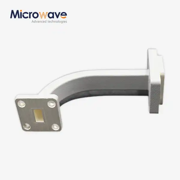
The H-plane tee in a microwave is a special waveguide joint where the side arm connects to the main guide along the wider wall, perpendicular to it. This line is aligned with the dominant TE10 mode's magnetic field vector. In circuit theory, this arrangement makes a parallel link, which means that when power comes in through the side arm, the collinear ports produce equal-magnitude, in-phase outputs. The shape keeps magnetic field lines from getting messed up as little as possible, which means that there is less insertion loss than with other types of junctions.
Physical Construction and Operational Principles
To make something, aluminum or copper metals are first carefully cut with a CNC machine to make the three-port junction with very tight limits on size. VSWR values below 1.20:1 are possible across all working bandwidths thanks to internal matching elements, which are usually inductive posts or irises. These elements make up for reactive discontinuities at the joint. This design is different from E-plane versions because the extra arm is on the narrow wall, which has a direct effect on how the impedance changes.
Frequency Range and Application Suitability
We make H-plane tees that work with waveguide bands from WR-2300 to WR-28 and cover frequencies from 0.332 GHz to 40 GHz. In aerospace and defense, where small footprints and high power handling are needed for phased arrays, X-band and Ku-band models are the most common. Because of its high impedance, the shunt junction works especially well in corporate feed networks that need precise phase coherence across many radiating elements.
Impedance Management in Waveguide Networks
If you match the impedance correctly at the junction, standing waves that slow down the system can't form. Our designs use computer-optimized matching structures that have been checked through full-wave electromagnetic simulation. This makes sure that there are minimal reflection coefficients across certain bandwidths. This focus on impedance control directly leads to more efficient antennas in satellite ground stations and more accurate measurements in calibration standards.
These fundamental characteristics position H-plane tees as essential building blocks in complex microwave architectures. When engineers choose parts for power distribution, they have to think about both the electrical factors and the mechanical integration needs so that the system works as well as it can.
Core Principles of Shunt Junction Impedance in H-Plane Tees
The electromagnetic boundary conditions at the three-port intersection cause the shunt junction impedance behavior. When the secondary arm connects to the main guide, it adds a side opening that needs to be fixed to keep the conditions equal. Because of the sudden change in structure, the joint has an inductive reactance that needs to be carefully tuned by making geometric changes or adding discrete matched elements. This control is vital for the H-plane tee in microwaves to function properly.
S-Parameter Characterization and Performance Metrics
Vector network analyzer measurements measure performance by looking at scattering parameters. In an ideal world, S13 and S23 should have the same magnitude and phase. In our production tests, we can see that the phase balance is within ±2 degrees and the amplitude imbalance is below ±0.25 dB for working bandwidths of ±10%. Insertion loss is usually less than 0.3 dB, and port isolation is more than 20 dB. This keeps collinear arms from coupling in a way that isn't wanted. These measurements show exactly how good the junction impedance is.
Material Selection and Field Distribution
For airborne uses, aluminum 6061 construction has great conductivity-to-weight ratios, while oxygen-free copper is used for high-power ground installs of H-plane tees in microwaves. At millimeter-wave frequencies, where current is mostly concentrated within micrometers of the surface, silver plating to a thickness of 3–5 µm lowers skin effect losses. By using HFSS simulation to look at the field distribution, you can find the best internal geometry. This makes sure that the impedance changes are the same across the junction.
Design Optimization for Impedance Matching
Through repeated modeling, the matching post width and penetration depth are changed to get rid of junction susceptance. Our engineering team uses special algorithms that find the best mix between VSWR minimization and bandwidth needs. This way, we can get broadband speed without making the hardware too complicated. The designs that were made have stable impedance characteristics across temperature ranges of -55°C to +85°C, which is very important for aerospace qualification.
Precise control of shunt junction impedance separates professional-grade components from lower-tier alternatives. When reviewing suppliers, purchasing teams should ask for full S-parameter data across all temperature and frequency ranges, as well as statistical process control paperwork that shows consistent manufacturing.
Comparative Insights: H-Plane Tee vs. Alternative Microwave Components
Microwave system architects choose between several junction types based on phase relationships and application constraints. The in-phase output of the H-plane tee in microwaves makes it different from E-plane setups, which have a 180-degree phase shift that works with different network topologies. Magic tees combine both planes, giving you four ports but making things bigger and more complicated.

Structural Differences and Phase Behavior
E-plane tees put the extra arm on the thin wall so it is parallel to the electric field. This creates series resistance properties. This makes outputs that are out of phase, which is good for monopulse comparators but not good for corporate feed applications that need coherent summation. H plane junctions naturally keep phase coherence, so beamforming assemblies don't need any extra phase correction networks.
Insertion Loss and Power Handling Comparisons
Our H-plane tees have about the same amount of insertion loss as E-plane variants: 0.15 dB at lower frequencies and 0.5 dB in millimeter-wave bands. Pulsed radar applications can handle up to several kilowatts of power, with breakdown voltage rather than heat loss being the main limit. Hybrid couplers offer similar isolation, but they usually lose 3 dB of power because of how they're designed to couple, which means that direct replacement isn't always the best option.
Application-Specific Component Selection
The small size of H-plane tees and the ability to split phases in subarrays serving 64 or 128 elements make phased array antennas for 5G base stations more useful. Even though it's more complicated, radar monopulse tracking needs magic tees because both sum and difference patterns need to be used at the same time. Earth stations that use satellite communication use H-plane junctions in redundant switching networks. In these networks, low insertion loss directly improves link budgets in Ka-band uplinks that are operating close to their maximum EIRP limits.
Material choices further differentiate applications—chromate conversion finishes work well in labs that aren't too harsh, while gold plating keeps naval radar from rusting in salt fog. When procurement specialists understand these trade-offs, they can match the specifications of a component to the needs of the operation without specifying too many expensive features.
Procurement Guide: How to Source the Best H-Plane Tee for Your Microwave Systems?
To find high-reliability waveguide components for your H-plane tee in microwave needs, you have to do more than just compare prices. You have to carefully evaluate each seller. Impedance matching is directly affected by how accurately the dimensions are measured, and long-term stability in hard settings is affected by the quality of the surface finish. Setting up clear specifications and validation protocols can help keep expensive integration failures from happening.
Supplier Qualification and Technical Capabilities
Reputable H-plane tee companies keep their ISO 9001:2008 approval and show that they follow RoHS rules, which shows that they have a method for managing quality. Our facilities have high-tech CMM inspection tools that check the internal waveguide measurements to within 0.025 mm. This stops the flanges from being out of alignment, which leads to RF leakage. Ask for proof that the vector network analyzer can be calibrated according to national standards. This will make sure that the measurements are correct during the incoming inspection.
Specification Review and Performance Validation
Frequency range, VSWR across working bandwidth, insertion loss, phase balance, and power handling capacity are some of the most important parameters. The datasheets should show the normal and highest values along with clear test conditions like the room temperature, the amount of power being applied, and the measurement reference lines. We provide full S-parameter Touchstone files that allow system-level simulation before the prototype is made, which cuts down on the number of design iterations.
Customization Capabilities and Lead Times
Many uses can be met by standard catalog items, but aerospace and defense projects often need custom frequency bands, non-standard flanges, or coatings that aren't available anywhere else. During the design process, our engineering team works together and provides 3D CAD models and electromagnetic simulation results to make sure the connection works before investing in tooling. Rapid development services can deliver the first units within three weeks, and production can grow to thousands of units while controlled processes keep the stability between units within ±0.1 dB.
After-Sales Support and Documentation
Each shipment comes with a full test report that shows how well the product worked compared to certain limits. Technical support experts help with installation and fixing. They fix impedance problems that are caused by interactions at the system level instead of problems with individual parts. Material and workmanship problems should be covered by the warranty, and there should be clear RMA methods to keep critical systems running as smoothly as possible.
Successful procurement balances technical needs with delivery dates and budget limits. Getting suppliers involved early in the design process lets you use their production knowledge, which can often help you find ways to cut costs by using standard setups that don't hurt performance.
Best Practices for Integrating H-Plane Tees into Microwave Networks
When installed correctly, the factory-optimized impedance qualities of the H-plane tee in microwaves are kept. However, when installed incorrectly, echoes are introduced that lower system performance. When putting something together and while it's working, it's important to pay close attention to things like mechanical alignment, torque specifications, and environmental sealing.
Mechanical Installation and Flange Interface Quality
To stop leaking and passive intermodulation, waveguide flanges need surfaces that are flat within 0.025 mm and have a finish better than 1.6 µm Ra. Before putting the parts together, clean the mating surfaces with isopropyl alcohol to get rid of any dust or dirt that could cause microscopic gaps. To make sure the gasket is compressed evenly without deforming the metal, torque the flange bolts in a star pattern to the manufacturer's recommended values, which are usually between 5 and 8 Nm for UG-series flanges.
Environmental Considerations and Pressurization
For outdoor installs, you need weatherproof shelters or pressurized waveguide systems to keep wetness out, which causes corrosion and more insertion loss. When our H plane tees are equipped with pressure windows, they can handle 15 PSI of internal pressure. This means they can support dehydrated nitrogen or dry air purge systems that are popular in tropical operations. Differential thermal expansion can loosen connections over thousands of cycles, which is why cycling the temperature from -40°C to +70°C is used to prove mechanical stability.
System-Level Performance Verification
Swept-frequency measurements taken after installation confirm the expected VSWR and insertion loss across all operational bands. Deviations mean that something isn't lined up right, there is contamination, or parts are broken and need to be fixed right away. In phased arrays, far-field pattern readings make sure that the phase is coherent across the feed network. Beam-pointing mistakes are usually caused by a single failed junction in corporate feeds that have dozens of H-plane tees.
Future Trends in Waveguide Junction Technology
Additive manufacturing promises complex internal geometries that can't be made with traditional machining. This could increase bandwidth and decrease size. We are looking into 3D-printed titanium alloys for uses in space that need to be stable at very high temperatures and have very little mass. Millimeter-wave 5G systems push H-plane tee designs toward 110 GHz, which requires tight tolerances for machining and high-tech surface treatments to keep conductor losses to less than 1 dB/meter in WR-10 guides.
These integration techniques set professional installations apart from those done by amateurs. For accurate post-installation validation, procurement teams should make sure that system integrators have the right assembly training and test equipment that has been properly calibrated.
Conclusion
In difficult microwave systems, mastering the shunt junction resistance characteristics is what separates good H-plane tee microwave performance from great results. The parallel admittance at the three-port joint needs to be precisely balanced using matched elements and dimensional control. This directly affects the VSWR, insertion loss, and phase balance. Choosing the right material from aluminum, copper, and different plating choices is important for balancing conductivity, weight, and weather resistance in a wide range of uses, from Earth stations in space to radar in the air. When you compare these to E-plane tees and magic tees, you can see which ones are better for your application. Best practices for buying make sure that the seller can meet your needs and that the specifications are followed. Using the right installation methods will keep the factory working well for a long time, which is important for mission-critical systems like communications and sensors that can't have their signals hacked.
FAQ
1. What distinguishes H-plane tees from E-plane configurations in practical applications?
The main difference is in the output phase relationships. H-plane tees send in-phase signals at ports that are parallel to each other, which is necessary for corporate feed networks in phased arrays where coherent power summation is needed. E-plane tees create 180-degree phase opposition, which is useful for differential and monopulse comparators. The way an impedance transforms depends on the orientation of the junction with respect to the field vectors. This affects the matching network complexity and the bandwidth that can be used while still staying within acceptable VSWR limits.
2. How does shunt junction impedance affect overall system performance?
When joint impedance matching isn't done right, standing waves are created. These waves lower the efficiency of power transfer and make reflections worse, which can damage receivers. Discontinuities in impedance make noise figure and dynamic range worse in receive systems. Precision impedance control keeps the signal strong even when it goes through feed networks with many junctions. This is important because cumulative reflections can cause destructive interference that ruins the desired radiation pattern in phased arrays or adds ripple to measurement systems that need a flat frequency response.
3. Which suppliers provide the most reliable H-plane tee components for X-band radar systems?
Advanced Microwave Technologies Co., Ltd. makes X-band H-plane tees that meet strict military and aircraft standards and have been shown to work in temperatures ranging from -55°C to +85°C. Our ISO 9001:2008 certification and RoHS compliance make sure that the quality is always the same, and our custom OEM capabilities let us support different frequency bands and flange configurations. With more than twenty years of production experience and in-house testing up to 110 GHz, you can trust us in tough situations where a component failure is not an option.
Partner with a Trusted H Plane Tee Manufacturer for Superior Microwave Solutions
Advanced Microwave Technologies Co., Ltd. makes precision-engineered H-plane tees that work best in defence, aircraft, and satellite uses that need to control shunt junction impedance. We can make things from 0.332 GHz to 40 GHz with VSWR below 1.20:1. We have full documentation for the S-parameters and environmental qualification data. Our engineering team works with you from the first idea to mass production, whether you need catalogue parts or OEM designs that are specifically made for your own system architectures. Email craig@admicrowave.com to talk about your unique needs with skilled RF experts who know how important impedance matching is to mission success. As a top supplier of H plane tee in microwave, we promise quick prototypes, low prices for large orders, and technical support after the sale to ensure seamless integration into your microwave networks.
References
1. Collin, R.E. (2001). Foundations for Microwave Engineering, 2nd Edition. IEEE Press, New York.
2. Pozar, D.M. (2012). Microwave Engineering, 4th Edition. John Wiley & Sons, Hoboken, New Jersey.
3. Ragan, G.L. (1948). Microwave Transmission Circuits, MIT Radiation Laboratory Series Volume 9. McGraw-Hill, New York.
4. Marcuvitz, N. (1951). Waveguide Handbook, MIT Radiation Laboratory Series Volume 10. McGraw-Hill, New York.
5. Saad, T.S. (1971). "Waveguide Tee Junctions," IEEE Transactions on Microwave Theory and Techniques, Vol. 19, Issue 3, pp. 274-279.
6. Bhat, B. and Koul, S.K. (1987). Stripline-Like Transmission Lines for Microwave Integrated Circuits. Wiley Eastern Limited, New Delhi.