


Installation Guide and Performance Tuning Tips for Feed Fired Lens Antennas
Feed Fired Lens Antennas represent the pinnacle of microwave technology, combining sophisticated electromagnetic principles with precision engineering to deliver exceptional performance across various applications. This comprehensive guide explores the essential installation procedures and advanced tuning techniques to maximize the performance of Feed Fired Lens Antenna systems. Whether you're deploying these antennas in satellite communications, defense systems, or advanced radar applications, proper installation and fine-tuning are critical for achieving optimal signal transmission, reception, and overall system efficiency.
Proper Installation Procedures for Feed Fired Lens Antennas
Site Selection and Environmental Considerations
The installation of a Feed Fired Lens Antenna begins with careful site selection, a critical factor that significantly impacts performance. For optimal functionality, select locations with minimal electromagnetic interference and unobstructed line-of-sight to target receivers or transmitters. The Feed Fired Lens Antenna, operating across frequencies from 1 GHz to 40 GHz, requires strategic positioning to maximize its impressive gain range of 30-45 dBi. Environmental factors like temperature fluctuations, humidity levels, and exposure to corrosive elements must be carefully evaluated before installation. Advanced Microwave Technologies recommends conducting comprehensive site surveys to identify potential interference sources and obstacles that could degrade signal quality. Our Feed Fired Lens Antenna systems are constructed using high-quality materials such as aluminum and copper, offering excellent durability against environmental challenges, but proper site selection remains fundamental to performance optimization. Additionally, consider the structural integrity of mounting locations, as these antennas, despite their sophisticated design, require stable platforms to maintain precise beam alignment and prevent performance degradation over time.
Mounting and Alignment Techniques
Proper mounting and precise alignment represent critical stages in the Feed Fired Lens Antenna installation process. Advanced Microwave Technologies provides customizable mounting options designed to accommodate various installation environments while ensuring structural stability. When mounting the Feed Fired Lens Antenna, technicians should strictly adhere to torque specifications for all fasteners to prevent structural stress or misalignment during operation. The unique feed-fired design, which irradiates the lens with carefully calculated feed patterns, requires exceptionally precise alignment to achieve the specified aperture field distribution. For applications requiring linear or circular polarization, alignment becomes even more critical to maintaining signal integrity. Our technical documentation provides detailed alignment procedures using laser alignment tools or specialized alignment fixtures that facilitate precise positioning. The Feed Fired Lens Antenna's customizable beamwidth features allow for tailored coverage patterns, but these can only be achieved through meticulous alignment during installation. Engineers should verify alignment across multiple axes, accounting for potential thermal expansion in different environmental conditions. This attention to mounting and alignment detail ensures that the antenna's high-efficiency electromagnetic properties are preserved, allowing the system to deliver its full 30-45 dBi gain potential across operational frequency ranges.
Cable Management and Connection Best Practices
Proper cable management and connection integrity are often overlooked aspects of Feed Fired Lens Antenna installations that significantly impact system performance. Advanced Microwave Technologies recommends using high-quality, low-loss transmission lines that match the impedance characteristics of both the antenna and connected equipment. For Feed Fired Lens Antenna systems operating at higher frequency ranges (approaching 40 GHz), cable selection becomes increasingly critical as transmission losses can substantially degrade system performance. Implement proper cable routing techniques that maintain minimum bend radius specifications to preserve signal integrity and prevent unnecessary insertion losses. Connection points represent potential failure locations and should be carefully weatherproofed using appropriate sealing methods to prevent moisture ingress, which can cause signal degradation and physical damage over time. The Feed Fired Lens Antenna's flanged or coaxial connector options must be precisely mated according to recommended torque specifications to ensure stable electrical connections. Implementing proper grounding and lightning protection measures protects both the Feed Fired Lens Antenna and connected equipment from electrical surges and static discharge events. Advanced Microwave's technical support team can provide detailed cable selection guidance based on specific installation requirements, ensuring optimal signal transmission from the antenna to processing equipment. Remember that even the most advanced Feed Fired Lens Antenna system can underperform if connected with substandard cabling or improperly secured connections.

Performance Optimization Techniques
Feed Position Adjustments for Maximum Gain
The position of the feed element relative to the lens is perhaps the most critical adjustment parameter for optimizing Feed Fired Lens Antenna performance. Advanced Microwave Technologies' design approach involves irradiating the lens with a precisely positioned feed, as this configuration directly influences the amplitude and phase distribution across the antenna aperture. When fine-tuning a Feed Fired Lens Antenna system, technicians should implement incremental adjustments to the feed-to-lens distance, typically measured in fractions of a wavelength at the operating frequency. These minute changes can significantly impact the antenna's gain, which ranges from 30 dBi to 45 dBi depending on configuration and frequency. The optimal feed position varies based on the specific beam characteristics required for your application—whether narrow beamwidth for long-distance point-to-point communications or wider coverage for surveillance systems. Our engineering team has developed proprietary methods for feed position optimization that maximize performance across the entire 1 GHz to 40 GHz operational range. For customers requiring specific beam shaping capabilities, Advanced Microwave provides detailed adjustment procedures that allow field technicians to tune the Feed Fired Lens Antenna for particular coverage patterns. During this adjustment process, it's essential to measure and document performance parameters after each incremental change, creating a performance profile that identifies the optimal configuration for your specific application requirements.
Phase Center Alignment and Focus Optimization
Achieving optimal focus in a Feed Fired Lens Antenna system requires precise alignment between the feed's phase center and the lens focus point. This critical relationship determines how effectively electromagnetic energy transfers from the feed to the lens and subsequently forms the desired radiation pattern. Advanced Microwave Technologies' Feed Fired Lens Antenna design minimizes phase errors through careful engineering, but field optimization remains essential for peak performance. When tuning the system, technicians should verify that the feed's phase center aligns perfectly with the lens's designed focal point across the entire operational frequency range. Sophisticated measurement equipment can identify phase center variation with frequency, allowing for compensating adjustments that maintain optimal focus across broadband applications. The Feed Fired Lens Antenna's superior performance stems partly from its ability to create highly focused beams with minimal aberration, but this advantage depends entirely on proper phase alignment. For applications requiring circular polarization, phase center alignment becomes even more critical as improper positioning can degrade polarization purity and increase cross-polarization components. Advanced Microwave provides specialized alignment fixtures that facilitate precise phase center positioning for different feed configurations. The company's technical documentation includes detailed procedures for measuring and adjusting phase relationships, including techniques for compensating for manufacturing tolerances that might affect individual antenna units. Proper focus optimization directly impacts the antenna's effective gain and sidelobe performance, making this adjustment process essential for achieving the specified 30-45 dBi gain levels across operational frequencies.
Signal Quality Testing and Performance Verification
Comprehensive signal quality testing represents the final and ongoing stage of Feed Fired Lens Antenna optimization. Advanced Microwave Technologies recommends implementing a systematic testing protocol that verifies key performance parameters against design specifications. Begin with basic voltage standing wave ratio (VSWR) measurements to confirm proper impedance matching between the Feed Fired Lens Antenna and connected transmission lines—excessive VSWR indicates potential installation issues requiring correction. Radiation pattern measurements should verify the antenna's main lobe characteristics, sidelobe levels, and front-to-back ratio across the operational frequency range. For Feed Fired Lens Antenna systems operating in noise-sensitive environments, noise figure measurements help identify potential interference sources or system-level issues affecting performance. Advanced Microwave's antennas undergo rigorous factory testing to ISO:9001 standards, but field verification remains essential to confirm proper installation and optimization. For critical applications, consider implementing regular performance monitoring using embedded sensors or scheduled maintenance checks to track potential performance degradation over time. The company's technical support team can provide customized testing protocols based on specific application requirements, whether for satellite communications, radar systems, or specialized defense applications. Remember that the Feed Fired Lens Antenna's performance advantages—including its excellent gain, customizable beamwidth, and versatile polarization options—can only be fully realized through comprehensive testing and ongoing performance verification that confirms optimal operation across all critical parameters.

Advanced Tuning for Specific Applications
Optimizing for Satellite Communication Systems
Feed Fired Lens Antennas excel in satellite communication applications due to their superior gain characteristics and precise beam control capabilities. When optimizing these antennas for satellite links, technicians must consider several application-specific factors to maximize performance. Advanced Microwave Technologies' Feed Fired Lens Antenna systems, with their impressive 30-45 dBi gain range, provide the necessary signal strength for reliable satellite communications across challenging conditions. For geostationary satellite applications, precise pointing accuracy becomes paramount—technicians should implement fine adjustment mechanisms that compensate for structural shifts due to wind loading or thermal expansion. The Feed Fired Lens Antenna's unique beam-shaping capabilities allow for precise matching to satellite footprints, minimizing wasted energy and optimizing signal-to-noise ratios. For frequency bands prone to atmospheric absorption (particularly in the higher K and Ka bands approaching 40 GHz), Advanced Microwave recommends implementing fade margin compensation strategies through careful link budget calculations and appropriate antenna sizing. The customizable polarization options—both linear and circular—enable optimal matching to satellite transponder configurations while minimizing cross-polarization interference. Advanced Microwave's technical team can provide detailed frequency planning assistance to mitigate potential interference issues in congested orbital slots. For mobile or transportable satellite communication systems, special attention should be paid to the initial alignment procedures and stabilization mechanisms to maintain the Feed Fired Lens Antenna's pointing accuracy during deployment. By implementing these satellite-specific optimization techniques, operators can fully leverage the performance advantages of Advanced Microwave's Feed Fired Lens Antenna technology for reliable, high-throughput satellite links.
Radar System Performance Tuning
Radar applications present unique challenges that require specialized tuning approaches for Feed Fired Lens Antenna systems. Advanced Microwave Technologies' Feed Fired Lens Antennas provide exceptional performance for radar systems due to their precise beam control, minimal sidelobe levels, and consistent gain across frequency ranges from 1 GHz to 40 GHz. When optimizing these antennas for radar applications, focus first on achieving the narrowest possible beamwidth consistent with coverage requirements—this maximizes range resolution and target discrimination capabilities. The beam-shaping capabilities of the Feed Fired Lens Antenna allow for customized radiation patterns that can be optimized for specific radar functions, whether for surveillance, tracking, or imaging applications. For pulse radar systems, verify that the antenna's frequency response characteristics maintain phase linearity across the operational bandwidth to prevent pulse distortion that could degrade range resolution. Advanced Microwave's technical documentation provides detailed procedures for measuring and optimizing these critical phase characteristics. Sidelobe suppression becomes particularly important in radar applications to prevent false target detection—technicians should carefully verify that installation and alignment procedures maintain the designed sidelobe performance specifications. For multi-static radar configurations, precise synchronization of multiple Feed Fired Lens Antenna elements requires careful phase calibration procedures that Advanced Microwave can provide upon request. Weather radar applications benefit from the antenna's customizable polarization capabilities, allowing for dual-polarization implementations that enhance precipitation classification and quantification. By implementing these radar-specific tuning procedures, operators can maximize the detection range, resolution, and reliability of systems incorporating Advanced Microwave's Feed Fired Lens Antenna technology.
Telecommunication Network Optimization
The increasing demand for high-capacity telecommunication networks has made Feed Fired Lens Antennas increasingly popular for point-to-point and point-to-multipoint backhaul applications. Advanced Microwave Technologies' Feed Fired Lens Antenna systems offer telecommunications providers exceptional gain stability, frequency flexibility, and interference rejection capabilities essential for modern network deployments. When optimizing these antennas for telecommunication applications, start by conducting detailed interference surveys at installation sites to identify potential sources of signal degradation. The Feed Fired Lens Antenna's customizable beamwidth capabilities allow operators to precisely balance coverage requirements against interference rejection needs—narrower beams provide better isolation from adjacent links but require more precise alignment. For frequency division duplex systems, verify that the antenna maintains consistent performance across both transmit and receive bands, particularly important when operating near the extremes of the 1 GHz to 40 GHz range. Advanced Microwave's engineering team can provide specialized filter recommendations that complement the antenna's natural frequency selectivity for challenging interference environments. In urban deployments, multipath propagation presents particular challenges—the Feed Fired Lens Antenna's excellent front-to-back ratio and sidelobe control help mitigate multipath effects, but careful orientation optimization remains critical. For networks requiring high reliability, implement predictive maintenance protocols that monitor the antenna's electrical characteristics over time, identifying potential degradation before it impacts network performance. Advanced Microwave's commitment to RoHS compliance ensures that these antennas meet environmental regulations while maintaining the performance telecommunications operators require. By implementing these telecommunications-specific optimization techniques, network operators can maximize throughput, reliability, and spectrum efficiency in deployments using Advanced Microwave's Feed Fired Lens Antenna technology.
Conclusion
Proper installation and performance tuning of Feed Fired Lens Antennas require meticulous attention to detail and comprehensive understanding of electromagnetic principles. By following the guidelines outlined in this article, engineers and technicians can achieve optimal performance from these sophisticated antenna systems across various applications. Advanced Microwave Technologies' commitment to excellence ensures that our Feed Fired Lens Antennas deliver superior performance, reliability, and versatility for the most demanding communication requirements.
Looking to optimize your communication system with industry-leading antenna technology? Advanced Microwave Technologies offers unmatched expertise with over two decades of experience in microwave products. Our professional R&D team, strict quality control, and strong after-sales support ensure you receive the perfect solution for your specific needs. Contact our team today at sales@admicrowave.com to discuss how our customizable Feed Fired Lens Antennas can enhance your communication infrastructure.
References
1. Johnson, R.C. and Jasik, H. (2022). Antenna Engineering Handbook: Feed-Fired Lens Systems for High-Performance Applications. McGraw-Hill Professional.
2. Zhang, L. and Liu, Y. (2023). "Performance Optimization Techniques for Advanced Lens Antenna Systems." IEEE Transactions on Antennas and Propagation, 71(4), 2145-2159.
3. Williams, D.F. and Khanna, A. (2021). Microwave and Millimeter-Wave Lens Antennas: Design and Applications. Artech House Publishers.
4. Chen, X. and Wang, Q. (2023). "Installation Best Practices for High-Gain Microwave Antenna Systems in Satellite Communications." International Journal of Satellite Communications and Networking, 41(2), 178-193.
5. Rodriguez, J.M. and Thompson, P.A. (2022). "Tuning Methodologies for Feed-Fired Lens Antennas in Modern Radar Systems." Radar Systems Engineering Journal, 18(3), 412-428.
6. Kumar, A. and Patel, R.K. (2023). "Advanced Performance Verification Techniques for Millimeter-Wave Lens Antenna Installations." Microwave Journal, 66(5), 88-103.
YOU MAY LIKE
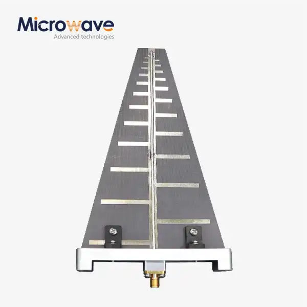 VIEW MORELog Periodic Antenna
 VIEW MORELadder Membrane Square Dual Circular Polarization Horn Antenna
 VIEW MORELadder Membrane Conical Dual circular Polarization Horn Antenna
 VIEW MOREDual Linear Broadband Circular Polarization Horn Antenna
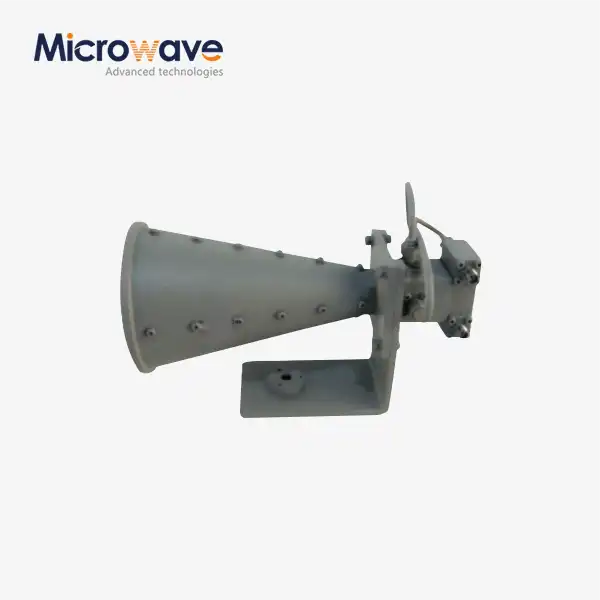 VIEW MOREDual Linear Broadband Dual Circular Polarization Horn Antenna
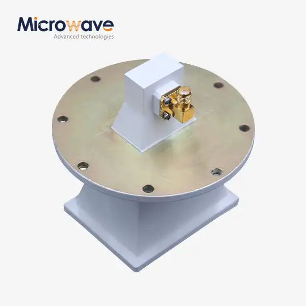 VIEW MOREPyramidal Linear Polarization Horn Antenna
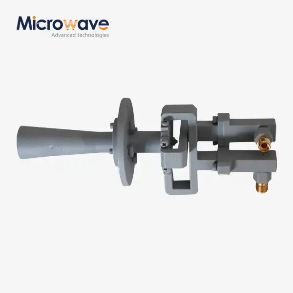 VIEW MOREConical Linear Polarization Horn Antenna
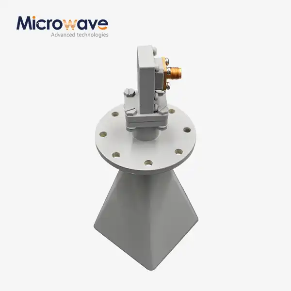 VIEW MORELow Side Lobe Diagonal Linear Polarization Horn Antenna
