Inside a Directional coupler & explanation of how they work
Have you ever struggled with signal monitoring in high-frequency systems where power measurements become unreliable, causing system failures or inaccurate data transmission? Understanding what's happening inside a Coaxial Directional Coupler and how these precision devices work is essential for engineers and technicians who need to maintain signal integrity across communication networks, radar installations, and satellite systems without disrupting the main signal path.
Understanding the Internal Structure of Coaxial Directional Couplers
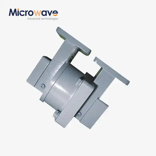
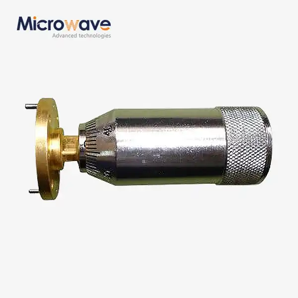
The internal architecture of a Coaxial Directional Coupler represents a sophisticated balance between electromagnetic theory and practical engineering. At its core, this device consists of two transmission lines positioned in close proximity, allowing controlled electromagnetic coupling between them. The primary transmission line carries the main signal from input to output, while a secondary coupled line samples a small, precise portion of this signal. The physical construction typically involves either a stripline or coaxial configuration, where the spacing between conductors, dielectric materials, and coupling apertures are meticulously calculated to achieve specific coupling coefficients. In modern Coaxial Directional Coupler designs, manufacturers employ precision machining and careful material selection to ensure consistent performance across wide frequency ranges. The coupling mechanism relies on the distributed electromagnetic field that exists around any current-carrying conductor. When high-frequency signals propagate through the main line, they generate electric and magnetic fields that extend beyond the conductor boundaries. By positioning a secondary line within this field at an optimal distance, a portion of the electromagnetic energy couples into the auxiliary port. The coupling strength depends on several factors including the length of the coupling region, the separation distance between lines, and the dielectric constant of the insulating material. Advanced designs incorporate multiple coupling sections to flatten the frequency response and achieve broadband performance from DC to 40 GHz and beyond, meeting the demanding requirements of modern communication systems.
The Physics Behind Directional Coupling
The fundamental operating principle of a Coaxial Directional Coupler stems from the interaction between forward and backward traveling electromagnetic waves. When a signal enters the input port, it propagates along the main transmission line while simultaneously inducing currents in the adjacent coupled line through both electric and magnetic field interactions. The directivity characteristic, which distinguishes these devices from simple power dividers, arises from the phase relationships between these induced signals. In an ideal Coaxial Directional Coupler, the coupled port responds only to forward-traveling waves, while the isolated port theoretically receives no power from the input signal. This directional selectivity occurs because the electromagnetic coupling happens over an extended physical length, typically a quarter-wavelength or more at the center operating frequency. During this distributed coupling process, signals coupled at different points along the transmission line arrive at the coupled port with constructive phase relationships, while they arrive at the isolated port with destructive interference. The quality of this directional performance depends heavily on manufacturing precision and the symmetry of the coupling structure. Modern Coaxial Directional Coupler technology achieves isolation values exceeding 30 dB, meaning that less than 0.1% of the input power appears at the isolated port, enabling accurate power monitoring and standing wave measurements in sophisticated RF and microwave systems deployed across telecommunications infrastructure and aerospace applications.

Key Internal Components and Materials
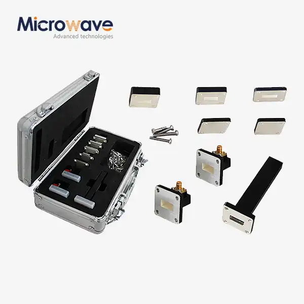
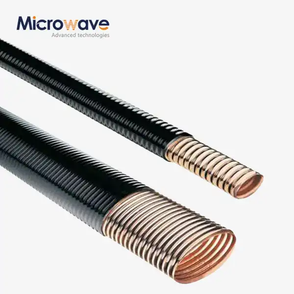
The performance characteristics of a Coaxial Directional Coupler are directly influenced by the materials and components used in its construction. The outer housing, typically fabricated from aluminum or stainless steel, provides electromagnetic shielding and mechanical stability. Aluminum offers excellent conductivity and is lightweight, making it ideal for aerospace applications where weight reduction is critical. Stainless steel, while heavier, provides superior corrosion resistance for harsh environmental conditions encountered in maritime and outdoor installations. The internal conductors, usually composed of high-purity copper or silver-plated copper, minimize resistive losses that would otherwise degrade insertion loss performance. The dielectric spacers separating the conductors represent another critical element, with materials like PTFE (Teflon) or low-loss ceramic compounds chosen for their stable dielectric constants across temperature variations and frequency ranges. These dielectric materials maintain consistent electrical properties from DC to 110 GHz, ensuring reliable performance in applications spanning legacy communication systems to cutting-edge 5G and emerging 6G networks. The connectors integrated into the Coaxial Directional Coupler design, whether SMA, N-Type, or custom configurations, must provide repeatable, low-VSWR connections while maintaining power handling capabilities up to 500 W for high-power radar and transmitter applications. Advanced manufacturing techniques including precision CNC machining, laser welding, and automated assembly ensure that dimensional tolerances remain within micrometers, which is essential for maintaining specified coupling values of 10 dB, 20 dB, or 30 dB across the operating bandwidth with insertion losses as low as 0.2 dB.
How Coaxial Directional Couplers Function in Real Systems?
The operational versatility of a Coaxial Directional Coupler makes it indispensable across numerous high-frequency applications. In practical deployment, these devices serve multiple critical functions including power monitoring, signal sampling, reflection measurement, and feedback control. When installed in a transmitter output path, the Coaxial Directional Coupler continuously samples a known fraction of the forward power without significantly affecting the main signal, allowing engineers to monitor transmission levels in real-time. Simultaneously, by observing the isolated port, any reflected power resulting from antenna mismatches or transmission line faults becomes immediately apparent. This dual monitoring capability proves essential in satellite ground stations where maintaining optimal power transfer to dish antennas ensures reliable communication links for HD video, data services, and voice communications across vast distances. The coupling mechanism operates passively, requiring no external power supply and introducing minimal insertion loss typically below 0.2 dB, which preserves signal strength in power-sensitive applications. The frequency response characteristics of modern Coaxial Directional Coupler designs achieve flat coupling values across ultra-wide bandwidths, supporting systems that operate across multiple frequency bands simultaneously. This broadband capability becomes increasingly important as communication systems evolve to utilize spectrum more efficiently, with cellular base stations, military radars, and aerospace navigation systems requiring components that perform consistently from hundreds of megahertz to tens of gigahertz without adjustment or tuning.
Signal Flow and Port Configuration
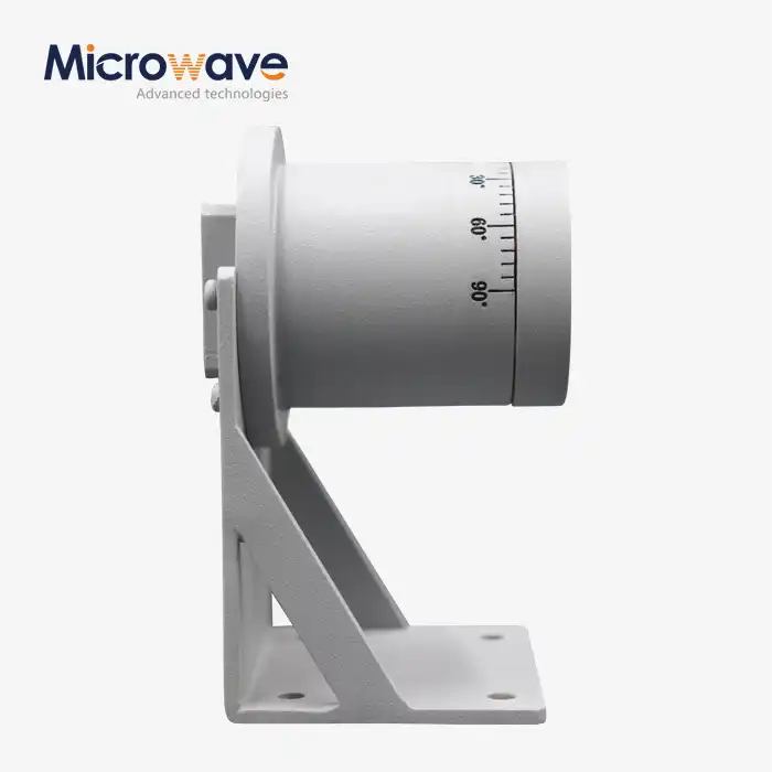
A standard Coaxial Directional Coupler features four ports, each serving a distinct function in the signal routing architecture. The input port receives the primary signal from sources such as transmitters, amplifiers, or signal generators. This signal propagates through the main line to the output port with minimal attenuation, typically experiencing insertion losses of 0.2 dB or less in high-quality designs. The coupled port provides a precise, attenuated sample of the forward-traveling signal, with the coupling coefficient determining the exact attenuation value. Common coupling values include 10 dB, 20 dB, and 30 dB, meaning the coupled signal is 10, 100, or 1000 times weaker than the main signal respectively. This predictable attenuation allows engineers to use lower-power measurement equipment and prevents damage to sensitive spectrum analyzers or power meters. The isolated port, positioned opposite the coupled port, theoretically receives no power from forward-traveling signals but responds to any reflected energy returning from the load. This port enables standing wave ratio measurements and reflection coefficient analysis, critical parameters for optimizing antenna systems and detecting transmission line faults. The isolation between the input port and isolated port, typically exceeding 30 dB in quality Coaxial Directional Coupler designs, ensures accurate measurements even when reflected power levels are much lower than forward power. This four-port architecture, combined with the passive nature of the coupling mechanism, allows engineers to insert the device into existing systems with minimal disruption, making it an essential tool for system commissioning, maintenance, and troubleshooting across telecommunications networks, radar installations, and aerospace communication systems.
Temperature Stability and Environmental Performance
The reliability of a Coaxial Directional Coupler under varying environmental conditions directly impacts system uptime and measurement accuracy. Temperature fluctuations affect both the physical dimensions of the device and the electrical properties of its materials, potentially causing shifts in coupling coefficients and degrading directivity performance. Advanced designs address these challenges through careful material selection and thermal compensation techniques. The coefficient of thermal expansion for the housing material must be matched to that of the internal conductors to prevent mechanical stress and maintain precise conductor spacing as temperatures vary from -40°C to +85°C or beyond. Dielectric materials exhibit temperature-dependent permittivity changes that can shift the electrical length of coupling sections, altering frequency response characteristics. High-quality PTFE and ceramic dielectrics minimize these variations, ensuring that a Coaxial Directional Coupler calibrated at room temperature maintains its specified performance across the full operating temperature range. In harsh environments such as mountaintop communication sites, offshore platforms, and aerospace applications, moisture ingress represents another significant threat. Hermetic sealing techniques, gasket interfaces, and conformal coatings protect internal components from humidity, salt spray, and condensation that could otherwise cause corrosion and electrical failures. The robust construction methodology employed by leading manufacturers results in products capable of withstanding extreme temperatures, moisture exposure, vibration, and shock loading while continuously delivering accurate signal sampling with VSWR values of 1.2:1 or better. This environmental resilience, combined with the inherent reliability of passive components, enables Coaxial Directional Coupler installations to operate for decades with minimal maintenance, providing excellent long-term value in mission-critical applications where system downtime translates directly to lost revenue or compromised safety.
Practical Applications and System Integration
The Coaxial Directional Coupler serves as a fundamental building block in countless RF and microwave systems across diverse industries. In telecommunications infrastructure, these devices enable continuous monitoring of transmitter output power at cellular base stations, allowing network operators to verify compliance with regulatory power limits while detecting amplifier degradation or antenna system faults before they impact service quality. The coupled port signal feeds into automated monitoring systems that can alert maintenance teams to developing problems, enabling proactive repairs that minimize customer impact. Radar systems rely heavily on Coaxial Directional Coupler technology for both transmit power monitoring and receiver protection, with the isolated port detecting antenna mismatches that could cause damaging reflections to high-power transmitter stages. Military surveillance radars operating in hostile environments benefit from the robust construction and reliable performance that prevents mission-critical failures during extended deployments. Satellite communication ground stations employ precision Coaxial Directional Coupler units to sample both uplink and downlink signals, facilitating link budget calculations and ensuring optimal power distribution for reliable data transmission to and from orbiting spacecraft. The aerospace industry integrates these devices into aircraft navigation systems, communication transceivers, and collision avoidance radars where weight constraints demand compact designs without performance compromises. Research and development laboratories utilize Coaxial Directional Coupler technology extensively for component characterization, antenna testing, and system debugging, with the ability to simultaneously monitor forward and reflected power accelerating development cycles and improving product quality. The versatility of these passive devices, combined with their ability to operate across frequency ranges from DC to 110 GHz with coupling accuracies better than ±0.5 dB, makes them irreplaceable tools for modern RF and microwave engineering.
Measurement and Testing Capabilities
When integrated into test and measurement setups, a Coaxial Directional Coupler transforms into a powerful diagnostic tool that reveals system performance characteristics invisible through simple power measurements. By connecting the coupled port to a spectrum analyzer, engineers can observe the detailed frequency content of transmitted signals without disrupting the main signal path to the antenna or load. This non-intrusive monitoring capability proves essential when characterizing transmitter spurious emissions, intermodulation products, or spectral mask compliance for regulatory certification. The isolated port simultaneously provides critical information about load matching and transmission line integrity. When a Coaxial Directional Coupler is installed near an antenna feed point, the ratio between forward and reflected power directly indicates the voltage standing wave ratio, a key metric for antenna system performance. A well-matched antenna system with VSWR below 1.5:1 indicates efficient power transfer, while elevated VSWR values signal potential problems such as damaged cables, loose connectors, or detuned antenna elements. In production testing environments, automated test equipment incorporates Coaxial Directional Coupler assemblies to enable high-throughput device characterization with minimal test port connections. The stable, repeatable performance of quality couplers ensures measurement accuracy across thousands of test cycles, supporting statistical process control and quality assurance programs. Advanced measurement scenarios combine multiple Coaxial Directional Coupler units to create sophisticated test configurations such as loop-back paths for two-port device characterization or multi-path signal distribution for phased array antenna testing. The low insertion loss characteristic, typically 0.2 dB, minimizes measurement uncertainty and allows accurate characterization of low-gain devices without introducing excessive noise figure degradation.

Selecting the Right Coaxial Directional Coupler for Your Application
Choosing an appropriate Coaxial Directional Coupler requires careful consideration of multiple performance parameters and application-specific requirements. The frequency range represents the primary selection criterion, with the device bandwidth needing to encompass all operating frequencies with adequate margin. For applications requiring coverage from sub-gigahertz frequencies through microwave bands, ultra-broadband designs extending from DC to 40 GHz or even 110 GHz provide maximum flexibility for multi-band systems and future upgrades. The coupling value must be selected based on the desired sample strength and the input power levels present in the system. For high-power transmitter monitoring where input signals may reach hundreds of watts, a 30 dB coupler provides adequate attenuation to protect measurement equipment while still delivering sufficient coupled power for accurate readings. Conversely, low-power receiver applications might employ 10 dB couplers to maximize the sampled signal strength. Power handling capability becomes critical in transmitter applications, with continuous power ratings up to 500 W or more required for broadcast and radar systems. The physical form factor and connector type must match the installation environment and existing system interfaces, with options including SMA connectors for laboratory equipment, N-Type connectors for high-power outdoor installations, or custom configurations for specialized integration requirements. Directivity and isolation specifications determine measurement accuracy, with values exceeding 30 dB ensuring that reflected power measurements remain uncontaminated by forward power leakage. Environmental specifications including temperature range, humidity resistance, and vibration tolerance should align with the deployment scenario, whether that involves temperature-controlled equipment rooms, outdoor mountaintop installations, or aerospace platforms experiencing extreme conditions. Working with experienced manufacturers like Advanced Microwave Technologies Co., Ltd ensures access to both standard product lines and custom OEM solutions tailored to specific application requirements.
Conclusion
Understanding the internal structure and operational principles of Coaxial Directional Coupler technology empowers engineers to design more reliable, efficient RF and microwave systems across telecommunications, radar, aerospace, and satellite communication applications, while proper selection and integration ensures optimal performance and measurement accuracy.
Cooperate with Advanced Microwave Technologies Co., Ltd.
Advanced Microwave Technologies Co., Ltd. stands ready to support your project requirements with over 20 years of specialized expertise in RF and microwave component manufacturing. Our comprehensive product portfolio includes precision Coaxial Directional Coupler solutions spanning DC to 110 GHz, backed by ISO 9001:2008 certification and RoHS compliance for environmental sustainability. As a leading China Coaxial Directional Coupler manufacturer, China Coaxial Directional Coupler supplier, and China Coaxial Directional Coupler factory, we deliver High Quality Coaxial Directional Coupler products with competitive Coaxial Directional Coupler price points and China Coaxial Directional Coupler wholesale options. Our state-of-the-art 24m Microwave Darkroom enables precise antenna and component characterization from 0.5 to 110 GHz, ensuring every product meets stringent performance specifications. We offer complete OEM services including custom frequency ranges, coupling values, connector types, and mechanical configurations tailored to your exact requirements, supported by rapid prototyping and expert technical assistance. Whether you need Coaxial Directional Coupler for sale in standard configurations or require application-specific designs for satellite communications, defense systems, aerospace projects, or telecommunications infrastructure, our engineering team provides comprehensive support from initial concept through production delivery. Contact our team today at craig@admicrowave.com to discuss your specific requirements and discover how our technical expertise, advanced manufacturing capabilities, and commitment to quality can accelerate your project success. Save this resource for future reference when component selection challenges arise.
References
1. "Microwave Engineering" by David M. Pozar - Comprehensive technical reference covering directional coupler theory, design equations, and practical implementation considerations for RF and microwave systems.
2. "RF and Microwave Coupled-Line Circuits" by Rajesh Mongia, Inder Bahl, and Prakash Bhartia - Detailed analysis of coupled transmission line structures, coupling mechanisms, and broadband directional coupler design techniques.
3. "The Design of Directional Couplers" by Julius Lange, Microwave Journal - Classic technical paper presenting fundamental coupling theory and mathematical models for predicting coupler performance characteristics.
4. "Handbook of Microwave Component Measurements" by Joel P. Dunsmore - Practical guide to testing and characterizing directional couplers including measurement procedures, calibration techniques, and accuracy optimization methods.