


How Waveguide Isolator Improves System Stability in Workshop
Waveguide Isolators are very important safety parts in RF and microwave workshops because they allow signals to go only one way while collecting reflected energy that would otherwise make source equipment unstable. These non-reciprocal devices greatly lower frequency drift, keep signal distortion to a minimum, and extend the useful life of expensive test equipment by stopping harmful back-reflections from reaching sensitive amplifiers and oscillators. When Waveguide Isolators are built into calibration stations, antenna measurement systems, and prototype assembly lines, they create stable electromagnetic conditions that make measurements more accurate and cut down on expensive equipment failures.
Understanding Waveguide Isolators and Their Role in System Stability
We at Advanced Microwave Technologies Co., Ltd. have seen how Waveguide Isolators change the stability of a workshop because of the way they work with electromagnetic fields. To control the direction of signals, these passive ferrite devices use Faraday rotation principles in waveguide structures that have been carefully designed. The ferrite material works with fixed magnets that are placed in a certain way to change the polarization plane of electromagnetic waves. This stops signals from going back to the source and sends them instead to internally matched termination loads.
Operating Principles and Core Functionality
The basic function depends on the fact that magnetized ferrite materials don't magnetize backwards or forwards. Forward signals barely lose any power as they go through the Waveguide Isolator—about 0.3 to 0.8 dB insertion loss, based on the frequency and design. Reverse sounds are isolated by 20 to 30 dB or more, which protects upstream components. This ability to choose the way of the signal is very useful in workshops where reflections can be caused by uneven loads, open connections during testing, or mistakes made by the operator.
Workshop Application Contexts
Putting a Waveguide Isolator between signal sources and the devices being tested is very helpful for testing labs. Waveguide Isolators keep changes in the test item's impedance from pulling the source frequency or ruining expensive synthesizers while antenna far-field measurements are being done in our 24m microwave lab. These devices are used on assembly lines for satellite communication systems to keep local oscillators stable during module integration. At calibration stations, they keep the purity of the reference signal during test runs that last for hours.
Technical Performance Parameters
When purchasing, experts look at these parts; they should pay attention to several specs. Coverage frequencies need to match the working bands. For WR-28 uses, our wide-band designs cover the whole waveguide range, from 26.5 to 40 GHz. Power handling ability is split into two parts: peak power (which is limited by voltage breakdown and is usually several kilowatts for pulsed radar uses) and average power (which is limited by thermal loss and is usually 10 to 500 watts). Specifications for VSWR below 1.25:1 make sure that precise measurement chains have little signal disturbance.

Key Challenges in Workshop System Stability and How Waveguide Isolators Solve Them
There are a lot of threats to stability in industrial microwave settings that hurt both production and the accuracy of measurements. Reflected power is the most harmful factor. It happens when impedance breaks happen at connections, cable bends, or equipment that is only partly put together, sending energy back toward signal sources. Moving wave tubes suffer frequency pulling, solid-state amplifiers gain compression, and oscillators phase noise decline because of this reverse energy.
Mitigating Reflection-Induced Instabilities
Waveguide Isolators that are properly designed can deal with these problems by systematically absorbing reflected energy. The internal terminal load turns electromagnetic energy that is moving backwards into heat. This heat is then spread out through the device housing. When we tested satellite transponder modules, adding Waveguide Isolators cut frequency variation from ±150 kHz to ±20 kHz when the load changed. This directly improved signal quality standards. The isolation function makes a stable impedance setting so that source equipment can work as planned, even if things change downstream.
Thermal Management in Demanding Environments
Isolator termination loads get very hot when they are used in high-power workshop applications. Our engineers have come up with a way to solve this problem using advanced thermal design and aluminum housings with fin shapes that are designed for natural convection cooling. If the average power is more than 200 watts, the terminations may need to be cooled by forced air or water. Temperature-compensated magnet systems keep their separation performance from -40°C to +85°C, which is very important for testing aircraft parts in conditions that are similar to those found at high altitudes.
Documented Performance Improvements
A defense contractor that makes phased array radar modules said that adding broadband Waveguide Isolators to their test stations cut the time it took to calibrate them by 40%. Because the source conditions were stable, there was no need to re-reference often, and multiple channels could be tested at the same time without cross-coupling disturbance. In the same way, a satellite ground station user saw their high-power amplifier chains last longer between failures—from 18 months to over 60 months—after adding Waveguide Isolators at key contact points.
Comparing Waveguide Isolators with Alternative Solutions
Knowing what other companies are selling RF safety parts helps buying teams make smart choices that meet the needs of the workshop. Waveguide Isolators have unique performance characteristics that set them apart from other technologies. These include the ability to handle high power, low insertion loss, and a wide bandwidth.
Circulators Versus Isolators
Three-port circulators send signals from one port to another in a certain order. This makes them flexible for uses that need to watch signals or set up two paths at the same time. But circulators need terminations on the outside and have a higher insertion loss (usually 0.5 to 1.2 dB) than two-port Waveguide Isolators. Dedicated Waveguide Isolators work best in workshop settings that want to protect sources simply and keep signal loss to a minimum. On the other hand, circulator implementations work best in test systems that need to connect in both directions.
Coaxial Versus Waveguide Technologies
Although coaxial isolators come in small packages and have easy-to-use connections, they have power limits and more passive intermodulation. Waveguide setups work best in situations above 18 GHz, where the amount of power needed is higher than what cable can handle. Based on our tests, Waveguide Isolator designs can handle up to 500 watts of power on average in X-band uses, while coaxial units can only handle 50 watts at most. The wider waveguide cross-section also lowers voltage differences, which lowers the risk of multipaction in high-altitude aircraft uses.
Attenuators and Directional Couplers
Fixed attenuators lower signal levels in both directions but don't separate them, so they can't be used to protect the source. They work together to level the power, but they can't stop reflections. Directional couplers take samples of forward and backward power for monitoring reasons, but they don't take in reflected energy. For the workshop to be stable, these parts often need to be combined with Waveguide Isolators. The coupler lets you see what's wrong, and the Waveguide Isolator protects the equipment.
When it comes to precision workshops, Waveguide Isolators are the only ones that can handle high isolation, low insertion loss, and multiple hundred-watt power across full waveguide bands. This performance trinity makes single-component solutions possible when other methods would need complicated multi-element systems with dependability and performance drops over time.
Procurement Guide: Selecting and Buying the Right Waveguide Isolator for Your Workshop
To choose the right isolation components, you need to carefully weigh the technical needs against the supplier's skills and the cost. Buyers should go through an organized process of figuring out what performance they need, making sure the quality is good, and judging the relationship.
Critical Selection Parameters
The frequency range is the most important parameter because it matches the device's coverage to the operating bands. Broadband units that cover the whole waveguide range (40%) work well in workshops that use a lot of different tools, while narrowband designs that are designed for specific center frequencies work better in test stations that only use those frequencies. When figuring out thermal loads for pulsed radar tests, pulse width and duty cycle must be taken into account along with average power loss and peak power transients. Specifications for VSWR below 1.20:1 are necessary for measurement systems that need to be very accurate with return loss.
Quality Verification and Certifications
Getting ISO 9001:2015 approval shows that a provider is dedicated to using uniform quality management systems and production methods. At ADM, our quality system goes beyond just basic approval. Before each Waveguide Isolator is shipped, it is put through a series of tests that check its entry loss, isolation, and power handling. RoHS compliance makes sure that people are responsible for the environment and meets the rules for defense and aircraft uses. Instead of depending only on the usual numbers on the datasheet, buyers should ask for test data paperwork that shows the actual measured performance.
Supplier Evaluation Criteria
Reliable makers show they know a lot about technology by being able to provide engineering help. Look for providers that offer electromagnetic modeling, unique frequency band optimization, and thermal analysis that is tailored to your needs. Manufacturing knowledge is very important. After 20 years of making microwave parts, we know how they fail and how to improve the design in ways that younger companies don't. Lead times are affected by production capacity. For example, well-known makers keep stock of parts for normal waveguide bands, but it takes 6 to 12 weeks for custom specifications.

Ordering Process and Commercial Considerations
The first step in the engagement process should be a technical consultation where experts talk about the unique needs of the application, the surroundings, and the limitations of the integration. ADM can make prototypes quickly—usually in three to four weeks for trial units that are tested for performance in our 110 GHz measurement lab. Prices vary a lot depending on frequency band, power rating, and bandwidth. Standard catalog items cost between $800 and $3,500, while special high-power versions cost between $4,000 and $15,000. Defense companies and telecommunications system designers that need to combine multiple units for production can save money by using volume procurement programs.
Support after the sale is what sets top sellers apart from commodity vendors. Full technical paperwork, startup instructions, and help with fixing problems make sure that deployment goes smoothly. Our field application experts help with starting complicated measurement systems on-site, and they can also answer common integration questions over the phone.
Future Trends and Technological Advances in Waveguide Isolators that Enhance Workshop Stability
Through breakthroughs in materials science and design optimization methods, innovation keeps improving the performance of Waveguide Isolators. Newer designs try to make things smaller and lighter while also making them better at managing heat and making their operating bandwidths bigger.
Material and Design Innovations
New ferrite mixtures created at the molecular level are more stable at higher temperatures and have less insertion loss. With the help of additive manufacturing, complex internal shapes can now be made that improve the spread of magnetic fields. This cuts down on stray fields that can damage sensitive electronics nearby. Full waveguide band coverage can be achieved in housings 30% smaller than standard designs when dielectric loading is used. This is useful for rack-mounted test systems that are limited in space.
Integration with Smart Workshop Systems
Demand for Waveguide Isolators with built-in temperature monitors and RFID tags that work with automated test equipment control systems is being driven by Industry 4.0 projects. Predictive maintenance programs look at trends in temperature performance to plan replacements before they break. Our engineering plan includes designs for Waveguide Isolators that are connected to the Internet of Things (IoT) and send real-time operating state reports to centralized facility management platforms. This lets the controls for the workshop setting be optimized based on data.
Long-Term Value Proposition
Buying high-quality Waveguide Isolators from well-known companies gives you measurable returns in a number of ways. Protecting equipment keeps amplifiers from breaking down in terrible ways that cost between $25,000 and $150,000 to fix or replace with solid-state power amplifiers or traveling wave tubes. As measurement accuracy goes up, test gaps go down. This lets specifications be followed more closely, which raises product output. Protecting test equipment properly can make it last longer, often doubling the average time between failures. This has big benefits for the total cost of ownership that outweigh the higher initial purchase price.
Broadband designs use less energy because they have less insertion loss than older narrowband units that need to be replaced often across a range of test frequencies. Environmental compliance through RoHS-compliant materials makes disposal easier and supports business sustainability efforts, which are becoming more and more important to buying partners.
Conclusion
Waveguide Isolators are essential parts for keeping systems stable in workshop settings that deal with high-frequency RF and microwave signals. How well they keep signals pure while protecting sensitive equipment from mirrored power has a direct effect on how accurate measurements are, how long equipment lasts, and how efficiently operations run. As microwave technology moves toward higher frequencies and higher power levels, it becomes more and more important that the separation parts are properly designed. Companies that care about precision and dependability in their testing and assembly see Waveguide Isolators as strategic investments rather than common parts. They choose suppliers who can show they are good at manufacturing, have technical knowledge, and offer full support.
FAQ
Q1: What causes waveguide isolators to fail in workshop environments?
The most common way for something to fail is for the internal terminal load to become too hot during long periods of high reflection. During testing, if any of the output ports experience short circuits or open conditions, all forward power is reflected and taken in by the Waveguide Isolator's load resistor. When the maximum average power is exceeded, the load material gets too hot, cracks, and the isolation performance is forever lost. For proper application, you need to make sure that the mirrored power stays within the device's limits, even when there is a fault.
Q2: How does temperature affect isolation performance?
The magnetic properties of ferrite change with temperature, which means that the best frequency for operation changes as the environment does. Waveguide Isolators of good quality have temperature-compensated magnet systems that keep specs the same from -40°C to +85°C. When compared to performance at room temperature, isolation usually drops by 2 to 4 dB at high and low temperatures. For use in places where temperature control is difficult, forced air cooling or temperature-controlled containers are helpful.
Q3: Can broadband isolators match narrowband performance?
When compared to narrowband units that are designed for specific center frequencies, broadband designs that cover full waveguide bands (about 40% fractional bandwidth) have to make technical trade-offs. Broadband Waveguide Isolators usually offer 20 to 25 dB of isolation with 0.5 to 0.8 dB of insertion loss, while narrowband Waveguide Isolators get 30 to 35 dB of isolation with 0.3 dB of insertion loss. Broadband flexibility is good for workshop settings that use more than one test frequency, while specific single-frequency uses may be able to explain the better performance of narrowband.
Partner with ADM for Superior Waveguide Isolator Solutions
For over twenty years, Advanced Microwave Technologies Co., Ltd has been making microwave components and is ready to help you with your workshop stability problems with precision-engineered Waveguide Isolator solutions. Our wide range of products includes standard waveguide bands from 0.5 GHz to 110 GHz, as well as special designs made to fit the needs of each application. As a well-known company that makes Waveguide Isolators, we use advanced measuring tools in our 24m microwave lab and follow manufacturing methods that are ISO 9001:2015 approved. Our engineering team can help you choose the best parts for any job, whether you need high-power designs for satellite communication systems or internet coverage for test stations that can be used for multiple tasks. You can talk about your technical needs with craig@admicrowave.com, and you'll get the same quality, speed, and technical depth that defense contractors, aerospace system designers, and telecommunications leaders depend on for mission-critical microwave components.
References
1. Helszajn, J. (2001). The Stripline Circulator: Theory and Practice. IEEE Press Series on Electromagnetic Wave Theory. Hoboken: Wiley-IEEE Press.
2. Baden Fuller, A.J. (1987). Ferrites at Microwave Frequencies. IEE Electromagnetic Waves Series 23. London: Peter Peregrinus Ltd.
3. Linkhart, D.K. (2008). Microwave Circulator Design (2nd ed.). Norwood: Artech House.
4. Pozar, D.M. (2011). Microwave Engineering (4th ed.). Chapter 9: Microwave Filters. Hoboken: John Wiley & Sons.
5. Ishii, T.K. (1995). Handbook of Microwave Technology: Components and Devices (Vol. 1). San Diego: Academic Press.
6. Adam, J.D., Davis, L.E., Dionne, G.F., Schloemann, E.F., & Stitzer, S.N. (2002). Ferrite devices and materials. IEEE Transactions on Microwave Theory and Techniques, 50(3), 721-737.
YOU MAY LIKE
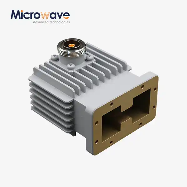 VIEW MOREHigh Power Waveguide to Coaxial Adapter
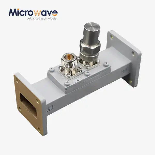 VIEW MOREWaveguide Loop Coupler
 VIEW MOREEnd Launch Double Ridged WG To Coaxial Adapter
 VIEW MOREEnd Launch Waveguide to Microstrip Adapter
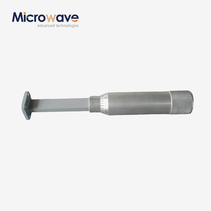 VIEW MOREWaveguide Sliding Termination
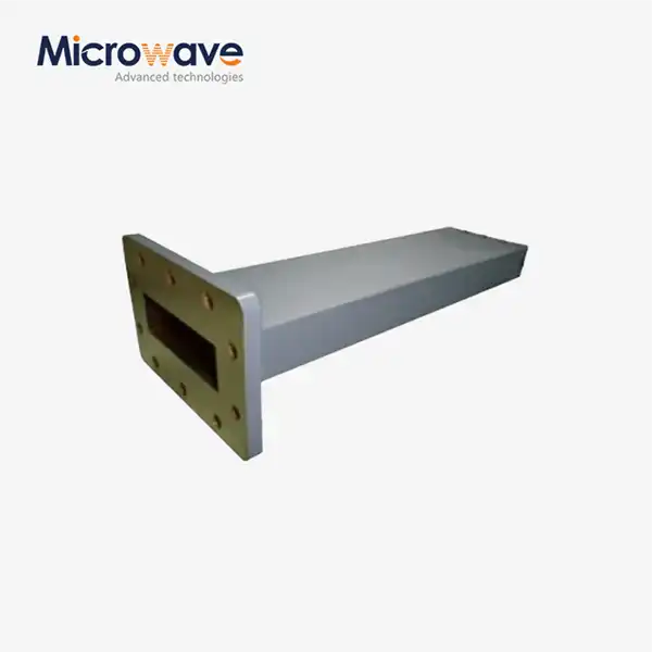 VIEW MOREWaveguide Unmatched Termination
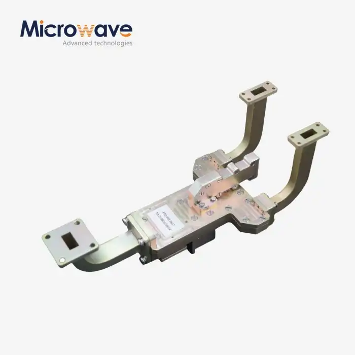 VIEW MOREMagic Hybrid Tee
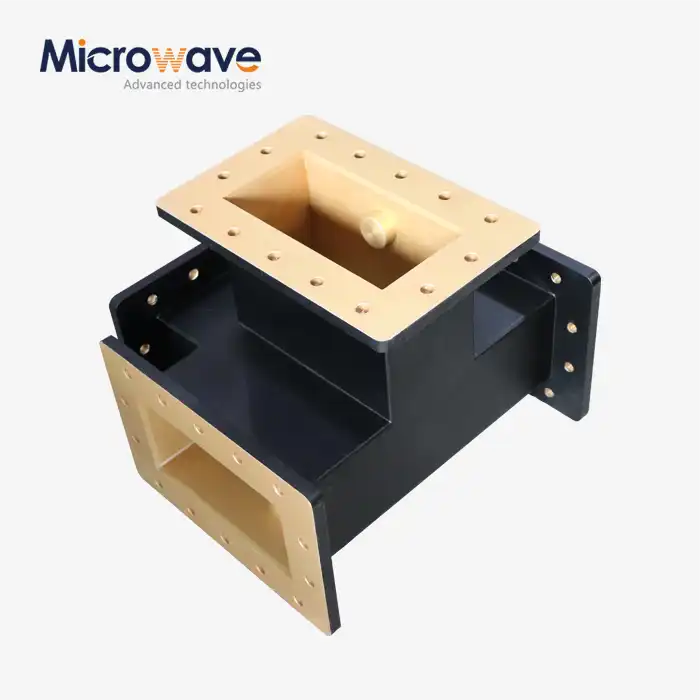 VIEW MOREH-Plane Tee
