


Waveguide Band Stop Filter Performance Optimization
Improving the performance of Waveguide Band Stop Filters is a smart way to make sure that signals in important RF and microwave systems stay intact. The Waveguide Band Stop Filter is a passive part that uses resonant cavity technology to specifically cut down on unwanted frequency bands while keeping the passband sounds very good. This process of optimization includes choosing the right materials, making sure the shapes are correct, managing heat stability, and modeling electromagnetic fields to get rid of sources of interference that slow down the system. Optimized band stop filters provide rejection depths of more than 60 dB with an insertion loss of less than 0.2 dB. This directly leads to better receiver sensitivity and transmitter efficiency in defense radar systems, satellite ground stations, and aerospace communication networks.
Understanding Waveguide Band Stop Filters: Fundamentals and Performance Factors
Waveguide Band Stop Filters work very differently from coaxial or microstrip types because they are made of air-dielectric material and use resonance cavity mechanisms. Band stop designs use shunt-mounted resonators that catch and reflect energy at specific stopband frequencies. This is different from band-pass filters, which let certain frequencies through paired series cavities. This difference in architecture gives it better temperature performance and the ability to handle more power, which are both important for high-reliability uses.
Electromagnetic Principles Governing Filter Operation
Core mechanisms have quarter-wave or half-wave resonant stubs attached to the main waveguide transmission line. The filter short-circuits the stub and main guide when resonance frequency electromagnetic radiation enters. This returns the signal to the source. Frequencies outside the stopband pass through with little loss due to low resistance. Quality factor, or Q, controls rejection bandwidth steepness. Design with greater Q has smaller notch characteristics but tighter production tolerances.
Material Selection Impact on Performance
Material selection affects energy efficiency and operating reliability. Workable and electrically conductive aluminum metal 6061-T6 is ideal for general applications. Copper has reduced resistive losses in high-frequency circuits above 40 GHz. When thermal stability is crucial, use nickel-iron Invar. Since its coefficient of thermal expansion is virtually nil, the stopband center frequency stays within 1 ppm per degree Celsius. However, aluminum changes 23 ppm. Silver or gold plating reduces passband insertion loss from 0.3 to 0.1 dB.
Quality of surface finish matters. Mirror-polished internal sections decrease current congestion and loss, while rounded ends prevent excessive voltage concentration and arcing at high power. We've found that electropolishing and multi-layer silver finishing produce the most consistent results.
Critical Performance Parameters
Insertion loss measures passband signal weakening. It normally ranges from 0.05 to 0.25 dB, depending on filter complexity. Filters with good rejection depth may block 40–80 dB stopband loss. Voltage Standing Wave Ratio (VSWR) measures impedance matching performance. System performance suffers from passband echoes below 1.15:1. Bandwidth requirements list frequencies where rejection is greater than 20 or 30 dB.
Identifying and Overcoming Performance Bottlenecks
To improve performance, you must first take accurate baseline measurements with vector network monitors that have been validated. By measuring S-parameters over a range of temperatures, you can see how they change with temperature, and by testing at high power, you can see voltage breakdown weaknesses that you couldn't see during low-level analysis. Most bottlenecks are caused by inconsistent manufacturing, bad thermal management, or design choices that give up one feature to make another better. This rigorous approach is essential for any high-performance Waveguide Band Stop Filter.
Root Causes of Degraded Performance
Too much insertion loss is often caused by a surface that is rougher than 0.4 microns RMS or a plate that is too thin, less than 3 microns. If the rejection depth isn't enough, it means that the resonators aren't set right or that the coupling aperture has physical mistakes as small as 0.025 mm. Frequency shift shows that the resonator and housing materials don't have the same thermal expansion rate when the temperature changes. When there is a lot of power, sharp edges, or particles that cause electron cascades, multipaction breakdown.

Optimization Techniques and Design Refinements
Tools for electromagnetic modeling, such as HFSS or CST, let you do parametric analysis before making a real prototype. Iterative modeling is used to find the best combinations by changing the resonator insertion depth, iris measurements, and cavity Q-factor. We use temperature compensation by combining materials with different expansion factors. For example, an aluminum housing with Invar resonators keeps the frequency stable from -40°C to +85°C.
Simulation estimates are confirmed by fast CNC machining prototypes, which also show production sensitivities. The tuning screw design lets the frequency be changed after production within ±1% bands. However, production units should be epoxy-locked after testing to keep them stable during vibrations, as required by MIL-STD-810. Modern versions include pressure ports for adding SF6 gas. This increases the power handling from 2 kW to more than 10 kW continuous wave by stopping the insulator from breaking down.
Validation Methodologies
Acceptance testing needs to check how well something works in a real-world setting, not just a controlled lab setting. By switching the thermal chamber between very high and very low temperatures and keeping an eye on the S-parameters, specs are kept across the qualified range. High-power stress tests at 120% of rated CW power for long periods of time find hidden problems. According to military standards, testing for mechanical shock and vibration shows that the structure is solid and that the frequency stays stable under dynamic loads.
Comparative Analysis: Selecting the Right Band Stop Filter for Your Application
When choosing between Waveguide Band Stop Filter, coaxial, and microstrip methods, you have to look at the pros and cons of each for your unique use. Waveguide design is most common in high-power situations with more than 100 watts of power, where coaxial dielectrics break down due to heat. The air-filled transmission path gets rid of worries about dielectric loss and breakdown while also letting more heat escape. Coaxial filters come in small packages that are good for setups with limited room, but they lose power and have higher insertion loss above 18 GHz. Microstrip designs are used in low-power situations where board-level connectivity is more important than speed issues.
Band Stop Versus Band Pass Selection Criteria
Band stop filters are used in radar systems to get rid of sender overtones that can damage sensitive receiver front ends without weakening the main signal. A band stop filter centered at 10 GHz with a 500 MHz bandwidth is used by a C-band pulse radar that makes second and third harmonics to protect the 5 GHz receiver while keeping the send power efficiency high. Band-pass filters, on the other hand, separate wanted data from broadband noise and handle interference in different ways.
Band stop filters are used in broadcast chains at satellite ground stations to stop amplifier false emissions that fall in satellite receive bands that are nearby. This keeps connection power levels stable and stops interference with systems that are close by. To keep friendly emitter frequencies out of military electronic warfare systems, tunable band-stop filters are used. This lets monitoring devices pick up on hostile signals without getting too busy.
Supplier Evaluation Criteria
Leading makers set themselves apart by offering customization options, having a metrology system, and being open about the supply chain. Minimum order amounts show how flexible production can be. For example, experienced suppliers who offer single-unit prototypes show that they are ready to work with engineers, while commodity sellers who need hundred-piece minimums don't. Lead times that range from 6 weeks to 16 weeks can throw off project plans, which is why the ability to speed up production is useful for quick launches.
Credibility is established by certification documents that include material tracking, S-parameter test data, and environmental qualification records. ISO 9001 and AS9100 approvals show that the process is mature, and RoHS compliance makes sure that the product meets all safety standards. Technical support responsiveness during specification development phases predicts service quality after delivery. Transactional sellers are less valuable than providers who offer electromagnetic simulation help and application advice.
Best Practices for Procurement and Integration
The first step in a successful procurement process is turning system needs into exact Waveguide Band Stop Filter specs. Operating frequency ranges, power handling needs, weather conditions, and mechanical interface standards must match stock goods or make custom development necessary. For radar uses that need to send and receive at the same time, stopband rejection must be higher than the receiver desensitization limits + 20 dB.
Specifications for the environment include high temperatures, humidity, resistance to salt fog for marine uses, and the effects of altitude on air breakdown voltage. As per ASTM E595, installations on spacecraft need to be compatible with pressure and outgassing. For electromagnetic compatibility testing, military projects use MIL-STD-461, and for outdoor stress testing, they use MIL-STD-810.
Pricing Structures and Budget Optimization
Catalog goods are priced the same for all uses, while customized solutions have one-time planning fees that can be anywhere from $5,000 to $25,000, based on how complicated they are. Volume price usually starts with discounts of 15–25% for 10 units or more, and goes up to discounts of 40–50% for 100 units or more per year. Long-term contracts with agreed-upon amounts allow for better price and capacity allocation when supplies are low.
There are more costs than just the unit price that make up the total cost of ownership. These include qualification testing costs, integration work, and lifetime support. A cheaper filter that needs a lot of testing and tweaking might end up costing more than a high-end product when it's delivered. We recommend judging providers based on the value they give rather than just their original price. The quality of professional help, the completeness of the documentation, and the terms of the warranty all have a big effect on the success of a program.
Customization and Lead Time Management
When needs match standard frequency bands and power levels, 60 to 70% of uses can be met by off-the-shelf goods. When there are unusual frequency combos, harsh environmental conditions, or unique mechanical connections, custom designs are needed. Prototyping takes between 4 and 6 weeks, and then performance testing and design changes happen. Getting production tools adds two to three weeks to the time it takes to start mass production.
Due to tight plans, there are times when paying 30–50% more for parallel workflow steps instead of linear ones is worth it. Supply disruptions can be lessened by keeping a buffer stock of long-lead items. Critical programs often buy 110–120% of the estimated amounts to account for loss of supplies and unexpected failures.
Supplier Credibility Verification
Due diligence checks include looking at the building itself, the quality control system, and getting references from past customers. Instead of giving average numbers without statistical confidence levels, datasheets should list the conditions and limits of the measurements. In addition to the manufacturer's own certification, third-party test results from accredited labs offer extra security.
Transparency in the supply chain shows any possible single-source dependencies or global risks that could stop operations. Making things in the United States may cost more, but it gets rid of the problems that come with importing things and makes sure that they are ITAR-compliant for security uses. Dual-source strategies try to find the best mix between lowering costs and making sure there is enough supply. However, because waveguide filters are custom, they can't always be switched between sources perfectly.
Future-Oriented Strategies for Waveguide Band Stop Filter Utilization and Development
New electromagnetic simulation tools allow first-pass design success rates of more than 85% by using multi-physics models that include electromagnetic, mechanical, and thermal reactions all at the same time. Machine learning algorithms can now improve cavity shapes faster than traditional parametric sweeps by taking into account dozens of factors. This cuts development times from months to weeks. Cloud-based modeling systems make advanced tools available to more people than they were before, when they needed specialized workstations. This evolution is critical for the next generation of Waveguide Band Stop Filter technology.
Industry Trends Driving Specification Evolution
5G millimeter-wave operations move working frequencies into the V-band and W-band, which are more likely to be absorbed by the atmosphere and lose components. For these uses, band-stop filters need to have insertion loss below 0.15 dB and rejection above 50 dB. To meet these requirements, the parts must be precisely machined with tolerances of less than 10 microns and plated with valuable metals multiple times. Modernization plans for radar switch from mechanically scanned arrays to active electronically scanned arrays. This means that filtering needs are spread out over hundreds of transmit/receive units, which means that space and weight restrictions get tighter.
Co-frequency interference problems are caused by satellite megaconstellations with thousands of spacecraft, which need adaptive filters. In the future, designs might include MEMS-tuned resonators that let stopbands be changed electrically instead of having to be adjusted mechanically. IoT sensor networks that work in busy ISM bands need tiny filters that balance performance and cost, which is pushing material science to create new low-loss dielectrics and additive manufacturing methods.
Sustainable Manufacturing Approaches
As providers switch from hexavalent chromate conversion coatings to trivalent options that meet RoHS guidelines, environmental responsibility affects the materials they choose. Silver recovery programs take valuable metals out of industrial waste streams and use them again. This saves money on materials and is better for the earth at the same time. Advanced toolpath optimization and energy-efficient CNC machine tools reduce carbon footprints without affecting the accuracy of measurements.
Design choices are now based on lifecycle assessments, which favor systems that can be fixed over parts that can be thrown away. Modular resonator assemblies enable field servicing rather than complete unit replacement, extending operational life from 10 years to 20+ years in satellite ground infrastructure. These efforts to be more sustainable are good for the environment and lower the total cost of ownership.
Conclusion
To make the Waveguide Band Stop Filter work better, you need to find a balance between electromagnetic theory, material science, precision manufacturing, and smart purchasing. The technical world needs people who are good at designing resonant cavities, managing heat, figuring out how to handle power, and putting systems together. Procurement experts do their jobs well when they form relationships with manufacturers that offer technical collaboration, quality certifications, and quick help throughout the lifecycle of a product. As 5G networks grow, radar systems get updated, and the number of satellite groups grows, optimized band-stop filters will continue to be essential for mission-critical apps to keep signals safe. Putting money into new filter technologies in a smart way now will give you a competitive edge and make your business more reliable tomorrow.
FAQ
Q1: How does a waveguide band stop filter differ from a band pass filter in radar applications?
Waveguide Band Stop Filters block certain frequencies of interference while letting wanted signals through. This keeps listeners safe from transmitter harmonics. Broadband noise is separated from the information that you want by band-pass filters. Band-stop filters are used in the broadcast chains of radar systems, and band-pass filters are used in the receiving front ends. These two types of filters work together to handle interference.
Q2: What factors contribute most to insertion loss in the passband?
Insertion loss is mostly caused by surface roughness, plate conductivity, and internal irregularities. When multi-layer silver plating is used on surfaces that are mirror-polished, and less than 0.2 microns RMS, losses are less than 0.1 dB. When it comes to high frequencies, copper works better than aluminum, and good joint casting stops resistive losses at flange surfaces.
Q3: Can waveguide band stop filters be customized, and what are typical lead times?
Customization takes into account different frequency combinations, power levels, environmental needs, and mechanical connections. It takes 4 to 6 weeks to make a prototype, which includes electromagnetic models and validation tests. For custom designs, the total wait time is 8–12 weeks, while for catalog goods, it's only 3–4 weeks. This is because production tooling takes an extra 2–3 weeks before mass production.
Partner with ADM for Superior Waveguide Band Stop Filter Solutions
Advanced Microwave Technologies Co., Ltd. offers designed Waveguide Band Stop Filter options and has been making RF components for 20 years. Our ISO 9001-certified manufacturing methods and 24-meter anechoic room make it possible to test performance at every stage, from prototyping to production. Our technical team works together to make sure that speed, cost, and delivery times are all optimized, whether you need catalog goods that can be used right away or custom-engineered filters that meet exact specs. Defense companies, satellite operators, and telecommunications developers hire us to provide them with ruggedized parts that meet MIL-STD and aerospace qualification standards. You can talk to our engineering staff about your needs, get detailed datasheets, or ask for trial samples by emailing craig@admicrowave.com. As a reliable waveguide band stop filter maker, we turn your needs into solid solutions that help your goal succeed.
References
1. Matthaei, G.L., Young, L., and Jones, E.M.T. "Microwave Filters, Impedance-Matching Networks, and Coupling Structures." Artech House Publishers, 1980.
2. Pozar, David M. "Microwave Engineering, 4th Edition." John Wiley & Sons, 2012.
3. Levy, Ralph. "Filters for Communications Satellites." IEEE Microwave Magazine, Vol. 12, No. 6, 2011.
4. Cameron, Richard J., Kudsia, Chandra M., and Mansour, Raafat R. "Microwave Filters for Communication Systems: Fundamentals, Design, and Applications." Wiley-Interscience, 2007.
5. Hunter, Ian C. "Theory and Design of Microwave Filters." IET Electromagnetic Waves Series, 2001.
6. Craven, George F. and Skedd, Richard F. "Evanescent Mode Microwave Components." Artech House Microwave Library, 1987.
YOU MAY LIKE
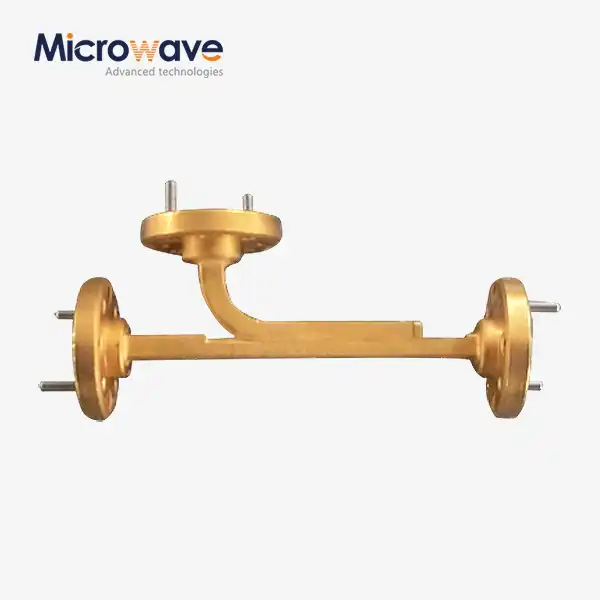 VIEW MOREBroadwall Directional Coupler
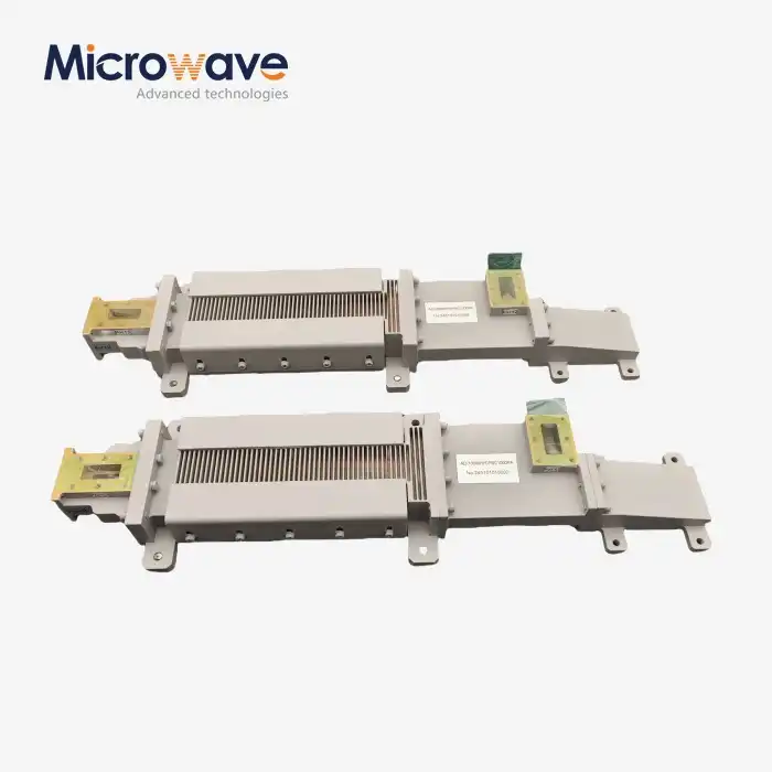 VIEW MOREWG Circulator
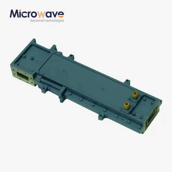 VIEW MOREHigh Power Waveguide Differential Phase Shift Circulator
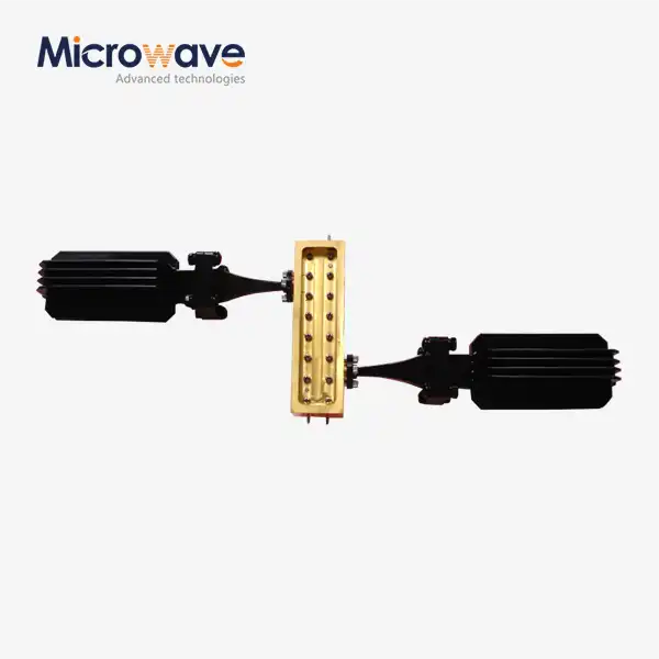 VIEW MOREWaveguide Coupling Fixed Attenuator
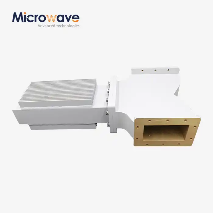 VIEW MOREWG Isolator
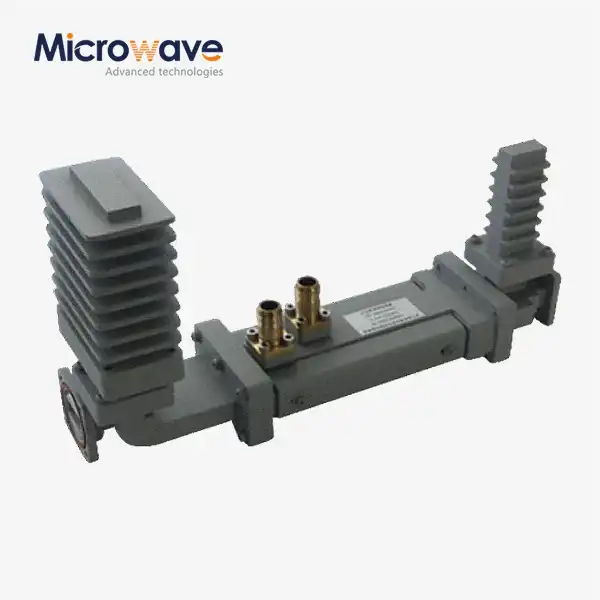 VIEW MOREHigh Power Waveguide Differential Phase Shift Isolator
 VIEW MOREWG Band Stop Filter
 VIEW MOREWG Low Pass Filter
