From WR-90 to SMA: Waveguide to Coaxial Adapter Explained
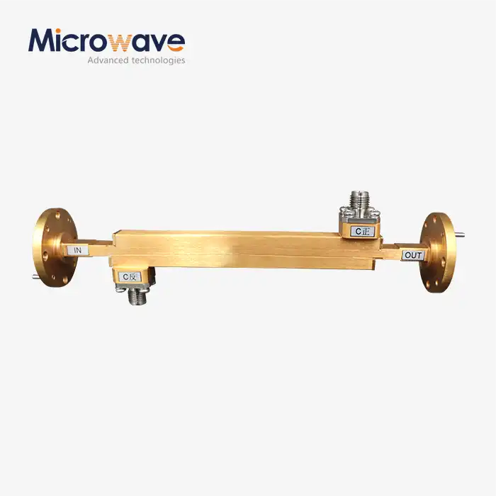
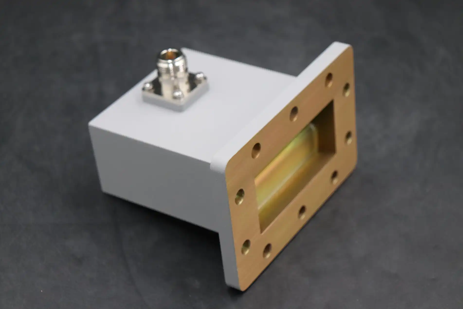
If you work in RF system design or technical procurement, you already know that signal transitions matter. A waveguide to coaxial adapter is the passive component that bridges the gap between a rectangular waveguide port — such as the WR-90 — and a coaxial connector like the SMA. It converts the dominant TE10 mode inside the waveguide into the TEM mode of the coaxial line. Get this transition wrong, and you face impedance mismatch, elevated VSWR, and degraded system performance. Get it right, and your X-band chain runs at peak efficiency.
Understanding Waveguide to Coaxial Adapters
What the WR-90 Designation Means
The WR-90 is a normal rectangular waveguide that is 0.900 inches long and 0.400 inches wide on the inside. It works in the X-band frequency range of 8.2 to 12.4 GHz, which makes it one of the most common waveguide sizes used in radar, satellite ground stations, and test equipment. The word "WR" stands for "Waveguide Rectangular," and the number is the width in hundredths of an inch.
The Role of the SMA Connector
The SMA (SubMiniature version A) connector is a threaded coaxial interface that can handle up to 18 GHz in its standard form. More precise versions can handle up to 26.5 GHz. Its small size and 50-ohm impedance make it the standard choice for connecting WR-90 waveguide sections to coaxial cable assemblies, test port connections, or low-noise amplifier inputs in X-band systems.
Key Electrical Specifications to Verify
Before engineers choose an adapter, they should make sure of three things. First, let's talk about VSWR. A WR-90 to SMA adapter that is well-made should have a VSWR of less than 1.25:1 across the whole X-band. The second thing is insertion loss. Normal numbers are less than 0.3 dB, and high-precision units can hit 0.15 dB. Third, how much power they can handle: standard SMA-based adapters can handle up to 100 W on average at lower X-band frequencies. However, this drops as the frequency and temperature rise.
Comparing Waveguide to Coaxial Adapters: Making the Right Choice
Waveguide-to-Coax vs. Coax-to-Waveguide: Is There a Difference?
Electrically, these two names refer to the same physical thing; signals can go either way through the structure because it is inactive. The difference is just a matter of name convention based on the direction of data flow. The term "coax-to-waveguide" is used by engineers when the coaxial port is the input, like when they connect a signal generator, and "waveguide-to-coax" is used when the waveguide is the source. One part can be used for both situations.
Reading a Datasheet for Signal Integrity
Instead of just looking at a single frequency VSWR number on a datasheet, look for sweep return loss data across the whole working band. If the return loss is 20 dB or less between 8.2 and 12.4 GHz, it means that the reflected power is less than 1% of the incident power, which is fine for most system budgets. Also, make sure that the insertion loss numbers are only calculated at room temperature, since thermal drift can add 0.05 to 0.10 dB at higher temperatures.
Price vs. Performance for X-Band Adapters
Standard WR-90 to SMA waveguide to coaxial adapters with silver-plated metal cores are sold by a number of companies at prices that most people can afford. Gold-plated brass models cost more, but they last longer and don't rust in places with salty or wet air. For lab-level testing or phased-array assembly, precision-machined copper versions with tighter physical tolerances offer lower VSWR and are worth the extra cost compared to catalog-grade parts.
Applications and Advantages of WR-90 to SMA Adapters
There are a lot of different uses for the WR-90 to SMA connector because X-band signals are used in so many important systems. X-band transitions must be reliable for defense radar, satellite uplink chains, weather Doppler systems, and surveillance platforms in the air. In the main situations where these adapters clearly add scientific value, they work like this:
- Radar front-end connections: In ground-based and shipboard radar, the adapter connects the waveguide run from the antenna feed to coaxial-input LNAs or frequency converters. Insertion loss below 0.3 dB at this point directly improves receiver noise figure, which translates to longer detection range.
- Satellite ground station test access: Test engineers insert WR-90-to-SMA adapters as access ports on uplink chains during pre-transmission verification. The SMA interface connects to a VNA or spectrum analyzer without breaking the waveguide path permanently.
- OEM module integration: When OEM manufacturers design compact transceiver modules for UAVs or electronic warfare systems, they use these adapters to translate the waveguide output from a traveling-wave tube amplifier into a coaxial interface for the downstream signal distribution network.
All of these uses have one thing in common: the adapter has to keep the signal quality even when the temperature changes, the device shakes, and it mates and disconnects many times. A bad unit adds echoes that spread through the system, creating standing waves that lower the efficiency of power transfer and can put heat stress on nearby parts.
Procurement Guide for B2B Clients: Buying and Customizing RF Transitions
When a Standard Part Is Sufficient
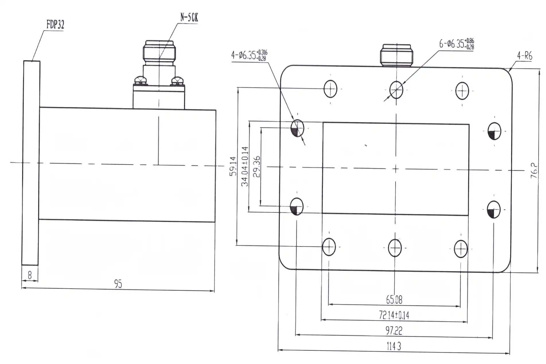
A standard WR-90 to SMA adapter with a CPR90G or UBR100 flange is enough for most X-band system builds. Standard parts are ready to ship in days, come with released test data, and fit into mechanical boxes that are already in place. Before placing an order, procurement teams should make sure they know the flange bolt pattern, the gender of the connector (male or female SMA), and the body orientation (end-launch vs. broadside-launch).
When Custom Design Becomes Necessary
Custom designs are needed when the frequency range goes beyond 12.4 GHz, when the power handling is more than 500 W CW, when the mechanical envelope limits where the flange can be placed, or when pressurized waveguide runs need airtight closing. If a provider has their own machining and RF modeling tools, they can make a probe-launch geometry that is tuned to the exact working band and has VSWR below 1.15:1 over a narrow bandwidth.
Supply Chain and Lead Time Considerations
Standard waveguide to coaxial adapters are usually shipped in bulk within two to four weeks from the time they are stocked. It takes four to eight weeks to create, build, and test a prototype of a custom unit. Ask for S-parameter data files (Touchstone.s2p format) with every order so that your models match the hardware that has been tested. For defense and aerospace procurement cycles, you must make sure that the supplier is ISO 9001 certified and can provide material traceability documentation.
Leading Suppliers in the WR-90 to SMA Adapter Market
Established Catalog Suppliers
Pasternack and Huber+Suhner keep a large inventory of WR-90 to SMA adapters with published data on VSWR and insertion loss. For measurement and calibration-level uses, Flann Microwave specializes in making precise waveguide parts. Teledyne makes adapters that meet military environmental standards, such as the MIL-STD-202 shock and vibration profiles. Because each supplier is trying to reach a different price-performance segment, procurement teams are better off asking for competitive quotes based on specifications that are the same, rather than just asking about brand preference.
Evaluating a Supplier Beyond the Catalog
How a seller handles requests that aren't typical shows how valuable it really is. Some important signs are how quickly you respond to technical questions, how ready you are to share raw VNA measurement data (not just pass/fail certificates), how easy it is to get engineering help during design integration, and how much experience you have with systems like this. ISO 9001 and RoHS compliance are basic standards. Suppliers who work with military or defense customers should also show that they know how to follow environmental test standards.
Where ADM Fits in This Landscape
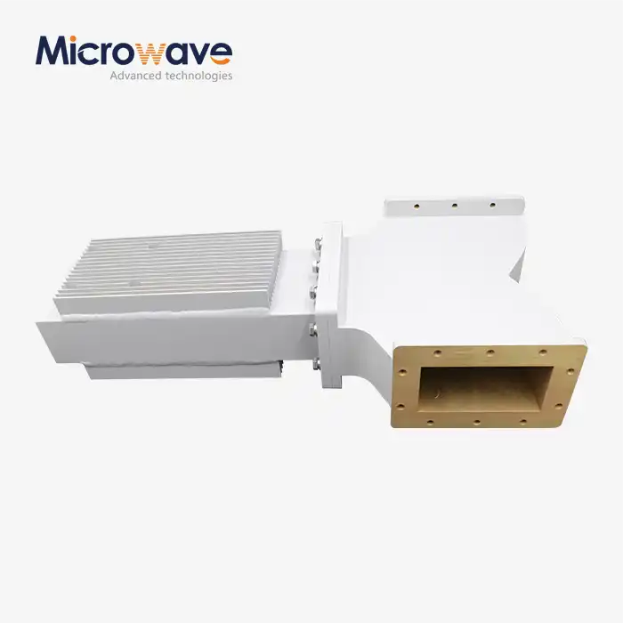
Advanced Microwave Technologies (ADM) has a full line of waveguide-to-coaxial transitions and complementary components. One of these is its High Power Waveguide Isolator line, which comes in Al/Cu construction, can handle up to 1,000 W of forward power, has 20 dB of isolation, 0.3 dB of insertion loss, and an 800 MHz operational bandwidth across a temperature range of –40°C to +70°C. Getting both the adapter and the isolator from the same supplier makes managing the bill of materials easier and ensures that all the parts that connect to each other work well mechanically.
Conclusion
The change from WR-90 to SMA is a small part that has a big effect on how well the system works. Not just price should be taken into account when picking the right waveguide to coaxial adapter. VSWR, insertion loss, power limit, flange type, and mechanical alignment are also important. If you need a standard catalog part for quick integration or a custom-designed unit for a sealed defense application, make sure you buy from a seller whose RF measurement skills have been checked and who has quality certification. This will protect your system design from the very beginning. ADM can meet both standard and unique needs, and all of their parts are backed by over 20 years of manufacturing experience and recorded performance data.
FAQ
What frequency range does a WR-90 to SMA adapter cover?
The WR-90 waveguide works in the X-band, which is 8.2 to 12.4 GHz. This range is well supported by the SMA connector, which has a maximum frequency of 18 GHz. This makes the connection ideal for X-band radar, satellite, and test uses.
What VSWR should I expect from a standard WR-90 to SMA adapter?
A normal unit that is properly built has VSWR less than 1.25:1 across the whole X-band. Versions that are more precise or made for laboratories can go below 1.15:1 over a smaller bandwidth.
Can I use the same adapter for both transmit and receive paths?
Yes. In terms of how signals move physically, the adapter is a passive, two-way device. It can be used on either path, but when putting it on a send chain, you should always check the power handling rates.
What is the difference between an end-launch and a broadside-launch adapter?
In an end-launch, the SMA connection is placed along the broad-wall line of the waveguide, and in a broadside-launch, it is placed perpendicular to the length of the waveguide. Which one you choose will depend on how your hardware is set up and how much space you have around the waveguide port.
Does ADM offer custom WR-90 to SMA adapters?
Yes, ADM can make OEM designs for non-standard frequency bands, ports that have been changed, and specific power levels. To get a technical consultation and prototype evaluation, send your specifications to craig@admicrowave.com and get in touch with the engineering team.
Partner With ADM for Your Next Waveguide to Coaxial Adapter Project
ADM makes reliable waveguide to coaxial adapters and has been doing so for more than 20 years. They are ISO 9001 certified and follow RoHS guidelines when making their products. Our engineering team helps with projects from the first set of requirements to testing the prototype and making a lot of them. We can quickly make a normal X-band adapter or a custom-engineered transition for a tough defense or satellite application, and we'll give you full measurement paperwork. To start talking right away, send your requirements to craig@admicrowave.com.
References
1. Pozar, D. M. Microwave Engineering, 4th ed. Wiley, 2011.
2. Montgomery, C. G., Dicke, R. H., & Purcell, E. M. Principles of Microwave Circuits. MIT Radiation Laboratory Series, McGraw-Hill, 1948.
3. IEEE Standard 1785.1-2012. IEEE Standard for Rectangular Metallic Waveguides and Their Interfaces for Frequencies of 110 GHz and Above. IEEE, 2012.
4. Collin, R. E. Foundations for Microwave Engineering, 2nd ed. IEEE Press / Wiley-Interscience, 2001.
5. Matthaei, G., Young, L., & Jones, E. M. T. Microwave Filters, Impedance-Matching Networks, and Coupling Structures. Artech House, 1980.
6. MIL-DTL-3922/67. Detail Specification: Connector, Coaxial, Radio Frequency, Subminiature, SMA Series. U.S. Department of Defense, 2003.