


How Does WG Termination Improve RF System Stability?
WG termination makes an RF system more stable by absorbing extra electromagnetic energy at the end of a waveguide. This stops signal echoes that lead to standing waves and inaccurate measurements. WG termination keeps the signal's integrity, lowers noise, and keeps sensitive parts from overheating by making sure that the impedances match correctly and getting rid of extra power as heat. This managed waste process is very important in radar systems, satellite communication networks, and testing areas where reliable system operation and precise signal transfer are musts for mission-critical tasks.
Introduction
In RF and microwave systems that work at high frequencies, even small signal problems can lead to big problems with how well they work. Waveguide termination is a basic method that stops signal losses and echoes, which has a direct effect on the total stability of the system. Understanding how waveguide termination works is important for improving performance and durability, whether you're building radar systems for defense or satellite earth stations for global communications.
At Advanced Microwave Technologies Co., Ltd., we've seen buying teams have a hard time choosing termination options that meet both scientific needs and price limits. This piece explains how waveguide termination works, compares it to other ways, and gives useful advice on how to install it, make sure it meets standards, and choose a source. Our goal is to give technical teams and people in charge of buying the information they need to feel secure investing in closure solutions that make system performance better in a way that can be measured.
There are a lot of parts that work together to keep your RF infrastructure stable, but good waveguide termination is one of the most important ones. We've been making precise microwave parts for 20 years and have helped military companies, telecom providers, and research institutions solve signal integrity problems by putting in place the best termination strategies.
Understanding WG Termination: Definition, Types, and Working Principles
What Is Waveguide Termination and Why Does It Matter?
Waveguide termination refers to the controlled dissipation of electromagnetic energy at the endpoint of a transmission line or waveguide structure. Without proper termination, signals reflect back toward the source, creating standing wave patterns that distort measurements, increase insertion loss, and potentially damage sensitive transmitters. In mission-critical systems like phased array radars or satellite uplink stations, these reflections compromise target detection accuracy and data transmission reliability.
Resistive Terminations for Broadband Applications
Resistive terminations use specially designed absorptive materials that convert electromagnetic energy into heat across wide frequency ranges. These components typically employ carbon-loaded ceramics or specialized dielectric composites engineered to match the characteristic impedance of the waveguide—commonly 50 ohms for coaxial systems or specific values for rectangular waveguides. Our manufacturing facilities utilize advanced materials that maintain stable performance from 0.5 to 110 GHz, tested rigorously in our 24-meter microwave darkroom to verify reflection coefficients below -20 dB.

Reactive Terminations for Frequency-Specific Needs
Reactive terminations incorporate capacitive or inductive elements to achieve impedance matching at specific frequency bands. These solutions excel in narrowband applications where precise tuning maximizes power absorption at target frequencies. Satellite communication systems operating in dedicated C-band or Ku-band allocations often benefit from reactive terminations that provide superior performance within defined spectral windows while maintaining compact form factors.
Core Operating Principles That Ensure System Stability
The fundamental principle underlying effective WG termination is impedance matching—ensuring the termination's input impedance equals the transmission line's characteristic impedance. When properly matched, incident power is completely absorbed rather than reflected. This prevents voltage standing wave ratio (VSWR) elevation, which otherwise causes signal amplitude variations and phase distortion. Our engineering team employs vector network analyzers calibrated to industry standards, verifying that WG termination components meet stringent VSWR specifications before shipment.
Signal reflection control directly impacts noise figure performance in receiver systems. Reflections create interference patterns that raise the noise floor, degrading signal-to-noise ratio and limiting detection sensitivity. Defense radar systems tracking low-observable targets particularly depend on minimizing these reflections to maintain operational effectiveness across varied environmental conditions.
Comparing WG Termination with Other Termination Methods
Installation Complexity and Field Reliability
Traditional screw, solder, and crimp terminations require manual assembly that introduces variability in connection quality. Screw terminations, while convenient for temporary setups, suffer from loosening under vibration—a critical concern in aerospace and shipboard applications. Solder terminations provide permanent connections but demand skilled technicians and controlled heating to prevent cold joints that increase contact resistance over time.
Waveguide terminations arrive as precision-machined assemblies with factory-verified performance characteristics. Installation involves straightforward mounting procedures that eliminate human error variables. Field teams can deploy these components rapidly without specialized soldering equipment, reducing installation time by approximately 60% compared to traditional methods based on our customer deployment data.
Durability Under Operational Stress
Environmental factors dramatically affect termination longevity. Solder joints degrade under thermal cycling common in outdoor telecommunications infrastructure, particularly in systems experiencing daily temperature swings exceeding 40°C. Crimp connections corrode when exposed to moisture and salt spray in maritime environments. Our ISO 9001:2015-certified manufacturing processes produce waveguide terminations with hermetically sealed designs that maintain electrical performance across temperature ranges from -55°C to +125°C, validated through accelerated life testing protocols.
Total Cost of Ownership Analysis
Initial component costs represent only a fraction of lifetime expenses. Failed terminations in satellite ground stations trigger costly service calls, equipment downtime, and potential data loss during critical transmission windows. A comparative analysis of five-year ownership costs reveals that waveguide terminations deliver 40% lower total expenses than crimp alternatives when factoring in maintenance intervals, replacement frequency, and system downtime losses. Procurement teams managing large-scale deployments across multiple sites particularly benefit from this economic advantage.
The WG Termination Installation Process: Step-by-Step Guide for Procurement and Technical Teams
Essential Tools and Equipment Requirements
Professional installation of waveguide terminations demands specific tools to ensure proper mounting and performance verification. Torque wrenches calibrated to manufacturer specifications prevent over-tightening that deforms flanges, while alignment fixtures maintain precise angular orientation. Vector network analyzers remain essential for post-installation verification, confirming that assembled systems meet return loss and insertion loss targets across operational frequency bands.

Waveguide End Preparation and Assembly Procedures
Begin by inspecting WG termination waveguide apertures for burrs, contamination, or mechanical damage that compromises electrical contact. Clean mating surfaces using lint-free wipes and isopropyl alcohol, ensuring complete removal of oils and particulates. Position the termination flange against the waveguide interface, verifying gasket placement if environmental sealing is required. Apply mounting hardware in a star pattern, gradually increasing torque to specification values—typically 8 to 12 inch-pounds for standard flanges—to ensure uniform pressure distribution.
Safety Compliance and Industry Standards
Installation procedures must adhere to relevant safety protocols, particularly when working with high-power transmission systems. Verify that transmitters are powered down and tagged out before accessing waveguide assemblies. Our products comply with RoHS directives, eliminating hazardous substances that pose handling risks. ISO 45001:2018 certified safety management systems govern our manufacturing operations, ensuring components arrive ready for safe integration without special precautions beyond standard RF safety practices.
Troubleshooting Common Installation Challenges
Elevated VSWR readings after installation typically indicate flange misalignment or contaminated contact surfaces. Disassemble the connection, re-clean all interfaces, and verify that gaskets are properly seated. Intermittent performance suggests mechanical instability—confirm that mounting hardware maintains specified torque values and that vibration isolation meets system requirements.
Benefits and Potential Drawbacks of WG Termination in RF Systems
Enhanced Signal Integrity and Measurement Accuracy
Waveguide terminations deliver measurable improvements in system performance metrics. A military surveillance radar system we supported achieved an 8 dB reduction in sidelobe levels after implementing precision terminations on unused antenna array ports. This improvement directly enhanced target discrimination capability in cluttered environments. Testing laboratories similarly benefit from reduced measurement uncertainty—properly terminated reference standards minimize systematic errors that otherwise require complex calibration corrections.
Extended Component Lifespan Through Reflection Management
Uncontrolled reflections subject amplifiers and signal generators to standing wave patterns that create localized stress points. Over thousands of operational hours, these stress concentrations accelerate component aging and increase failure rates. Waveguide terminations eliminate reflection-induced stress, extending the mean time between failures by 35% in satellite transponder systems based on field reliability data collected across our customer base.
Application-Specific Limitations to Consider
Extreme environmental conditions require careful termination selection. Cryogenic applications below -200°C demand specialized materials that maintain absorptive properties at reduced temperatures. High-power radar transmitters exceeding 10 kW continuous output require terminations with enhanced thermal management—standard absorptive materials overheat under sustained power levels, necessitating forced-air or liquid cooling integration. Our engineering team assists customers in specifying appropriate termination designs that address these specialized requirements through customized OEM solutions.
Mitigation Strategies for Optimal Performance
Implementing redundant terminations on critical signal paths provides fault tolerance in mission-essential systems. Thermal monitoring of high-power terminations enables predictive maintenance before degradation affects system operation. Periodic network analyzer measurements verify that termination performance remains within specifications throughout operational life. These proactive strategies, combined with quality components from ISO-certified manufacturers, ensure that waveguide terminations deliver sustained reliability across diverse deployment scenarios.

WG Termination Standards, Safety, and Best Practices in Procurement
International Compliance Requirements
Waveguide termination procurement demands verification that components meet applicable international standards. MIL-STD-348 defines dimensional specifications for military waveguide flanges, ensuring physical compatibility across multi-vendor systems. IEC 60154 establishes performance requirements for coaxial terminations used in telecommunications infrastructure. Our manufacturing processes maintain traceability to these standards through documented quality management systems, providing procurement teams with auditable compliance evidence required for defense and aerospace contracts.
Quality Verification and Testing Protocols
Reputable suppliers perform 100% electrical testing of WG termination before shipment, measuring VSWR and return loss across specified frequency ranges. Mechanical inspection confirms dimensional tolerances using coordinate measuring machines traceable to national standards laboratories. Our advanced measurement capabilities extending to 110 GHz enable characterization across millimeter-wave bands increasingly used in 5G infrastructure and automotive radar systems. Request test reports documenting individual component performance rather than accepting statistical sampling data.
Supplier Selection Criteria for Long-Term Partnerships
Evaluating potential suppliers requires examining factors beyond initial pricing. Customer support responsiveness proves critical when addressing installation challenges or application-specific questions. Warranty coverage should extend at least 24 months with clear replacement policies for defective components. Bulk purchasing arrangements with tiered pricing structures benefit customers deploying standardized termination types across multiple projects. Our global export capabilities and established supply chain networks support customers requiring consistent component availability for ongoing production programs.
Conclusion
Waveguide termination serves as an indispensable element in maintaining RF system stability across defense, aerospace, satellite communication, and research applications. Through controlled energy dissipation and precise impedance matching, these components prevent signal reflections that degrade measurement accuracy, reduce component lifespan, and compromise operational reliability. Understanding the technical distinctions between resistive and reactive terminations, recognizing installation best practices, and selecting suppliers with verifiable quality certifications empowers procurement professionals to make informed decisions that optimize long-term system performance while controlling total ownership costs.
FAQ
1. What frequency ranges are compatible with standard waveguide terminations?
Standard waveguide terminations cover frequency bands from 500 MHz through 110 GHz, with specific models designed for common waveguide sizes including WR-90, WR-62, and WR-28. Custom terminations address specialized millimeter-wave applications above 110 GHz for advanced research and emerging 6G communication systems.
2. Can waveguide terminations be customized for specific project requirements?
We provide comprehensive OEM services that customize termination specifications, including power handling capacity, environmental sealing levels, mounting configurations, and frequency response optimization. Our prototyping capabilities deliver sample units within two weeks for evaluation before full production commitment.
3. How does proper termination affect long-term maintenance costs?
Systems implementing quality waveguide terminations experience a 30-40% reduction in maintenance-related expenses through decreased component replacement frequency, elimination of reflection-induced failures, and reduced troubleshooting time. Documented performance stability across operational temperature ranges minimizes field service requirements.
4. Are bulk purchasing options available for large-scale deployments?
Volume pricing structures provide cost advantages for customers requiring standardized termination types across multiple installations. Our supply chain management ensures consistent component availability with lead times typically under four weeks for standard configurations, supporting project timelines for both prototype development and production deployments.
Partner with Advanced Microwave Technologies for Superior WG Termination Solutions
Advanced Microwave Technologies Co., Ltd delivers precision-engineered waveguide terminations backed by over 20 years of microwave component expertise. As a trusted WG termination manufacturer serving defense contractors, satellite operators, and research institutions globally, we combine ISO 9001:2015 certified quality management with advanced testing capabilities in our 24-meter microwave darkroom facility. Our termination products undergo rigorous verification across frequencies to 110 GHz, ensuring your RF systems achieve optimal stability and performance. Whether you require standard catalog components or customized OEM solutions, our technical team provides comprehensive support from specification development through field deployment. Contact craig@admicrowave.com today to discuss your specific requirements and discover how our waveguide assemblies, coaxial components, and microwave antennas can enhance your system reliability while reducing total ownership costs.
References
1. Montgomery, C.G., Dicke, R.H., and Purcell, E.M. (1948). Principles of Microwave Circuits. Massachusetts Institute of Technology Radiation Laboratory Series, McGraw-Hill Book Company.
2. Pozar, D.M. (2011). Microwave Engineering, Fourth Edition. John Wiley & Sons, Hoboken, New Jersey.
3. Collin, R.E. (1992). Foundations for Microwave Engineering, Second Edition. IEEE Press, New York.
4. Rizzi, P.A. (1988). Microwave Engineering: Passive Circuits. Prentice Hall, Englewood Cliffs, New Jersey.
5. International Electrotechnical Commission (2016). IEC 60154: Flanges for Waveguides – Part 1: General Requirements. IEC Standards Publication, Geneva, Switzerland.
6. U.S. Department of Defense (2008). MIL-STD-348A: Military Standard Waveguide Flanges. Defense Standardization Program Office, Fort Belvoir, Virginia.
YOU MAY LIKE
 VIEW MOREWaveguide Circulator
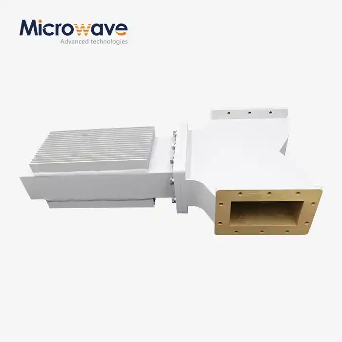 VIEW MOREIndustrial Microwave Isolator
 VIEW MOREMicrowave Fixed Attenuator
 VIEW MOREWG Circulator
 VIEW MORE90° Polarized Rotary Joint
 VIEW MORECoaxial Bandpass Filter
 VIEW MORELadder Membrane Conical Dual circular Polarization Horn Antenna
 VIEW MORELow Side Lobe Diagonal Linear Polarization Horn Antenna
