How Does an E-Plane Tee Split Microwave Signals Efficiently?
The E-Plane Tee is one of the most important waveguide parts in modern microwave engineering. It divides electromagnetic signals very well and lets you manage their phase very well. This three-port junction, which is also called a "series tee," makes the phase difference between the output signals 180 degrees. This makes it essential for tasks that need accurate signal reduction and processing that depends on phase. When purchasing, engineers and technical buying teams have to choose high-frequency components; they need to know how this device works and why it's better than other options in some situations. This is important for making sure that the system is reliable and performs well. In the military, aircraft, satellite communications, and telecommunications industries, this guide is useful for purchase managers, RF experts, and system designers. We look at the basic ideas behind how they work, compare their performance to other parts, and look at real-life situations where these gadgets provide measured benefits. We give your company more than just technical specs; we also give you practical buying strategies to help you find approved, high-performance waveguide components that meet the strict requirements of mission-critical systems. When you're done with this guide, you'll know enough to confidently make purchases that improve both signal accuracy and operating efficiency.
Understanding the Fundamentals of E-Plane Tee
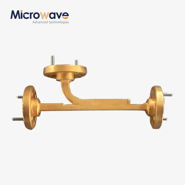
The E-Plane Tee is a special kind of three-port waveguide joint. The extra side arm lines up with the main collinear waveguide's electric field plane. When a microwave signal comes in through the side arm (Port 3), the electromagnetic energy is split evenly between two ports that are next to each other (Port 1 and Port 2). However, the output signals have the same size but a 180-degree phase difference, which makes them stand out. This anti-phase behavior makes signal reduction possible naturally, so in many circuit designs there is no need for additional phase shifters.
Basic Operating Principles and Signal Distribution
The electric behavior of this part is determined by its physical shape. When the side arm connects to the wide wall of the rectangular waveguide, the electric field spreads out and forces current to flow in opposite directions at the two output ports. This happens because the junction makes an electrical series link, which means that the mirrored waves from each output port overlap in a bad way along the main axis and help it along the side arm. Because the structure is symmetrical, the power split stays balanced. When made and matched correctly, it usually achieves better than 0.2 dB amplitude balance.
Material Selection and Construction Standards
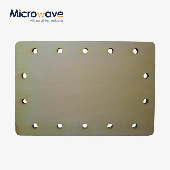
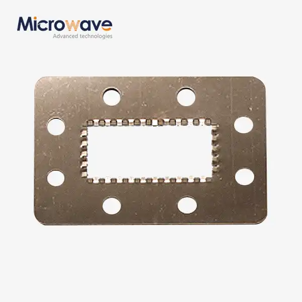
Paying close attention to the features of the materials and the limits for sizes is necessary to make these parts. Oxygen-Free High Conductivity (OFHC) copper and aluminum alloy 6061-T6 are the most common materials used because they are good at conducting electricity and can be easily machined. Silver or gold plating with a thickness of 3 to 5 micrometers is usually used for surface finishing. This reduces skin-effect losses at high frequencies. To keep performance from dropping with frequency, the internal measurements must meet standards like WR-90 for X-Band or WR-28 for Ka-Band uses. Tolerances are usually kept to ±0.025 mm. The flange connectors are made according to MIL-DTL-85 standards, which makes sure that they seal completely and work with standard waveguide systems.

Critical Performance Parameters
The strength of these waveguide connections is based on a number of measurable factors. The Voltage Standing Wave Ratio (VSWR) shows how well the device matches the system's characteristic impedance. Simple designs may have VSWR values of 1.5:1 or higher because of junction discontinuities, but units that are carefully tuned and have matching irises or posts get values below 1.2:1 across their operating bandwidth. The resistive and dielectric losses inside the structure are shown by insertion loss, which is usually less than 0.1 dB for high-end units. The amount of power it can handle varies on its internal shape and the air breakdown voltage. Standard units working at room temperature can handle a few kilowatts, while pressurized models filled with sulfur hexafluoride gas can handle megawatt-class uses.
When you compare these gadgets to coaxial options, you can see how better the design is. Waveguide design can handle more power without worrying about dielectric breakdown, is strong enough to work in tough settings, and reduces signal loss across a wide frequency range. Because of these features, the part is very useful for radar systems, satellite ground stations, and military uses that can't risk dependability.
Comparing E-Plane Tee with Other Microwave Components
Being aware of the changes between different waveguide joints helps buying teams choose the best part for each system's needs. There are many devices that can split or join microwave signals, but each has its own phase relationships and structure features that make it better for certain uses.
E-Plane Tee versus H-Plane Tee
The H-plane tee, which is sometimes called a shunt tee, is the series tee's practical partner, while the E-plane tee is another important waveguide tee used for complementary signal-handling functions. To connect to the waveguide's thin wall, its side arm lines up with the magnetic field plane instead of the electric field. When energy comes in through the side arm, this geometric difference makes the outputs at the collinear ports be in phase, which is the exact opposite of the Series Tee's 180-degree phase relationship. These parts are chosen by system builders based on whether their circuit needs to add signals (H-Plane) or remove them (E-Plane). When you combine the two, you get a Magic Tee, which gives you both sum and difference outputs from the same input.
Comparison with Magic Tees and Hybrid Couplers
With four ports, magic tees combine both E-plane and H-plane junctions, giving you full control over making both sum and difference patterns. They are more flexible than solo series tees, but they are also more complicated and cost more. Hybrid couplers, like rat-race or branch-line designs, can provide similar phase relationships. However, when used in flat transmission line forms, they usually lose the ability to handle power and capacity. The waveguide-based part still works better in high-power situations and stays stable at higher temperatures in a wider range of temperatures.
Application-Specific Selection Criteria
The small, phase-controlled split that these junctions offer is often useful for telecommunications equipment that works at millimeter-wave frequencies. This is especially true in beamforming networks for 5G base stations. Radar systems need anti-phase properties for monopulse tracking, where difference signals allow for accurate target positions. Defense companies like those waveguide makers offer durable products and supply lines that can be tracked. Procurement teams should check that sources are ISO 9001 certified, ask for specific S-parameter data across the whole working band, and make sure that the flange measurements meet the right military or EIA standards to make system integration go smoothly.
Practical Applications and Industry Use Cases of E-Plane Tee
The unique phase-splitting characteristics of these waveguide components enable several specialized applications across defense, aerospace, and telecommunications sectors where precise signal control determines system performance.
Monopulse Radar Systems
Tracking radars deployed on naval vessels, at air traffic control facilities, and in missile guidance systems rely on these components as the foundation of their different channels. By subtracting signals received from two antenna elements, the radar generates an error signal indicating target displacement from the antenna boresight. This technique allows operators to track aircraft, missiles, or other targets with angular accuracy often better than 0.1 degrees. The mechanical reliability of all-metal waveguide construction proves essential in high-vibration environments and extreme temperature cycling from -55°C to +85°C, conditions routinely encountered in defense applications.
Satellite Ground Station Feed Networks
Communication earth stations serving C-band, Ku-band, and Ka-band satellite links incorporate these junctions in complex feed networks that drive dual-reflector antenna systems. The 180-degree phase relationship enables orthogonal polarization generation when combined with phase shifters or creates null steering capabilities in interference-heavy environments. Manufacturing leaders such as Teledyne and Huber+Suhner integrate these components into complete subsystems that meet stringent passive intermodulation (PIM) requirements, ensuring that reflected signals don't create interference in sensitive receiver channels. Ground stations serving commercial telecommunications satellites particularly value the long-term reliability these passive components provide, as tower access for repairs carries significant cost and service disruption.
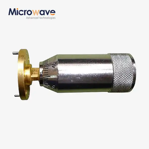
Impedance Matching and Tuning Systems
Research laboratories and industrial microwave heating systems employ these junctions with adjustable sliding shorts on the side arm to create series stub tuners. This configuration allows engineers to dynamically cancel reactive mismatches in transmission lines, protecting sensitive sources such as magnetrons or klystrons from reflected power that could reduce efficiency or cause damage. The tuning range exceeds what coaxial stub tuners can achieve while maintaining the power handling necessary for kilowatt-class generators. Testing facilities rely on this capability when characterizing antenna prototypes or optimizing industrial plasma systems.
The component's role continues expanding as 5G millimeter-wave infrastructure develops and next-generation satellite constellations deploy, with E-Plane Tee applications also increasing in these advanced RF and microwave systems. Procurement teams should consider future scalability when establishing supplier relationships, prioritizing manufacturers with demonstrated capability across multiple frequency bands and customization expertise for emerging applications.
Procurement Guide: How to Source and Purchase E-Plane Tees Efficiently?
Sourcing high-reliability waveguide components requires careful evaluation of supplier capabilities, quality certifications, and technical specifications to ensure components meet both immediate needs and long-term reliability requirements.
Identifying Qualified Suppliers and Manufacturers
Reputable manufacturers maintain comprehensive testing capabilities and quality management systems certified to ISO 9001 standards, with many defense-focused suppliers also holding AS9100 aerospace certifications. When evaluating potential E-Plane Tee suppliers, request evidence of Vector Network Analyzer (VNA) testing across the full specified frequency range, confirming that S-parameter measurements document VSWR, insertion loss, and phase balance within acceptable tolerances. Advanced Microwave Technologies Co., Ltd. exemplifies this commitment with measurement capabilities extending to 110 GHz and ISO 9001:2008 certification, ensuring traceability and consistent quality control throughout production.

Technical Specification Verification
Datasheets should clearly identify the operating frequency band, flange type (UG-style designation), VSWR specifications, insertion loss, and power handling limits. Cross-reference the waveguide size designation (WR-number) against standard tables to confirm compatibility with existing system components. Phase balance specifications become critical for radar and array applications—premium units maintain phase difference within ±2 degrees of the nominal 180-degree relationship across the full bandwidth. Request test data for actual production units rather than relying solely on typical performance curves, particularly for custom or modified designs.
Balancing Cost, Performance, and Lead Times
Standard catalog items from established manufacturers typically ship within two to six weeks, while custom designs requiring internal matching structures or special plating may extend to 10-12 weeks. Bulk purchasing often yields 15-25% cost reductions compared to single-unit pricing, making consolidated procurement across multiple projects financially advantageous. However, the lowest-cost option may compromise performance; a component with poor VSWR requires additional matching networks downstream, ultimately increasing system cost and complexity. Evaluate total cost of ownership by considering performance margins, reliability history, and technical support availability alongside unit price.
Quality Assurance and Acceptance Testing
Establish clear acceptance criteria before placing orders, specifying measurement methods and performance thresholds. Many procurement contracts include factory acceptance testing (FAT) where the supplier demonstrates compliance with specifications using calibrated test equipment before shipment. Coordinate dimensional inspection requirements, particularly for flange flatness and internal waveguide dimensions, using coordinate measuring machines (CMM) to verify conformance to MIL-STD specifications. Plating thickness verification through X-ray fluorescence (XRF) testing prevents adhesion failures that cause passive intermodulation problems in high-power applications.
Building relationships with technically capable suppliers who understand application requirements for E-Plane Tee streamlines future procurement cycles and enables collaborative problem-solving when system integration challenges arise.
Conclusion
The Series Tee delivers unmatched performance for applications requiring precise phase-controlled signal division, combining robust construction with the inherent 180-degree phase relationship that simplifies system design. Understanding the fundamental operating principles, recognizing the distinctive advantages compared to alternative components, and implementing rigorous procurement practices ensures your organization sources components that meet both immediate performance requirements and long-term reliability expectations. As microwave systems advance toward higher frequencies and greater complexity, the role of these passive components in enabling next-generation radar, satellite, and telecommunications infrastructure continues expanding. Strategic supplier relationships, thorough technical evaluation, and commitment to quality assurance position procurement teams to capitalize on these technological developments while maintaining the rigorous standards mission-critical applications demand.
FAQ
1. What distinguishes an E-Plane Tee from an H-Plane Tee in practical applications?
The fundamental difference lies in output phase relationship: the E-plane variant produces signals 180 degrees out of phase at collinear ports, while the H-plane version generates in-phase outputs. This determines application suitability—radar difference channels require E-Plane types for target tracking, whereas power combiners often use H-Plane configurations. The E-arm connects to the broad wall of the waveguide, distinguishing it structurally from the H-arm's narrow wall connection.
2. Why do basic designs exhibit poor VSWR performance?
The abrupt junction creates electromagnetic discontinuities acting as reactive elements—inductance or capacitance—that reflect significant signal energy. Without internal matching structures such as inductive posts or capacitive irises, VSWR values may exceed 2:1. Manufacturers compensate through careful tuning during design, achieving VSWR below 1.2:1 across specified bandwidths in production units.
3. Can these components function as power combiners?
Yes, but strict phase conditions apply. Signals entering collinear ports must arrive 180 degrees out of phase to sum constructively at the E-port; in-phase signals cancel out. This characteristic makes them suitable for balanced amplifier outputs and push-pull configurations where anti-phase signals naturally occur.
Partner with ADM for Premium E-Plane Tee Solutions
Advanced Microwave Technologies Co., Ltd stands ready to support your high-frequency signal distribution requirements with precision-engineered waveguide components backed by over 20 years of manufacturing expertise. Our E-Plane Tee solutions serve defense contractors, satellite integrators, and telecommunications providers demanding uncompromising quality and performance. With ISO 9001:2008 certification, RoHS compliance, and testing capabilities to 110 GHz, we deliver components that meet the most stringent specifications for mission-critical systems. Whether you need standard catalog items or custom-designed solutions tailored to unique application requirements, our technical team collaborates closely with procurement engineers to optimize performance, ensure compatibility, and accelerate project timelines. Contact craig@admicrowave.com today to discuss your specific requirements with our applications engineering team. As a trusted E-Plane Tee manufacturer with global logistics support, we provide competitive pricing, rapid prototyping services, and the quality documentation your supply chain demands.
References
1. Pozar, D.M. (2012). Microwave Engineering, 4th Edition. Hoboken: John Wiley & Sons, Inc.
2. Collin, R.E. (2001). Foundations for Microwave Engineering, 2nd Edition. New York: IEEE Press.
3. Chatterjee, R. (1988). Elements of Microwave Engineering. Chichester: Ellis Horwood Limited.
4. Montgomery, C.G., Dicke, R.H., and Purcell, E.M. (1948). Principles of Microwave Circuits. New York: McGraw-Hill Book Company.
5. Saad, T.S. (1971). Microwave Engineers' Handbook, Volume 1. Dedham: Artech House.
6. Ragan, G.L. (1948). Microwave Transmission Circuits. MIT Radiation Laboratory Series, Volume 9. New York: McGraw-Hill Book Company.