How Does a Waveguide Variable Attenuator Work?
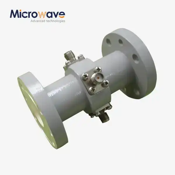
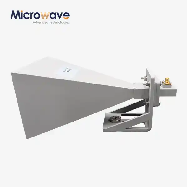
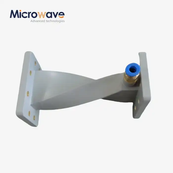
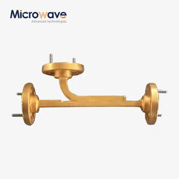
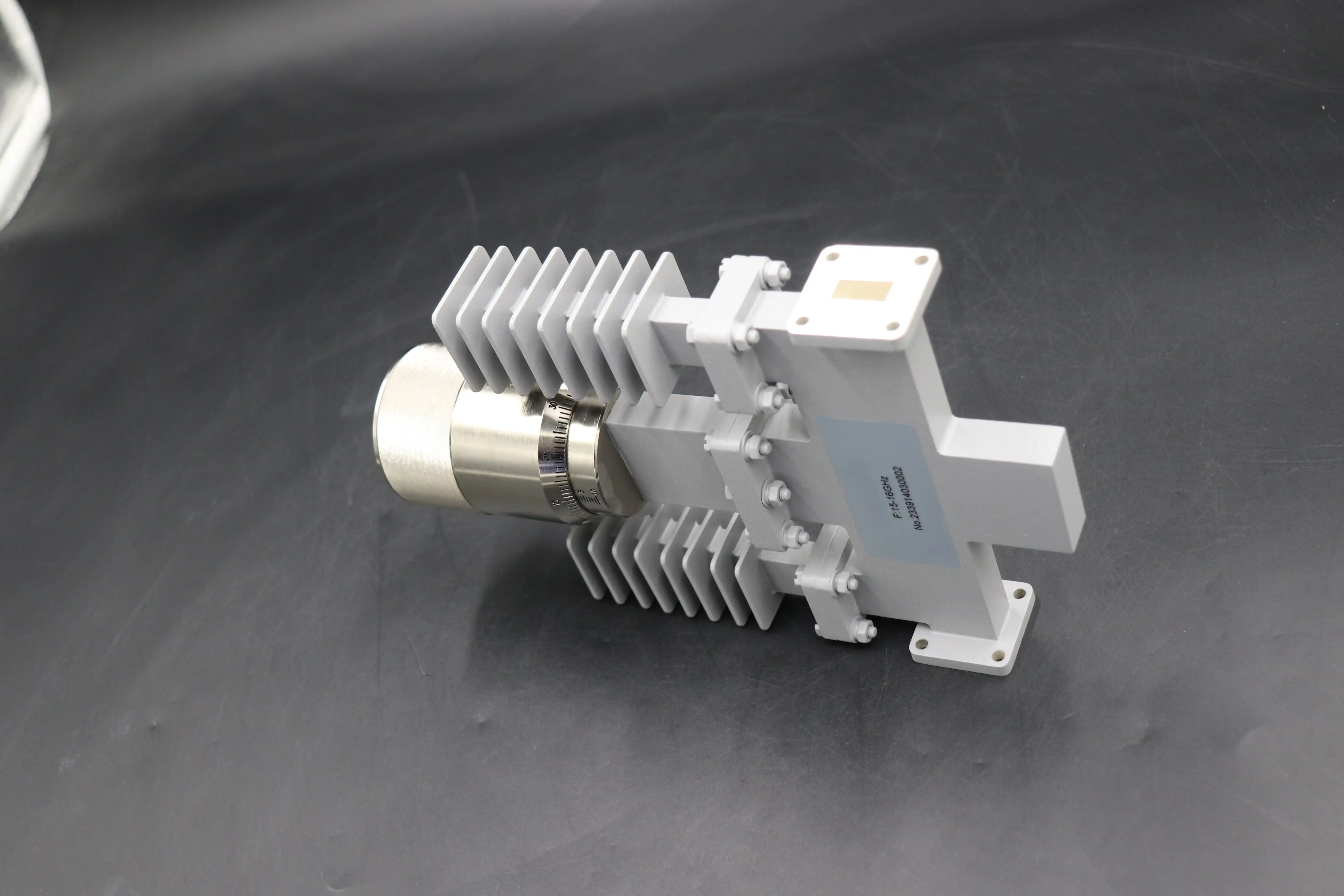
A waveguide variable attenuator is a precision microwave component that controls the amplitude of an electromagnetic signal traveling through a waveguide transmission line. By inserting a resistive dielectric vane into the waveguide's electric field, it introduces adjustable insertion loss — typically from 0 dB up to 30 dB or beyond — without interrupting the signal path. As the vane moves deeper into the field, more energy is absorbed. This mechanism keeps VSWR low, preserves signal integrity, and makes these devices indispensable for radar calibration, receiver testing, and high-frequency measurement applications across X-band through W-band systems.
Understanding Waveguide Variable Attenuators: Principles and Operation
How Attenuation Is Physically Achieved
A resistive vane, which is a thin card covered with a lossy dielectric material, is usually put inside the waveguide cavity. This is the most popular form. When it is lined up parallel to the electric field lines, it takes in energy at a rate equal to the depth of its entry. The reduction level is always changing whether the vane is rotated or moved. This method absorbs energy and sends it out as heat instead of sending it back toward the source, which keeps parts further upstream safe.
Manual vs. Motorized Operation
A calibrated drum scale or a micrometer-driven device is used in manual types. Direct-reading drums show attenuation in decibels (dB), while micrometer types have better mechanical precision (often as low as 0.01 dB), but they need a calibration chart to go from dial position to dB value. Motorized versions connect stepper motors to digital interfaces like GPIB, USB, or Ethernet. This lets attenuation sweeps happen automatically in test environments without any help from a person.
Key Technical Parameters to Know
Before writing a purchase order, procurement engineers should pay close attention to these electrical terms regarding the waveguide variable attenuator:
- Frequency range: WR-90 covers the X-band (8.2–12.4 GHz), WR-28 covers the Ka-band (26.5–40 GHz), and WR-10 covers the W-band (75–110 GHz).
- Attenuation range and accuracy: Rotary vane systems can usually achieve a range of 0 to 60 dB and an accuracy of within ±0.1 dB, or 2% of the reading.
- Insertion loss at 0 dB setting: High-quality units stay below 0.5 dB residual loss, which protects the link budget as a whole.
- VSWR: A value below 1.15:1 across the whole range means that there is less reflected power, which could hurt a source amplifier.
By knowing these factors, buyers can write specifications that fit their system design right from the start, which saves them the cost of having to re-qualify later.
Applications and Benefits in Modern B2B Procurement Scenarios
Where These Devices Are Deployed
Defense radar systems, 5G base station testing rooms, satellite ground station commissioning benches, and research-grade vector network analyzer (VNA) sets all use waveguide variable attenuators. In pulsed radar, the dynamic range of the receiver is set by simulating changing target-return amplitudes. In 5G test cells, radio units are put through stress tests that look like link loss situations before they are used in real life.
Core Performance Benefits
In a number of ways, these gadgets provide measurable value. Here are the main benefits that should be emphasized when making buying decisions:
- High power handling: These attenuators can handle kilowatts of peak power, which is more than what coaxial alternatives can handle for pulsed radar. This is because the waveguide has an air dielectric and metal walls that let heat escape.
- Low signal distortion: The absorptive vane mechanism keeps intermodulation and harmonic generation products very low, which maintains the accuracy of the measurements.
- Environmental durability: Housings made to MIL-DTL-3933 standards can handle high and low temperatures, shaking, and humidity, which is important for installations in the air or on ships.
Defense original equipment manufacturers (OEMs) and satellite integrators need these benefits because they can't have parts fail in the field.
Troubleshooting Common Issues
Over time, insertion loss is usually a sign of rust or contamination on the resonant vane surface. Every so often, VNA sweeps find this early. When mechanical drives are used in damp places, they should be checked for thread seizure. Most of the time, frequency drift in calibration is caused by worn flange contact surfaces, not the vane itself.
Waveguide Variable Attenuator vs. Alternatives: Making Informed Choices
Fixed Attenuators and Their Limitations
With a fixed attenuator, the dB number stays the same. This makes them the best choice when the system loss budget is set and won't change. They are less expensive and take up less room. However, they can't be adjusted, so they can't be used in any situation where dynamic range control or iterative calibration is needed.
Coaxial and PIN Diode Models
Coaxial waveguide variable attenuators work well at lower frequencies and in small packages, but at millimeter-wave frequencies, their center conductor makes it harder to handle peak power and raises insertion loss. PIN diode attenuators switch electronically at microsecond speeds, which is good for fast-switching test situations. However, they cause nonlinear behavior at high power and make the DC bias circuits more complicated.
Manual vs. Motorized: Which to Choose
A manual unit works well in labs where changes are made infrequently, and there is an operator present. It is best to buy an automatic unit for automated test equipment (ATE) racks, where scripts change the amount of attenuation hundreds of times a day. The extra cost of a powered machine is quickly recouped by less time spent by operators and better consistency across test floors for production.
Selecting and Procuring Waveguide Variable Attenuators: A B2B Buying Guide
Defining Your Specification Baseline
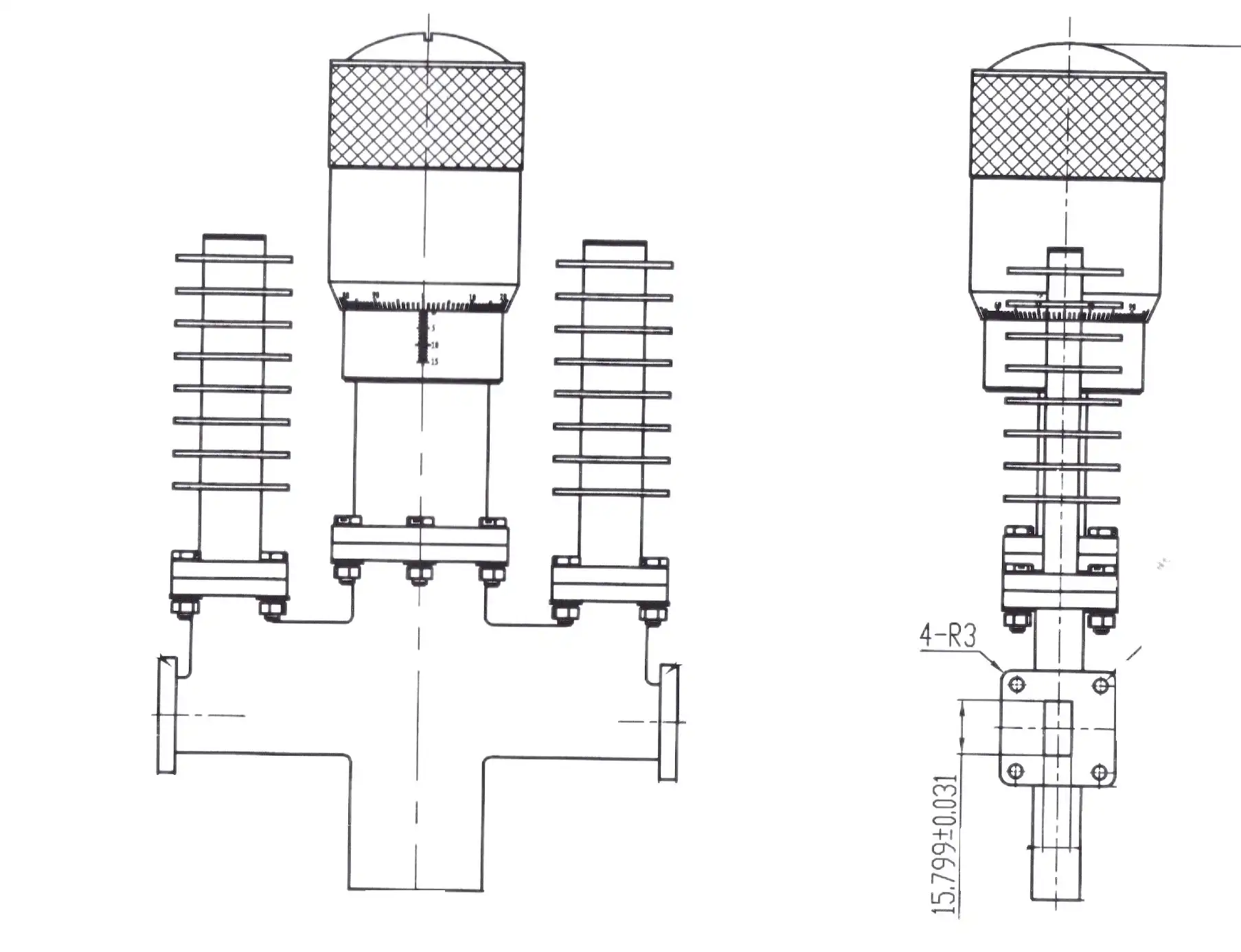
Starting with four important factors that can't be changed are the working frequency band, the needed attenuation range, the highest average and peak power levels, and the type of control interface. Make sure that the waveguide flange standard (UG, CPR, or custom) fits the gear you already have for the assembly. If it doesn't, adapter losses could throw off the calibration results.
Evaluating Suppliers on Quality and Documentation
You can learn a lot about a supplier's production method from how willing they are to give you calibration certificates, test data sheets, and material traceability documents. Defense and satellite purchases must have at least one ISO 9001:2015 approval. RoHS compliance is important for programs that need to sell environmentally friendly goods. Before placing a large order, ask for example data to check for insertion loss and VSWR across the whole frequency range.
Procurement Logistics and Lead Times
Most respected producers have lead times of four to eight weeks for standard waveguide variable attenuators in typical bands. This is made longer with custom flanges or attenuation ranges that aren't standard. Ask if there are any prototypes available if the design proof part of your program is still going on. For production programs, blanket purchase agreements and bulk order pricing can cut costs per unit by a large amount.
Case Studies and Practical Insights: Verifying Performance and Value
5G Test Lab Application
A company that makes telecom equipment put motorized waveguide variable attenuators into their 5G mmWave radio test benches that work at 28 GHz (WR-28 band). By automating attenuation sweeps from 0 to 40 dB, they cut the time needed to calibrate each unit by about 60% compared to manual adjustment. During the test sequence, they kept insertion loss below 0.4 dB and VSWR below 1.12:1.
Radar System Calibration
For receiver sensitivity calibration, defense radar programs often use rotary vane attenuators. The air-dielectric waveguide system is the only one that works for pulsed radar because its peak power levels can hit several kilowatts. One well-known method involves using a precise micrometer to drive an attenuator at the X-band to bring known signal levels into the receiver front end. This checks the minimum detectable signal thresholds against the design specifications.
Emerging Trends in Precision Control
More people want W-band (75–110 GHz) attenuators because working frequencies are going up for things like automotive radar, imaging systems, and 6G study projects. Manufacturers that keep testing equipment up to 110 GHz in good shape, like ADM's 24-meter microwave lab, can check performance at frequencies where figuring out what a part is made of is really hard.
Conclusion
A waveguide variable attenuator lets engineers precisely and repeatedly change the intensity of an RF signal without changing the frequency or causing major distortion. Procurement professionals can write accurate specifications and choose the right part the first time they do it if they understand the attenuation mechanism, key electrical parameters, and differences between manual, motorized, and other technologies. It is possible to see and measure the difference in performance between a well-specified waveguide attenuator and a coaxial substitute in research labs, 5G test benches, and defense radar. Because ADM can test and make a lot of different products, they are a reliable buying partner for projects where the quality of the parts directly affects how well the system works.
FAQ
What frequency bands do waveguide variable attenuators typically cover?
Standard designs connect to well-known waveguide bands, such as the L-band, the X-band (WR-90), the Ka-band (WR-28), and the W-band (WR-10). One unit fully covers its own band, so you choose the waveguide size that works with the frequency of your system.
How do I verify calibration authenticity?
Ask for a testing certificate that can be linked to a national standards organization like NIST. The certificate should have the measurement error statement and the observed attenuation values at a number of frequency points and adjustment points.
Can these attenuators handle pulsed radar power levels?
Yes. The metal body and air-dielectric design let a waveguide variable attenuator handle peak power in the kilowatt range. It's important to check both numbers for rapid uses because the average power level depends on how well the resistive vane can get rid of heat.
Are motorized models compatible with standard ATE interfaces?
Motorized units with GPIB, USB, or Ethernet interfaces work with standard ATE software and allow for script-controlled attenuation sweeps.
What maintenance schedule is appropriate?
Check the VNA insertion loss every six months when the lab is being used normally. When units are out in the field in tough conditions, the mechanical drives and flange contact surfaces should be checked every three months.
Partner with ADM for Your Waveguide Variable Attenuator Requirements
Advanced Microwave Technologies Co., Ltd. (ADM) has been making waveguide variable attenuators for more than 20 years and brings that experience to every order. Our products are certified by ISO 9001:2015 and meet RoHS requirements. You can also get full calibration documentation for them. We offer OEM customization, quick turnaround times for prototypes, and volume discounts for production programs. Our tech team is ready to help you whether you need a normal X-band unit or a W-band configuration that is made just for you. To get a price right away, email us at craig@admicrowave.com.
References
1. Pozar, D. M. Microwave Engineering, 4th ed. Wiley, 2011.
2. Collin, R. E. Foundations for Microwave Engineering, 2nd ed. IEEE Press / Wiley-Interscience, 2001.
3. Montgomery, C. G., Dicke, R. H., & Purcell, E. M. Principles of Microwave Circuits. MIT Radiation Laboratory Series. McGraw-Hill, 1948.
4. IEEE Standard for Waveguide and Waveguide Component Measurements, IEEE Std 1785-2012. IEEE, 2012.
5. Ramo, S., Whinnery, J. R., & Van Duzer, T. Fields and Waves in Communication Electronics, 3rd ed. Wiley, 1994.
6. MIL-DTL-3933: Detail Specification for Attenuators, Fixed and Variable, Radio Frequency. U.S. Department of Defense, 2005.