Horn Lens Antenna for Microwave Systems: Performance Guide
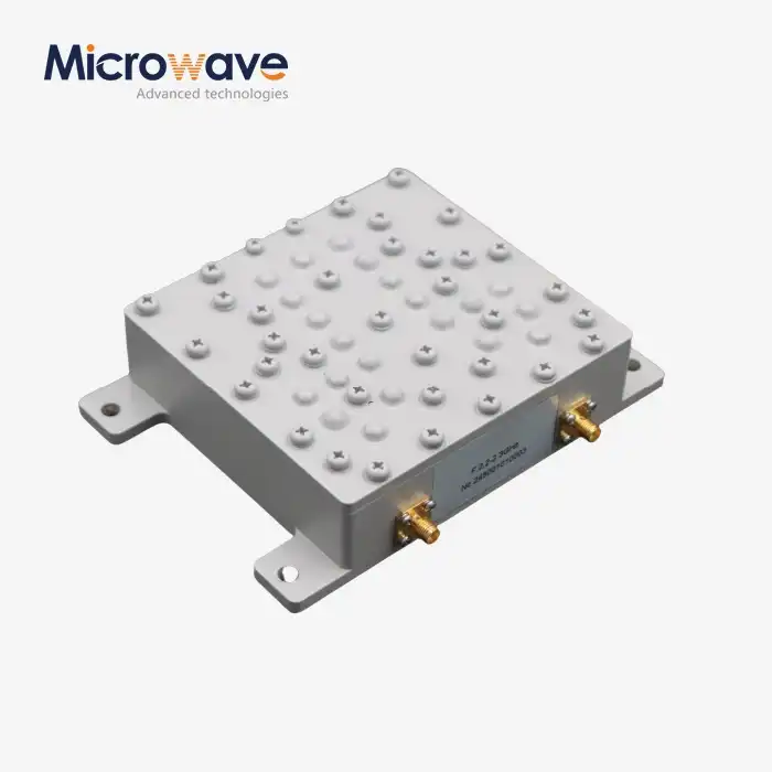
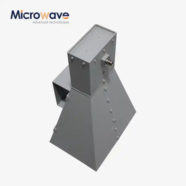
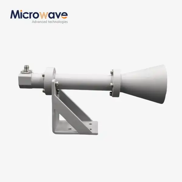
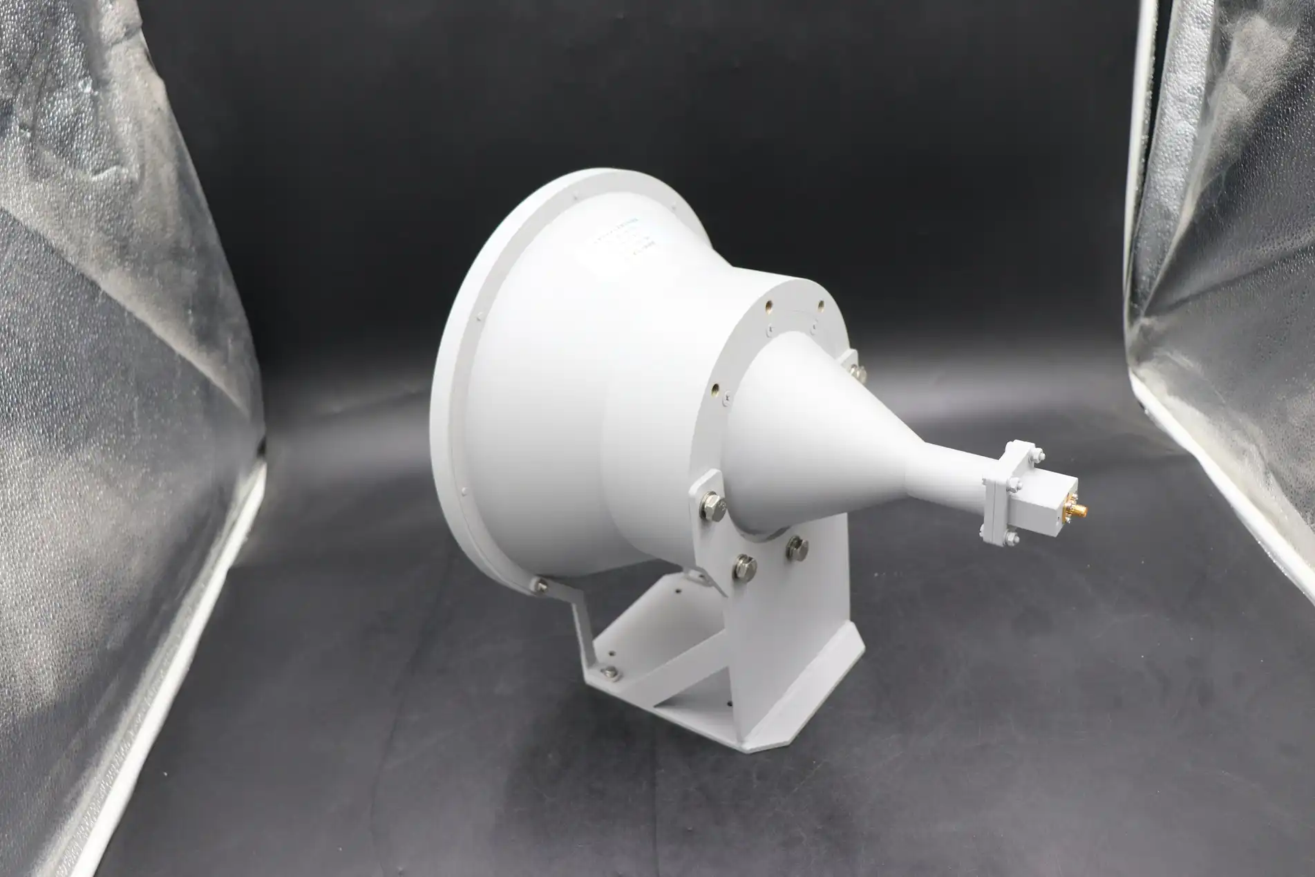
Horn lens antennas represent a sophisticated fusion of traditional horn architecture and precision dielectric lens technology, delivering superior beam control and enhanced directivity in mission-critical microwave applications. By integrating carefully engineered lens elements into the horn aperture, these antennas achieve narrower beamwidths and higher gain compared to standard horn designs, making them invaluable for radar systems, satellite ground stations, and next-generation wireless infrastructure where signal accuracy determines operational success.
Understanding Horn Lens Antennas: Fundamentals and Performance
What Sets Horn Lens Antennas Apart?
We've seen that horn lens antennas have both the strong mechanical structure of standard horn radiators and the precise beam-shaping ability of dielectric lenses. A big problem in RF engineering is getting high directivity without making the device too big. This combined method solves that problem. Electromagnetic waves coming from the horn neck are focused into a narrow beam by the dielectric lens, which is usually made of low-loss materials such as PTFE, polystyrene, or special ceramics. The lens element improves phase correction across the aperture, which leads to cleaner radiation patterns and lower side lobe levels compared to traditional horn antennas that only use flared geometry for directionality.
Core Design Parameters That Drive Performance
The effectiveness of these antennas depends on a number of design factors that work together. How well the beam is collimated is directly related to the lens shape, which includes the curve radius and thickness profile. Choosing the right material has an impact on both insertion loss and frequency response. Materials with lower dielectric constants tend to have wider bandwidths, but they need to be bigger. Our engineering team at Advanced Microwave Technologies Co., Ltd. has been optimizing these parameters for over 20 years in our state-of-the-art 24m Microwave Darkroom. This is where we can accurately measure antenna behaviour from 0.5 to 110 GHz using our Antenna Plane Near and Far Field Measuring Recombination Chamber.
Frequency Coverage and Application Domains
Horn lens antenna designs work well in a lot of different frequency ranges, meeting a wide range of business needs. They power weather radar and air traffic control systems that need to be able to tell the difference between very close targets in the X-band (8–12 GHz). Ku-band versions (12–18 GHz) work with satellite phones and VSAT networks. Ka-band versions (26.5–40 GHz) let high-speed 5G backhaul and millimeter-wave point-to-point links happen. The antennas' broad capabilities make them very appealing for defense uses, where being able to change frequencies quickly and having a low chance of being intercepted are important. Our factories can make products that work with both old and new wireless standards because they can handle special frequency specs.
Performance Advantages in B2B Procurement Context
When purchase engineers compare radio technologies, horn lens designs are different from other options in a number of ways:
- Compact form factor: Compared to parabolic reflectors of the same performance, it achieves high gain in smaller volumes, which reduces the installation footprint and wind loading on tower structures.
- Predictable radiation characteristics: Stable beam patterns across working bandwidth with little phase distortion, making system integration easier for OEM makers making complicated RF parts.
- Environmental resilience: Solid dielectric construction is better at handling temperature changes, water getting in, and mechanical vibrations than aperture-array designs, meeting the high standards for reliability that defense contractors demand.
- Manufacturing scalability: It can be used for both small-batch prototyping in research institutions and large-scale production for telecom infrastructure deployments. ISO 9001:2015-certified processes ensure consistent quality.
These qualities are exactly what satellite systems integrators and aircraft OEMs want. They need parts that give them measurable performance benefits in harsh operating circumstances.
Performance Optimization of Horn Lens Antennas in Microwave Systems
Addressing Beamwidth and Side Lobe Challenges
To get the most out of a horn lens antenna, you must first understand its limits. Beamwidth limits come from the relationship between aperture size and wavelength; even with lens correction, directivity is limited by physical dimensions. Side lobe levels, which are brought on by aperture edge diffraction and flaws in the lens surface, can lower signal-to-interference ratios in areas with a lot of interference. Precision CNC machining of lens elements and electromagnetic simulation-driven shape improvement have helped us improve the way we make things so that these effects are lessened. Our quality control procedures check that side lobe suppression ratios are higher than -25 dB across certain frequency ranges. This makes sure that we meet strict regulatory masks.
Alignment Precision and Calibration Requirements
Installation precision has a big effect on how well the antenna actually works. A shift of just one degree can lower on-axis gain by 1 to 3 dB, depending on beamwidth, and add cross-polarization components that hurt link margins. When we send out antennas from Advanced Microwave Technologies Co., Ltd., we include detailed alignment fixtures and optical boresighting tools. These help users get sub-0.5-degree pointing precision. Our approved labs came up with calibration methods that take into account lens dielectric changes that depend on temperature as well as mechanical settling over the first few operational cycles. This keeps link budgets stable over the life of the product.
Material Innovation and Beam Shaping Advances
New developments in low-loss dielectrics have made horn lens antennas more useful. Temperature-stable composite materials now keep their permittivity constant from -40°C to +85°C. This gets rid of the yearly gain changes that were a problem with older designs. We were also the first to use gradient-index lens profiles to fix higher-order aberrations and get above 85% near-theoretical aperture efficiency. A satellite ground station user in the Midwest recently reported a gain improvement of 2.3 dB after switching to our optimized Ka-band horn lens design. This means that during rain fade events, there is measurably higher throughput. Through better pattern control, another rollout in 5G millimeter-wave infrastructure showed a 15% drop in inter-sector crosstalk.
These tests done in the real world show how useful precise engineering is in harsh microwave system settings where every tenth of a decibel counts.
Comparing Horn Lens Antennas to Alternative Microwave Antennas for Procurement Decisions
Evaluating Technology Trade-Offs
Choosing the best antenna technology means weighing a lot of different factors. Parabolic reflectors have a higher peak gain, but they are heavy and lose signal when the feed gets blocked. Patch antenna arrays let you move an electrical beam, but they are more complicated because they have phase shifter networks and higher insertion losses. Phased arrays are very flexible, but they need complex control systems and cooling infrastructure, which raises the costs of both capital and running the system. Horn lens antennas are a good compromise because they offer 20–30 dBi gain in packages that weigh less than 5 kg and don't have any active parts that need to be powered up or maintained.
The comparison below shows the main differences that B2B buying experts should know about:
| Antenna Type | Typical Gain | Bandwidth | Complexity | Ideal Applications |
|---|---|---|---|---|
| Horn Lens | 20-30 dBi | 10-30% | Low | Radar feeds and satellite terminals |
| Parabolic | 25-50 dBi | 5-20% | Medium | Wireless links that go a long way |
| Patch Array | 15-25 dBi | 2-10% | Medium | Mobile platforms and embedded systems |
| Phased Array | 20-40 dBi | 20-40% | High | Defence EW and flexible communications |
Application-Specific Selection Framework
Horn lens antennas can handle a lot of power and keep their phase stable, which helps defense radar systems track targets accurately even in crowded areas. Installations that use satellite communication like how well they work in a wide range of temperatures and how well they don't build up static electricity when it rains. Research labs like how easy it is to calibrate the devices and how they can make their own frequency variations for experiments. OEM makers that include RF modules like how simple the mechanical parts are and how the electrical characteristics can be repeated, which makes system validation easier.
Knowing these application-specific goals helps buying teams match technical specifications with practical needs. This way, they can avoid over-engineered solutions that cost more than they're worth and don't deliver the benefits that were promised.
Procurement Guide: Buying Horn Lens Antennas for Global B2B Clients
Pricing Models and Customization Options
Prices for horn lens antennas depend on how hard they are to build, what frequencies they work with, and how many are made. Prices for standard catalogue models in common bands run from $800 to $3,500 per unit, based on the gain and bandwidth requirements. Custom designs that use special materials, meet specific environmental standards, or meet specific interaction needs cost 40 to 70 percent more than standard designs, but they work better in certain situations. Orders over 50 units qualify for volume discounts, and qualified OEM partners who sign long-term supply agreements can get price cuts of 15 to 25 percent.
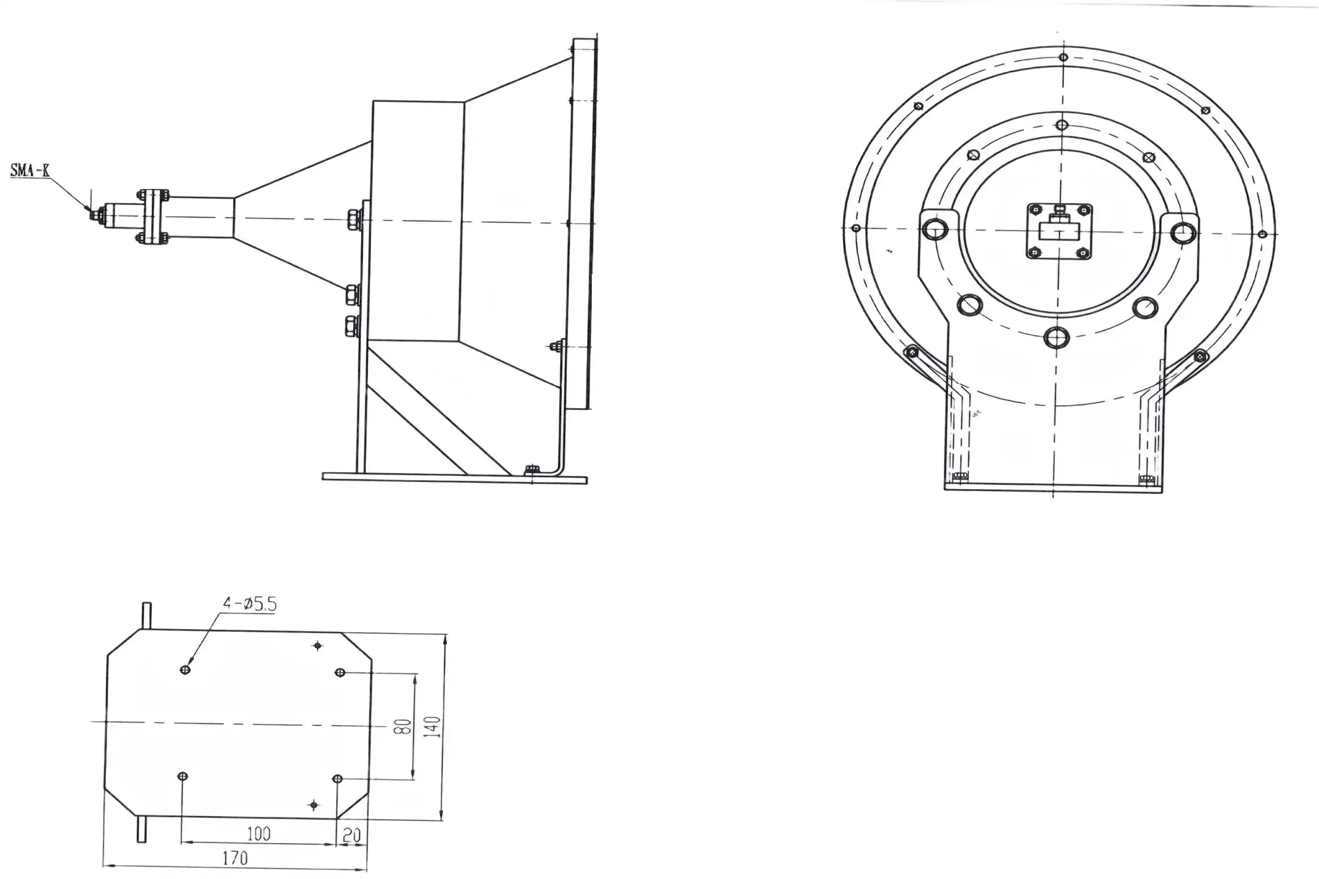
At Advanced Microwave Technologies Co., Ltd, we offer flexible engagement models. Prototyping services offer quick turnaround—often within three weeks—for initial design validation, which lets engineering teams check how well the design works before committing to large-scale production. Our OEM services allow for full customization, from changing the frequency and adding a radome to specifying connectors and mounting options.
Evaluating Supplier Capabilities
Successful procurement outcomes depend on thorough supplier assessment. Critical evaluation criteria include:
- Quality certifications: Make sure the company meets environmental standards like RoHS and ISO 9001:2015. Our sites have ISO 14001:2015 and ISO 45001:2018 standards, which show that we care about both product quality and environmental responsibility.
- Measurement capabilities: Make sure that the providers have anechoic chambers that are big enough for the frequency range you need. Our 24m Microwave Darkroom can handle measurements in the far field up to 110 GHz, which guarantees accurate performance characterisation.
- Technical support depth: Look at the technical tools that are available to help with application advice, installation, and fixing problems. For over 20 years, our team has been deploying systems in the field for use in aviation, aerospace, shipboard systems, and unmanned aerial vehicles (UAVs).
- Supply chain transparency: Look at how easy it is to track down parts and how well the manufacturing process is documented, especially for defence and military projects that need to know the full history of materials.
Initiating Supplier Engagement
Begin procurement discussions by clearly defining technical requirements: frequency range, gain targets, bandwidth needs, environmental conditions, and mechanical interface specifications. Ask for detailed datasheets with measured radiation patterns, VSWR curves, and data on how the device works at different temperatures. Suppliers who are qualified should show modelling results that back up design claims and offer sample units so that other people can try them. Establishing clear communication channels early on, including direct access to tech staff, speeds up the process of fixing problems during the merging stages.
Installation, Calibration, and Maintenance of Horn Lens Antennas
Site Selection and Mounting Techniques
Proper installation begins with horn lens antenna site evaluation. Check the line-of-sight to make sure that Fresnel zone obstructions don't hurt the signal quality. Place antennas on stable structures that don't let too much shaking from equipment or wind load get through. We suggest stiff mounting brackets that have adjustment options in both the azimuth and elevation planes. This makes alignment easier without having to take the antenna off. Weatherproofing methods, like installing a radome and closing connectors, keep water out of the lens surfaces and feed interfaces, which lowers the electrical performance.
Alignment Procedures and Calibration Steps
Methodical balance is needed to get the best results. First, use a compass to get a rough idea of where the target is. Then, use received signal strength signs or spectrum analyzer readings to get more accurate. Optical boresights speed up this process, especially for designs with narrow beams that need to be very precise with angles. Once the machine is in the right place mechanically, you can do electrical calibration by checking the return loss and radiation patterns. Record initial measurements so that you can use them again in the future. This will help you spot patterns of degradation as the system is used. Our technical support team offers detailed alignment protocols that are tailored to specific antenna models, reducing installation time and ensuring specification compliance.
Preventive Maintenance Best Practices
Regular checks make horn lens antenna systems last longer. Visual checks done every three months find any physical damage, connector corrosion, or radome degradation that needs fixing. Every year, pattern readings make sure that the electrical performance stays stable, finding small changes in performance before they hurt the link margins. Clean lens surfaces with appropriate solvents, avoiding abrasive materials that can damage dielectric coatings. In seaside or industrial areas, inspections should be done more often to account for faster rusting. Our after-sales support includes maintenance guidelines tailored to deployment environments as well as quick access to spare parts to keep downtime to a minimum during unplanned replacements.
Conclusion
Horn lens antennas provide a powerful combination of high gain, small size, and dependable performance that is ideal for B2B microwave system deployments. Their elegant design, which combines the strength of the horn with the accuracy of the lens, solves real-world problems that procurement engineers face, such as the need for space-constrained satellite stations and ruggedised radar feeds that can handle harsh weather conditions. The technology's track record in satellite communications, defence, military, and industry use shows how flexible it is in a way that few other options can match. At Advanced Microwave Technologies Co., Ltd., our advanced measurement tools up to 110 GHz, ISO-certified production processes, and full expert support turn these performance advantages into real operational benefits. Our knowledge will make sure that your antenna solution gives you measurable competitive advantages whether you're upgrading existing infrastructure or creating systems for the next generation.
FAQ
1. What distinguishes horn lens antennas from standard horn designs?
When compared to conventional horn antennas that only use flared geometry, horn lens antennas have dielectric lens elements that provide better phase correction across the aperture. This allows for narrower beamwidths and higher gain in smaller packages.
2. Which frequency ranges work best for 5G infrastructure applications?
Millimeter-wave bands, such as Ka-band (26.5-40 GHz), work well for 5G fronthaul and backup lines. In these frequency bands, horn lens antenna designs provide the focus needed for point-to-point links while keeping the bandwidth high enough for gigabit data rates.
3. Can horn lens antennas be customized for defense applications?
Absolutely. To meet the needs of the defense sector, we often change the frequency coverage, polarization setups, power handling ability, and environmental ratings. Our engineering team works directly with defence contractors to make sure that all military standards and security protocols are followed.
Partner with ADM for Your Microwave Antenna Needs
Every horn lens antenna project is handled by Advanced Microwave Technologies Co., Ltd with unmatched expertise, backed by ISO 9001:2015, ISO 14001:2015, and ISO 45001:2018 certifications ensuring quality, environmental responsibility, and workplace safety. Our global supply chain, refined over 20 years, delivers components meeting the strictest reliability standards for satellite communications, defense, aerospace, and navigation applications. Whether you need catalogue products or fully customized designs, our experienced technical team provides comprehensive support from initial specification through installation and maintenance. As a trusted horn lens antenna manufacturer, we offer competitive pricing, rapid prototyping, and volume production capabilities that scale with your requirements. Contact craig@admicrowave.com today to discuss your specific application challenges and receive detailed technical recommendations tailored to your operational environment.
References
1. Balanis, C. A. (2016). Antenna Theory: Analysis and Design (4th ed.). Wiley.
2. Goldsmith, P. F. (1998). Quasioptical Systems: Gaussian Beam Quasioptical Propagation and Applications. IEEE Press.
3. Milligan, T. A. (2005). Modern Antenna Design (2nd ed.). Wiley-IEEE Press.
4. Rao, S. (2010). Lens Antennas for Wireless Communications. IEEE Microwave Magazine, 11(6), 62-72.
5. Silver, S. (1984). Microwave Antenna Theory and Design. Peter Peregrinus Ltd.
6. Stutzman, W. L., & Thiele, G. A. (2012). Antenna Theory and Design (3rd ed.). Wiley.