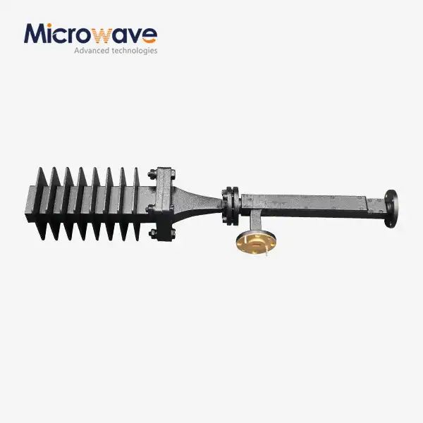
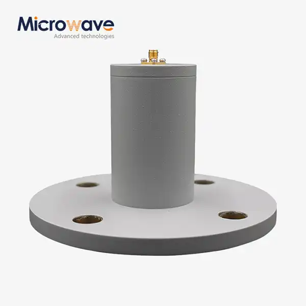
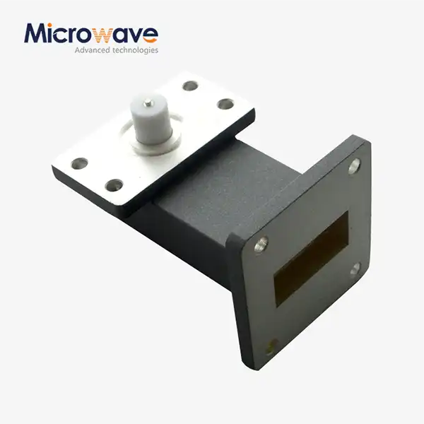
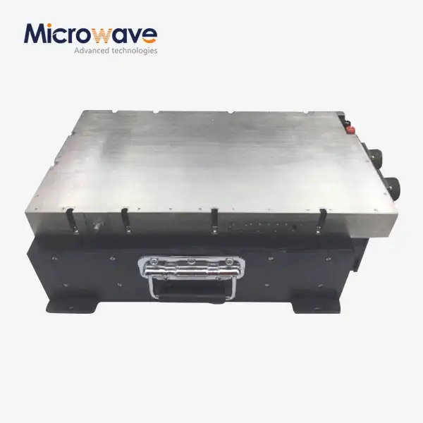
High Power Waveguide Isolators Selection Guide for Engineers
Selecting the right high power waveguide isolators requires understanding how these passive, non-reciprocal devices protect sensitive RF sources from damaging reflected energy. These components transmit signals in one direction while absorbing reverse power, preventing equipment failures in radar, satellite, and industrial heating systems. Engineers must balance insertion loss, isolation performance, thermal management, and power handling capacity against application requirements and budget constraints to ensure reliable, long-term operation in mission-critical environments.
Understanding High Power Waveguide Isolators: Working Principles and Key Specifications
In RF transmission chains, high power waveguide isolators act as shields to protect expensive sources like magnetrons, klystrons, and solid-state power amplifiers from reflected energy caused by impedance mismatches. Engineers can choose devices that keep systems stable and avoid catastrophic breakdowns by understanding how they work on a basic level.
How Non-Reciprocal Transmission Works
These devices rely on ferromagnetic resonance in permanently magnetized ferrite. Radio frequency energy enters the waveguide via the forward port and passes through the ferrite structure nearly without loss. When signals flow backward into a phase-shifted magnetic field, the energy is converted into heat by an internal resistance load. This non-reciprocal phenomenon is caused by electromagnetic waves with circular polarization interacting with magnetic moments in the ferrite lattice that travel back and forth. The operating frequency band must match the waveguide housing's rectangular or circular cross-section. This improves field coupling and reduces device port reflections.
Critical Performance Parameters Engineers Must Evaluate
When operating properly, the isolator absorbs forward signal power (insertion loss). This loss is commonly 0.1–0.3 dB in excellent devices. Lower insertion loss reduces heat production and improves system efficiency. An isolation capability of above 20 dB indicates a device's ability to prevent reverse signals. Higher values protect sources better. The VSWR indicates impedance matching. Below 1.15:1 is great across bandwidth. Peak and average power handling parameters exist. Waveguide size and gas pressure to halt arcing determine peak power capacity. Average power handling depends on heat sink and cooling system efficiency.
Thermal Management and Material Selection
High-power waveguide isolators' key technological challenge is managing reverse energy heat. Ferrite materials must maintain magnetic properties below their Curie temperature. Magnetic ordering and isolation capabilities decline at this stage. Advanced designs employ liquid cooling channels or forced-air heat sinks with lithium or nickel ferrite Curie temperatures exceeding 300°C. When reflected power fluctuates abruptly, monitor the temperature because long-term overheating might permanently detune the device or break the ferrite elements. Engineers should ask manufacturers for thermal performance curves showing isolation and insertion loss throughout the device's temperature range.
Testing and Maintenance Best Practices
Reliable functioning throughout 10-year lifecycles requires preventative maintenance. To detect rust or clogs early, evaluate cooling system flow rates and entry temperatures every three months. Every six months, network analyzer sweep tests ensure appropriate insertion loss and isolation. Gradual decline may indicate internal ferrite breakdown or magnetic field weakening. Helium detection must be used annually to monitor pressurized systems for leaks since even tiny pressure losses may impair peak power handling and cause arcing. Tracking performance trends enables you to replace parts before they break down, which is particularly useful in military and satellite ground stations where downtime is expensive.
Comparing High Power Waveguide Isolators: Making the Right Choice for Your Application
To find the right isolator for your needs, you need to know the differences between device architectures and match performance characteristics to operational needs. Systematic comparison models that show the trade-offs between cost, performance, and environmental toughness are helpful for engineers.
High Power Versus Standard Power Devices
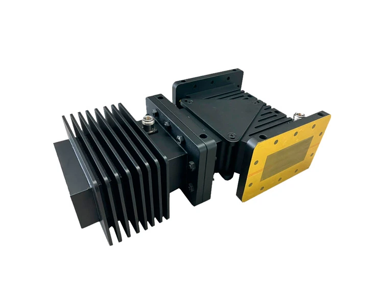
Standard milliwatt to low-watt waveguide isolators lack heat piping and ferrite volume for kilowatt transmissions. High power waveguide isolators include larger ferrite systems and specific cooling features to run constantly at power levels that would kill conventional devices. A 5 cm X-band isolator is different from a 20 cm high-power version with cooling flanges. This smaller size reduces survival. High-power devices can survive transmitter tuning, antenna icing, and transient load disconnections.
Isolators Versus Circulators in System Design
Ferrite-based isolators and circulators are non-reciprocal. Isolators use a two-port forward-reverse arrangement, whereas circulators sequentially transfer signals between three or more ports. Circulators are ideal for radar systems and other applications that need simultaneous transmission and reception over shared antennas. The antenna is powered, and received signals are sent to a detector port. When just forward transmission is necessary, isolators provide safety. They feature simpler mechanical designs and smaller insertion loss. System developers choose port-to-port signal routing depending on whether it contributes more than source safety.
Performance Criteria Across Leading Models
Diverse designs have significantly diverse bandwidths. Broadband models cover 40% of bandwidth but have greater insertion loss. However, narrowband devices with insertion loss < 0.15 dB are preferable for radar or communication frequencies. Commercial-grade devices can only function in a controlled lab, but ruggedized military-spec systems can endure shock, pressure, and temperature fluctuations under MIL-STD-202. Defense engineers should follow environmental test requirements and get test results showing that conditions were survived. Power handling rises with waveguide size/frequency. Larger WR-284 waveguide isolators can manage megawatt peak outputs at L-band, while millimeter-wave devices in the WR-10 waveguide can only handle kilowatts due to their heat and energy restrictions.
Cost Versus Performance Trade-Offs
If a project has a low budget, it may acquire the greatest pricing by ensuring the isolator meets application criteria. High reflected power is unusual on satellite ground station uplinks with steady loads. Moderate isolators may be utilized with natural convection cooling. Despite their higher cost, industrial RF heating systems with changeable load impedance need the finest isolation and thermal design. The purchase price, installation complexity, cooling infrastructure required, and maintenance frequency make up the total cost of ownership. Longer lifespans and reduced downtime make pricey technologies pay for themselves.
Procurement Guide: How to Buy High Power Waveguide Isolators Efficiently
To make sure that parts are delivered on time and meet strict quality standards, successful procurement combines accurate technical specifications with strategic evaluation of vendors. To make this process go more quickly, engineers use organized methods to find suppliers, compare quotes, and lower financial risk.
Identifying Qualified Manufacturers and Distributors
Reliable high-power waveguide isolator vendors have ISO 9001 certification, RoHS paperwork, and performance data to prove they can build the items. Perfect description for Advanced Microwave Technologies Co., Ltd. They have facilities that can measure up to 110 GHz and have made high-precision RF parts for over 20 years. Engineers should prioritize OEM design services that enable them to pick non-standard frequency bands, flange types, and cooling interfaces that fit existing system designs. Distributors may combine sources and stock locally, but they may not have the technical expertise to suit unique demands. Working directly with manufacturers is best for complex projects.
Understanding Pricing Dynamics and Lead Times
Waveguide size, frequency range, power level, and production quantity determine unit pricing. Standard X-band systems cost $800, whereas high-power Ka-band variants with liquid cooling cost $8,000. Volume pricing becomes crucial when you purchase more than 10 units, and the reduction is 25% at 50 units. Catalog goods take 4 weeks, but unique designs take 16 weeks to collect ferrite and test the magnetic circuit. Instead of requesting adjustments, engineers may speed up delivery by using conventional flange configurations and frequency bands or stocking long-lead supplies for critical projects.
Evaluating Warranties and After-Sales Support
Warranty coverage is usually one to three years and covers manufacturing defects. However, they don't cover harm from improper usage or maintenance. Engineers should explain failure analysis and whether the manufacturer performs performance testing and root cause investigations on returned equipment to distinguish device defects from system integration issues. Technical assistance after the transaction varies greatly amongst companies. Best producers give heat modeling, system integration, and troubleshooting applications engineering support. This expertise accelerates project success and addresses field issues fast, making support capabilities a selection consideration like device specs.
Streamlining Communication with Suppliers
Ask technical questions concerning the operating frequency range, peak and average power, insertion loss and isolation values, surrounds, flange standards, and cooling arrangements. Instead of only supplying specifications, manufacturers may recommend the optimal solutions based on system parameters such as source type, average load VSWR, and duty cycle. To minimize integration issues after purchasing, engineers should request thermal performance data, third-party test reports, and mechanical interface models during quoting. Buy agreements with specified acceptance criteria and delivery targets save project timelines and provide choices if receiving inspection reveals performance issues.
Practical Applications and Benefits of High Power Waveguide Isolators in B2B Sectors
How and why high power waveguide isolators are useful in business-to-business (B2B) settings where RF power amplifiers are big investments and downtime costs a lot, these safety devices are a measurable benefit. Understanding the benefits that are specific to an application helps buying teams defend their choices and budgets.
Telecommunications Infrastructure Protection
Isolators keep kilowatt-class traveling wave tube amplifiers safe from antenna de-icing events, which happen when ice builds up and temporarily throws off impedance matching. These events happen at 6 GHz, 14 GHz, and Ka-band frequencies. One TWT failure can cost $150,000 in new parts and shut down for weeks at a time when contact is most important. Isolators take in the reflected energy during these short-lived events. This keeps the amplifier running and extends the life of the tubes by keeping the cathode from getting damaged by voltage spikes. Telecommunications system designers say that when isolators cover every high-power amplifier stage, unplanned repair drops by 40%. This directly leads to better service availability and lower running costs.

Defense and Aerospace System Reliability
Isolators are used in military radar systems to keep solid-state power amplifiers safe during antenna scanning changes, which happen when beams move across platforms with lots of different structures, like ship superstructures. Without isolation, the reflected power during these microsecond events can kill expensive GaN amplifier units that are supposed to last more than 100,000 hours before they break down in normal use. Aerospace contractors ask for isolators with tough mechanical designs and performance testing in temperatures ranging from -40°C to +85°C. This makes sure that the devices work reliably on everything from Arctic surveillance missions to desert deployments. Isolator protection makes systems more available, which has a direct effect on mission success rates and operational readiness.
Industrial RF Heating and Processing Applications
Industrial microwave systems are used to make plasma, cure polymers, and process food. The loads on these systems are very different, which results in a lot of reflected power. Magnetron sources used in these situations are very sensitive to reverse energy. If the reflected power is more than 10% of the forward power, it can pull the frequency, make the output power unstable, and cause the magnetron to fail early. When placed right after the magnetron outputs, isolators take in this reflected energy and keep the forward power transfer stable. This makes the magnetron last longer, from 2,000 hours to over 8,000 hours in demanding situations. Along with the lower rate of product defects that comes from a stable RF power supply, this increase in reliability is something that process engineers value.
Final Selection Criteria and Best Practices for Engineers
When technical needs, provider skills, and lifecycle factors come together, the best procurement results are achieved, which help projects from the time they are first deployed until they are no longer needed. Engineers put together a lot of different decision factors into selection strategies that make sense.
Matching Frequency Bands to Application Requirements
High power waveguide isolators work best in certain frequency bands that are set by the waveguide's size and the ferrite's properties. Engineers should choose devices whose center frequencies match their needs and whose bandwidth coverage leaves room for frequency drift and setting changes. An isolator designed for the 5.4-5.9 GHz range is helpful for a C-band radar that works at 5.6 GHz because it keeps the radar's performance fixed even when temperatures change and parts wear out. If you try to use devices outside of their designed frequency range, they lose their ability to isolate, experience more insertion loss, and could even get damaged by heat because the resistive load doesn't absorb energy as well as it should.
Balancing Power Handling with Thermal Infrastructure
The amount of cooling needed is based on how much power the isolator load loses on average. For example, a device that handles 5 kW of forward power with 10% mirrored energy must lose 500 watts of power all the time. In open-air systems, natural airflow is enough for loads below 50 watts. For loads between 50 and 300 watts, forced-air cooling is needed, and above 300 watts, liquid cooling is needed. To make sure there are enough safety margins, engineers should model the worst-case thermal scenarios, such as maximum reflected power, high ambient temperature, and poor cooling system performance. Thermal management that is too small causes devices to get too hot, lose performance, and break down early, which defeats the purpose of protecting equipment further down the line.
Leveraging Vendor Partnerships for Long-Term Success
Building ties with makers that can provide custom engineering support has strategic benefits that go beyond buying individual parts. Because of these partnerships, maker applications engineers can work together to improve designs. They can model how well systems work and suggest part specs that balance cost and capability. Having access to prototyping services lets you test custom designs before committing to large-scale production, which lowers the technical risk in new applications. Engineers can use what suppliers know about lead times, planning for obsolescence, and product lifecycle roadmaps to make better decisions about long-term purchases and planning their spare parts inventory.
Conclusion
When choosing high power waveguide isolators, you have to weigh the technical specs (like insertion loss, isolation, power handling, and heat management) against the needs of the application and your budget. Engineers can make better decisions when they compare device designs in a planned way, know the pros and cons of isolators and circulators, and match performance traits to specific work settings. Finding qualified makers who can customize your order, figuring out how prices change based on the number of items you order, and making sure you get good guarantee terms and after-sales support are all important parts of efficient procurement. Applications in the telecommunications, defense, and industrial sectors show measurable value by protecting equipment, extending component life, and making systems more reliable, all of which have a direct effect on mission success and operational costs.
FAQ
What frequency ranges do high power waveguide isolators typically cover?
These gadgets work with frequencies ranging from L-band (1-2 GHz) to millimeter waves (more than 110 GHz). Some types are better at working with standard waveguide bands like S-band, C-band, X-band, Ku-band, and Ka-band. Broadband designs cover a 40% fractional bandwidth, while narrowband units work best within 10% bandwidths that are centered on certain radar or communication frequencies.
How often should isolators undergo maintenance inspection?
Checking the cooling system every three months and checking the performance every six months is enough for most uses. Systems that deal with changing reflected power or harsh weather conditions can benefit from eye checks and temperature tracking once a month to find signs of wear and tear before they break.
Can manufacturers provide custom isolator designs?
OEM services from reputable suppliers can handle non-standard frequency bands, flange configurations, power ratings, and cooling interfaces. For custom designs, it usually takes 12 to 16 weeks to optimize the ferrite, create the magnetic circuit, and test the performance. It is suggested to look at a prototype first before committing to production.
What distinguishes military-grade from commercial isolators?
According to MIL-STD-202 guidelines, military-specified devices have to go through outdoor qualification testing. This includes checking how they react to changes in temperature, shock, vibration, and humidity. Ruggedized mechanical designs with hermetic seals and corrosion-resistant materials are used in these units, which are more expensive but have been shown to work reliably in harsh field circumstances.
Partner with ADM for High-Performance Waveguide Solutions
Advanced Microwave Technologies Co., Ltd (ADM) brings over 20 years of manufacturing excellence to engineers seeking reliable high power waveguide isolators suppliers for mission-critical applications. Our ISO 9001-certified production facilities and 24-meter microwave darkroom enable precise characterization across 0.5-110 GHz, ensuring every device meets stringent performance specifications. We offer comprehensive OEM customization services, rapid prototyping capabilities, and applications engineering support to optimize isolator integration within your RF systems. Whether protecting satellite ground station amplifiers, military radar sources, or industrial heating equipment, our technical team provides the expertise and responsiveness you need. Contact craig@admicrowave.com today to discuss your specific requirements and receive detailed quotations with performance data tailored to your application. Our global logistics network ensures efficient delivery, while our after-sales support team stands ready to assist with installation guidance and troubleshooting throughout your product lifecycle.
References
1. Helszajn, J. (2000). Ferrite Phase Shifters and Control Devices. Institution of Engineering and Technology Press, London.
2. Linkhart, D.K. (1989). Microwave Circulator Design. Artech House Publishers, Boston.
3. Baden Fuller, A.J. (1987). Ferrites at Microwave Frequencies. Peter Peregrinus Ltd., London.
4. Pozar, D.M. (2011). Microwave Engineering, Fourth Edition. John Wiley & Sons, New York.
5. Iskander, M.F. (2000). Electromagnetic Fields and Waves. Waveland Press, Illinois.
6. MIL-STD-202G (2002). Test Method Standard for Electronic and Electrical Component Parts. U.S. Department of Defense Standard.