





Avoiding Thermal Drift in Broadband Coaxial Circulator Designs
Thermal drift is one of the most persistent performance challenges in RF and microwave system design. When temperature fluctuates — whether from ambient shifts, self-heating, or extreme operating environments — a broadband coaxial circulator can experience measurable degradation in insertion loss, isolation, and port-matching stability. For engineers specifying components in radar, satellite, or 5G infrastructure, these shifts are not trivial. This article walks through the root causes of thermal drift, proven design strategies to suppress it, and what procurement managers should demand when sourcing circulators for thermally demanding deployments.
Understanding Thermal Drift in Broadband Coaxial Circulators
Why Temperature Destabilizes Circulator Performance
Temperature affects ferrite materials, which are what make circulators work in a non-reciprocal way. As the temperature goes up, their saturation magnetization (4πMs) goes down. This changes the ferromagnetic resonance state and the working point of the device. This effect is stronger across multiple octaves in a broadband coaxial circulator design that goes from DC to 40 GHz. This makes it harder to keep performance stable than in a narrowband device tuned to a single center frequency.
The problem is made worse by thermal growth. The coefficients of thermal expansion (CTE) of structural materials like copper, aluminum, and ferrite are not all the same. When the temperature changes, the housing and hollow sizes change, which causes impedance matching networks to move, port echoes to rise, and insertion loss to rise. When the temperature goes below -45°C or above +85°C, mechanical errors that were accurate at room temperature start to cause signal loss.
Different frequency ranges react differently to the same change in temperature over a large operating bandwidth. In lower GHz bands, a change in the magnetization of a ferrite may not cause a lot of separation loss. But in millimeter-wave bands near 20–40 GHz, insertion loss can rise from ≤0.8 dB to 1.2–1.5 dB, which is a big problem for systems that care about link budget.
Key Design Principles to Minimize Thermal Drift
Material Selection and Structural Compensation
Material engineering is the best way to protect against thermal drift in the first place. Lower saturation magnetization temperature values are found in high-quality yttrium iron garnet (YIG) ferrites that have precisely controlled doping patterns. When you pair these ferrites with athermal composite housings, the difference in CTE stress goes down, and the dimensions stay the same.
In real life, structural thermal compensation comes in a number of different forms. Copper heat sinks that are bonded directly to the ferrite disk make it better at transferring heat and preventing hot spots when the power is at full. Inside the device body, ceramic heat-conducting layers spread out thermal loads more evenly. When used in harsh aerospace or industrial settings, temperature-controlled housings with built-in thermistors keep the magnetic bias point within a small window no matter what the outside conditions are.
Here are the main electromagnetic design techniques that stop drift even more:
- Temperature-compensated permanent magnet assemblies: These use magnetic alloys with matched temperature coefficients to keep the bias field strength even when the temperature changes, directly stabilizing isolation and insertion loss over the recommended range of −45°C to +85°C.
- Optimized broadband impedance matching networks: These networks flatten the insertion loss and return loss curves across the whole frequency range because they are made with distributed compensation elements, meaning that drift-induced impedance shifts have less of an effect on the overall S-parameter performance.
- Oxygen-free copper (OFC) cavity machining: Precision-made OFC cavities reduce conductor loss and thermally induced dimensional variation, keeping port impedance at 50Ω across temperature cycles.
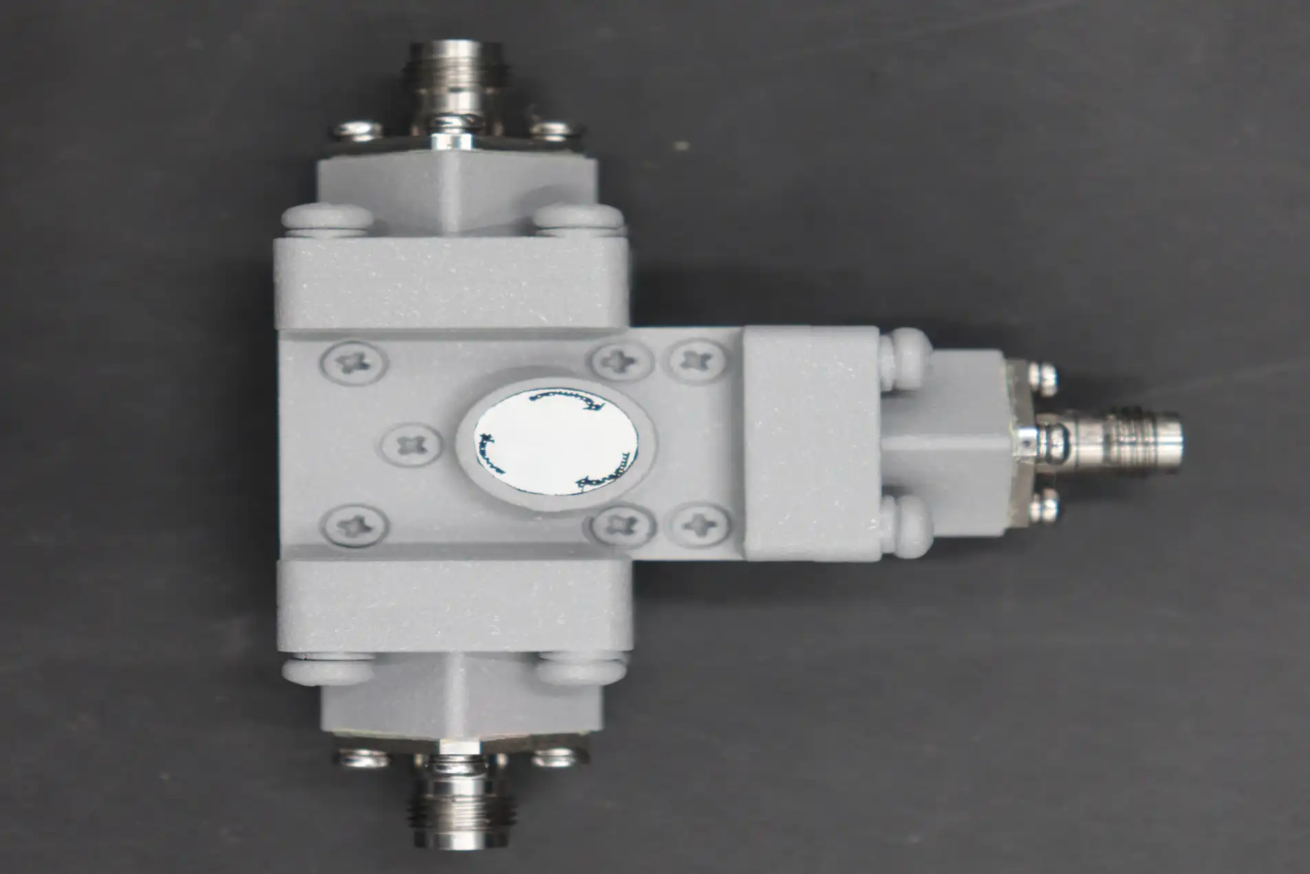
When these strategies are used with double-layer EMI shielding and gold-plated contact pins that don't change their resistance when they oxidize, broadband coaxial circulators can keep working properly for more than 10,000 hours. The insertion loss of a defense radar T/R module with temperature-compensated magnet assemblies and OFC cavities changed by less than 0.15 dB over 500 thermal cycles between -45°C and +85°C. This is in line with MIL-grade qualification data from published environmental stress screening protocols.

Comparing Broadband Coaxial Circulators and Alternative Solutions
Trade-Offs Across Device Types
There are real trade-offs in temperature efficiency when you choose between a wideband circulator, a narrowband circulator, an isolator, or a waveguide-based ferrite junction. Because the ferrite bias condition only needs to be kept at one center frequency, narrowband circulators are easier to keep stable over time. However, when an application needs to cover more than one band, they make the system more complicated because they need more devices, switch banks, and heat control for each part.
Waveguide circulators are better at handling high power and getting rid of heat through their metal body, but they are big and can't be used in small, coaxial-connected circuits. Isolators that are based on three-port circulators and have a closed dump port protect sources very well, but they don't allow for flexible routing and can't do duplexing.
When it comes to effectiveness, SWaP (Size, Weight, and Power) tuning is most important for broadband coaxial circulators. Different suppliers, like Narda, Pasternack, MECA Electronics, MACOM, Amphenol, Skyworks, Mini-Circuits, and Anaren, have different ways of managing heat. For example, MACOM focuses on making sure that ferrite materials are consistent, while Mini-Circuits offers bench-top form factors that are easy to use and come with documentation for their rated operating temperature. When evaluating any of these suppliers, procurement professionals should ask for specific thermal drift specifications instead of just room-temperature S-parameter data.
Procuring Broadband Coaxial Circulators with Optimal Thermal Performance
Specifying and Sourcing for Thermal Stability
If you're making a procurement specification for a broadband coaxial circulator that will be used in a temperature-sensitive environment, you can't just include general temperature values. A strict specification should include defined insertion loss changes with temperature (for example, a change of 0.15 dB from -45°C to +85°C), floor isolation at high and low temperatures (≥20 dB kept constant across the whole working range), thermal cycling endurance (number of cycles, ramp rates, rest times), and power handling with clear thermal derating curves.
Working together with suppliers during the planning phase pays off in ways that can't be recouped during the receiving inspection. ADM is one of those suppliers that can go from concept to production and keep their own measurement equipment up to 110 GHz. This way, suppliers can test thermal compensation methods with real data before placing large orders. Long-term ROI is better when the initial cost of purchase is weighed against lower failure rates in the field and less maintenance work over a number of years.
Defense and satellite supply chains must have after-sales support, paperwork that can be tracked, and material statements that are in line with RoHS. If a supplier's warranty terms cover performance loss caused by thermal drift, it shows that they are confident in their manufacturing process.
Best Practices and Recommendations for Engineers and Purchasing Managers
Thermal Validation Protocols and Operational Safeguards
Every broadband coaxial circulator used in mission-critical systems should go through an organized thermal validation process before it is put into use. Cycling the temperature between -55°C and +100°C, as required by MIL-STD-202 Method 107, for thermal shock testing shows weak solder joints and ferrite disk shifting that could cause the device to lose its tune over time. Thermal aging tests at high temperatures show that permanent magnet assemblies gradually lose their magnetization.
Keeping thermal coupling between high-dissipation parts and the circulator body to a minimum during installation increases the stable operating life. Physical separation from power amplifiers, regional thermal breaks, and airflow planning all work together to lower the ferrite assembly's peak temperature.
Continuous monitoring, especially keeping an eye on how insertion loss changes over time in systems that are already in use, lets you know when thermal drift builds up early, before it causes problems at the system level. For parts that break down because of heat, predictive maintenance schedules based on accumulated thermal cycles work better than calendar intervals.
Conclusion
Thermal drift is a problem that can be solved in design and procurement, not a limitation that can't be avoided. Engineers can choose parts that will keep working well over time if they know how ferrite magnetic properties, CTE mismatches, and resistance networks change when the temperature does. As standard engineering practice, ADM's broadband coaxial circulators include temperature-compensated magnet assemblies, OFC cavity machining, and aerospace-grade thermal robustness as standard engineering practice, covering DC to 40 GHz with insertion loss ≤0.3 dB and isolation ≥20 dB.
FAQ
What causes isolation to drop at high temperatures in a coaxial circulator?
As the temperature rises, the ferrite maximum magnetization drops. This moves the ferromagnetic resonance away from the planned bias point. This makes the non-reciprocal separation between the forward and backward signal routes smaller, which makes isolation smaller. Temperature-compensated magnet systems keep the strength of the bias field even when the temperature rises.
How do I verify a circulator's thermal stability before purchasing?
Ask for full S-parameter data across the rated temperature range, not just the specifications for room temperature. Ask for insertion loss variation curves and thermal cycling test reports that show the number of cycles and the widest and narrowest temperatures. If a supplier has their own temperature testing equipment, they can give you this information from real unit testing instead of modeling.
Does power handling change with temperature?
When the temperature of the environment is high, the temperature difference between the ferrite and the environment gets smaller, which makes it harder for the device to lose heat. High-power models with built-in copper heat sinks or ceramic thermal layers are better at reliably handling power across a wider range of temperatures.
Are RoHS-compliant circulators suitable for aerospace applications?
RoHS compliance controls the make-up of materials, especially lead-free solder and limited dangerous chemicals. It meets the standards for approval in aircraft and doesn't affect thermal or mechanical performance when the right ferrite and housing material are used.
Partner with ADM for Thermally Stable RF Circulator Solutions
The broadband coaxial circulator line from ADM is made for engineers who can't have performance surprises in the field. ADM makes circulators that are tested and proven to work in real-world thermal conditions. Their methods are ISO 9001-certified, and they can measure up to 110 GHz in-house. ADM is a reliable company that supplies broadband coaxial circulators to industrial, defense, and satellite markets around the world. They offer OEM customization, quick development, and committed technical support. Contact our engineering team at craig@admicrowave.com to discuss your application requirements.
References
1. Pozar, D. M. — Microwave Engineering, 4th Edition. John Wiley & Sons, 2011.
2. Lax, B., & Button, K. J. — Microwave Ferrites and Ferrimagnetics. McGraw-Hill, 1962.
3. IEEE Transactions on Microwave Theory and Techniques — Volume 68, Issue 9, 2020.
4. MIL-STD-202H — Test Method Standard: Electronic and Electrical Component Parts. U.S. Department of Defense, 2015.
5. International Journal of Microwave and Wireless Technologies — Cambridge University Press, Volume 13, 2021.
6. Helszajn, J. — Ferrite Phase Shifters and Control Devices. McGraw-Hill, 1989.
YOU MAY LIKE
 VIEW MORECircular Waveguide To Coaxial Adapter
 VIEW MOREWaveguide Unmatched Termination
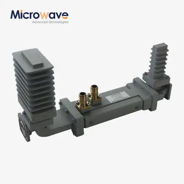 VIEW MOREHigh Power Waveguide Differential Phase Shift Isolator
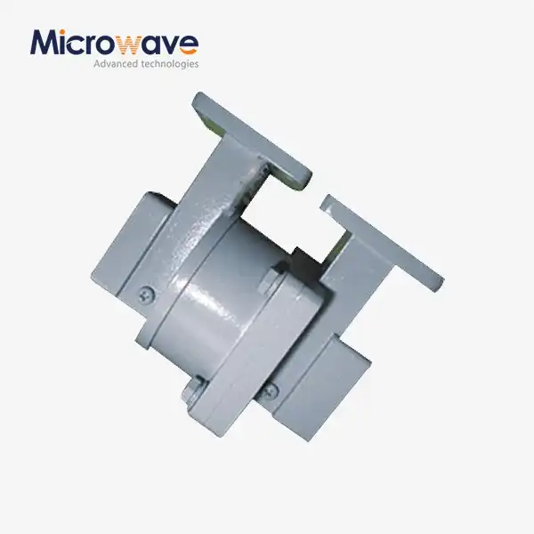 VIEW MOREWaveguide Single Channel Rotary Joint
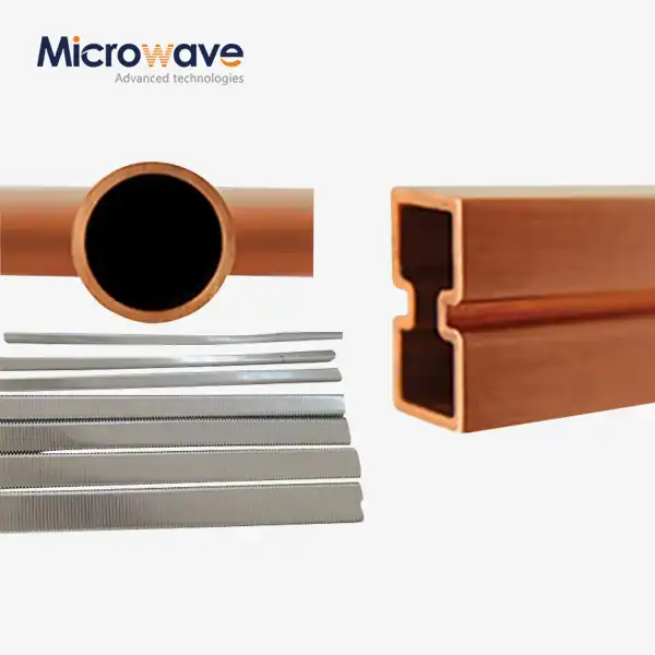 VIEW MOREWaveguide Tube
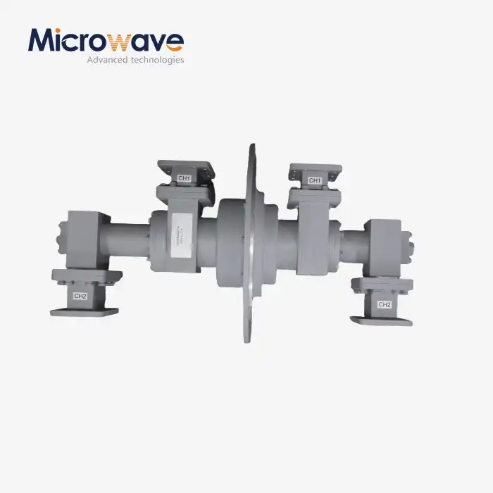 VIEW MOREDual Channel Coaxial Rotary Joint
 VIEW MOREFeed Fired Lens Antenna
 VIEW MORECassegrain Antenna
