


High Power Waveguide Assembly for Satellite and Radar Systems: Complete Guide
Modern satellite communication and radar systems are built around high-power waveguide assembly systems, which send electromagnetic data very efficiently at microwave and millimeter-wave frequencies. These special transmission lines are made up of thin metal tubes that are usually copper, aluminum, or brass. They let electromagnetic waves pass through them with little loss through internal reflection. Engineers and procurement teams depend on these units to handle kilowatts of RF power while keeping the purity of the signal in defense, aerospace, and telecommunications applications that need to be reliable and cannot be compromised.
Understanding High Power Waveguide Assembly: Fundamentals and Design Principles
We at Advanced Microwave Technologies Co., Ltd. have spent more than twenty years getting better at knowing what makes waveguide assemblies work in harsh situations. The main idea behind these systems is that they can focus and direct electromagnetic energy within a conductive border, which gets rid of the dielectric losses that come with cable options.
Core Components and Operating Physics
The science behind how waveguides work is based on boundary conditions that allow certain electromagnetic field patterns, which are called modes. When rectangular guides are used, the TE10 mode is the main transmitting mode because it has the lowest cut-off frequency. It moves through the hollow structure with electric field lines that are perpendicular to the direction of transmission. It bounces off the metal walls in a controlled way that keeps the phase coherent over long distances. A total assembly is made up of many carefully built parts that work together. The main way for transmission is made up of rigid waveguide assemblies, and mitered turns let the direction change without adding too many reflections. When signals need to be reoriented between components, twists let you change the polarization. To keep the needed return loss specs and stop signal leakage, the flanges—the important interface points—must be perfectly aligned. Our production methods, which are ISO 9001:2015 approved, make sure that these interfaces meet tolerances that are measured in thousandths of an inch.

Rigid Versus Flexible Configurations
Choosing between rigid and bendable designs affects both how hard it is to install and how reliable it will be in the long run. Rigid assemblies have better electrical performance and lower insertion loss (usually less than 0.3 dB per meter at X-band frequencies). This makes them perfect for stable placements with enough room for accurate alignment. These structures stay the same size even when the temperature changes a lot, which is very important for satellite ground sites that have to deal with yearly changes. Different technical problems can be solved with flexible waveguide assemblies. Their complicated metal structure lets them bend and twist a little, which keeps vibrations from getting through in flying radar systems or lets heat expand in high-power transmitter links. We make flexible parts that keep their electrical properties even after millions of flex cycles. These parts have been tested in our 24m microwave darkroom using our antenna plane near and far field measuring recombination chamber. Due to the interlocking design, it is important to pay close attention to the minimum bend radius requirements. Going beyond these limits results in lasting distortion that lowers VSWR performance.
Material Selection and Thermal Management
Material choices have a direct effect on waveguide assembly, how much power they can hold, and how long they last. Copper that has been silver-plated has the lowest surface resistance. This lowers ohmic losses, which turn RF energy into waste heat. Even though it has a little more attenuation, aluminum is lighter than steel, which is useful in aircraft uses where every gram counts. The cadence, power levels, and environmental exposure are used by our research team to choose the right materials. As power levels rise, thermal control becomes very important. Heat dissipation paths need to be carefully studied for high-power systems that handle kilowatts of continuous wave energy. We make sure that the parts we use have enough surface area and thermal conduction lines to avoid hot spots that could change the metal or break down the dielectric at the interfaces between the flanges. For some uses, the mechanical design needs to include channels for cooling liquid or forced air flow.
Design Considerations for High-Frequency Operation
As working frequencies rise into the Ka-band and beyond—where our test ranges up to 110 GHz—manufacturing tolerances get much tighter. At 10 GHz, surface roughness doesn't matter much, but at 40 GHz, it causes a lot of loss. Our high-precision CNC machine centers make internal measurements that are accurate to the micron level. This makes sure that the electrical performance is stable across the desired bandwidth. Another design factor to think about is moisture contamination. When water vapor condenses inside a waveguide assembly, it changes how insulating it is and makes the loss worse. Some systems use dry nitrogen purging to keep the internal environment under control, while sealed units have pressure release valves and desiccant ports. As part of our quality control procedures, we test for leaks to make sure the airtight closing is still good before delivery.
Comparing Waveguide Assemblies: Performance, Cost, and Application Fit
When making a procurement choice, you have to weigh a lot of different factors against the needs of the job and your budget. Engineers can improve system design by learning about the pros and cons of the different transmission line methods.
Waveguides Versus Coaxial Cables
When frequencies and power levels get higher, waveguide assemblies really start to show their benefits. When working in the X-band, a WR-90 waveguide has an insertion loss of about 0.04 dB per meter. At the same frequencies, even high-end coaxial lines have losses that are ten times higher. This big difference has a direct effect on how well the system works: less power is lost as heat, and weaker messages are kept with better signal-to-noise ratios. The ability to handle power shows an even bigger difference. Waveguide assemblies often deal with radar emitters' peak powers, which are measured in megawatts, and their constant power rates, which are in the kilowatt range. Voltage breakdown limits and temperature limits mean that coaxial wires can only handle a small amount of peak power compared to waveguides. And because of this, waveguide assemblies are the only real option for high-power amplifier outputs in satellite transfer sites.
Rigid Assembly Benefits and Installation Challenges
Rigid systems offer the most stable electricity performance of any type. Their set shape keeps phase changes from happening when they are moved mechanically, which is very important for phased array radar systems, where the accuracy of beam direction depends on the exact phase relationships between elements. This steadiness is what keeps weather radars that look for storm systems calibrated over years of nonstop use. Installation needs more thought than options that are more flexible. Each run has to be carefully measured, and parts have to be bent to fit around barriers and get to connection points. Our expert support team helps with planning the installation by giving you dimensional models and information on how to position the flanges. Careful construction costs money, but it pays off over and over again with decades of trouble-free use.
Flexible Assembly Applications
When installing something, flexibility is useful because rigid wiring isn't always realistic. Changing the way links are set up during development testing is helpful for prototype systems. Naval ships with gimbaled antenna systems need flexible parts that can handle constant movement without putting mechanical stress on parts that stay in place. On the other hand, they have a little more loss and can't handle as much power as the stiff versions. Also, flexible parts need to be checked every so often to make sure that the bending hasn't gone too far and caused tiredness. Our production standards include limits on both static and dynamic bend radius, as well as maximum twist angles that maintain electrical integrity.
Procurement Factors and Customization
Prices vary a lot depending on the frequency band, power rate, and level of customization needed. Standard catalog items with common flange types can be shipped quickly from stock, but custom waveguide assemblies need to be reviewed by engineers and have wait times for manufacturing. During the whole procurement process, we communicate clearly and give thorough quotes that break down the prices of tools, materials, and delivery times.If a project needs special flange designs, integrated mounting hardware, or weather sealing that goes beyond standard requirements, our OEM services can handle it. Procurement teams like that we can make prototypes and send working samples for testing before committing to large amounts for production. Volume pricing models honor orders that are bigger while still upholding the quality standards that our ISO certifications promise.
Applications and Benefits of High Power Waveguide Assemblies in Satellite and Radar Systems
Real-world uses show why these systems are still necessary, even though new technologies have come out. Their unique mix of low loss, high power capacity, and long-term dependability makes them perfect for problems that other solutions can't fix.
Satellite Communication Ground Infrastructure
High-power amplifiers are connected to antenna feeds at earth stations that connect ground networks to satellites in orbit using waveguide assemblies. Ku-band and Ka-band transfer systems send kilowatts of RF power into the sky. For every tenth of a decibel of loss, energy is lost, and the link margin is lowered. The signal strength stays strong through the last few meters between the amplifier and the antenna, so the effective radiated power, which affects transmission range and data throughput, is maximized. Low-loss communication is also good for downlink receive links. Picowatt-level weak signals from geostationary orbit make it through receive waveguide assembly runs to sensitive low-noise amplifiers without being harmed. Phase stability makes sure that signals from different antennas work well together in beam-forming networks. This controls receiving patterns to follow the positions of satellites across the arc.

Phased Array Radar Systems
Hundreds or thousands of separate radiating elements in a waveguide assembly are used in modern defense radar systems. Each one is fed by precise waveguide assemblies that keep exact phase relationships. In these situations, where design flaws have a direct effect on target recognition range and angular sharpness, our ability to customize the feed network really shines. The X-band feed networks we make for air traffic control radars have the beamforming accuracy needed to keep an eye on multiple planes at once while blocking out noise from the ground. Environmental resistance is needed for military observation radars that work in tough conditions. This is provided by a proper waveguide assembly building. When used in military sites or on expeditions, sealed assemblies don't rust from salt spray and can handle high and low temperatures. When compared to technologies that need to be replaced often, the long service life lowers the total cost of ownership.
Weather Monitoring Infrastructure
In open settings, meteorological radar devices that look for rain and other weather events are always on. Waveguide assemblies that connect transmitters to spinning antenna pedestals have to be able to handle millions of mechanical cycles without losing their accuracy. Our weather radar-specific movable parts are made from special materials that don't break down when exposed to UV light or when temperatures change from hot to cold in the summer and winter. These methods save lives by giving early warnings of bad weather because they work well. The procurement teams that are in charge of weather infrastructure, like how our paperwork can be tracked and how our after-sales support keeps systems running for decades.
Maintenance and Troubleshooting Guidelines
With proper upkeep, a waveguide assembly will last longer and keep working well. A visual check should be done to make sure that the flange connections are still tight and that the bend radius limits for the flexible parts have not been exceeded. In uses that need to be dry, pressure testing with dry nitrogen proves the integrity of the seal. With every delivery, we include full care guides with suggested inspection times and steps for fixing common problems. Using a vector network monitor to check the electrical performance can find degradation before system problems happen. Our expert team provides remote diagnostic help, analyzing S-parameter data to find issues and suggest ways to fix them.
Selecting and Procuring the Right High Power Waveguide Assembly
For buying to go well, the requirements must be very clear and match the assembly requirements to the application needs. During the design phase, our engineering team works with customers to make sure that the parts they choose work well with bigger systems.
Critical Selection Parameters
The most important thing to look for in a pick is frequency range matching. The internal dimensions of a waveguide assembly decide the frequency band it can support. If you try to operate outside of this range, either the signal will be cut off, or higher-order modes will start to propagate. The WR-90 guides work with X-band signals from 8.2 to 12.4 GHz, and the WR-28 guides work with Ka-band signals from 26.5 to 40 GHz. Our range of products covers the spectrum from L-band to W-band, waveguide assembly, and they can measure up to 110 GHz.Power handling specs need to take both peak and average power levels into account. Radar emitters send out short bursts with peak power of megawatts and average power that isn't very high. Communication systems, on the other hand, may use continuous waves at kilowatt levels. The safe working limits are set by the flange pressure values and the internal design. Going beyond these limits could cause arcing damage or thermal failure. Environmental factors affect the choice of material and the closing needs. Installations outside have to deal with changes in temperature, water, and UV rays. The environmental rules that our RoHS-compliant parts follow are met by surfaces that don't rust. Applications in space and the air need materials that are light and fit designs that can withstand shock, which can be proven by vibration tests.
Industry Supplier Landscape
There are a number of well-known companies that make microwave parts, and each has its own strengths. Global providers like Amphenol and TE Connectivity have a lot of products and a lot of ways to get them to customers. We at Advanced Microwave Technologies Co., Ltd are one of those specialized makers that focus on fine engineering and customization that standard catalog items can't offer. Quality approvals are an objective way to make sure that factory standards are met. Our ISO 9001:2015 certification shows that we handle quality in a planned way during planning, production, and delivery. The ISO 14001:2015 certification shows that we care about the environment, and the ISO 45001:2018 certification makes sure that our expert teams have a safe place to work.
Conclusion
High power waveguide assemblies are still an important part of satellite communication and radar systems that can't be reduced on performance. Because they have low loss, can handle a lot of power, and are reliable over time, they can solve transportation problems that other technologies can't. To make the right choice, you need to know what the application needs, compare performance traits, and work with makers who can provide quality and support throughout the product's existence. Innovations in materials, manufacturing, and design keep making things more useful, and efforts to be more environmentally friendly make sure that we are doing the right thing.
FAQ
What distinguishes high-power waveguide assemblies from standard RF transmission lines?
High-power systems have stronger hubs, better ways to get rid of heat, and materials that are specifically chosen to handle more power. These designs keep the power from dropping and control the heat that would normally damage standard parts. Power rates change based on frequency. With the right engineering, constant operation can go up to kilowatt levels, and peak handling can go up to megawatts.
How do I determine the correct waveguide size for my frequency band?
Each waveguide name is assigned a certain frequency range, and the WR number tells you the wide size in hundredths of an inch. To avoid shutdown or higher-order mode problems, the operating frequency must be in the approved band. Manufacturer datasheets give exact specs, and our engineering team helps you make the choice to make sure it works with everything else.
Can flexible waveguide assemblies replace rigid sections in all applications?
Flexible systems give up some electrical efficiency so they can be used in a variety of ways. Rigid design is best for applications that need total phase stability or the ability to handle the most power. Flexible parts are great when fixed handling isn't possible because of vibration separation, thermal expansion, or fitting issues. System design works best when applications are matched correctly.
Partner with ADM for Your Waveguide Assembly Requirements
Every unique waveguide assembly that Advanced Microwave Technologies Co., Ltd makes is the result of more than 20 years of skilled production. Our advanced technical tools, such as the 24m Microwave Darkroom with a measurement range of up to 110 GHz, allow us to do precise engineering that is backed by ISO 9001:2015, ISO 14001:2015, and ISO 45001:2018 certificates. Defense companies, satellite system developers, and research institutions can get OEM services from us that help them make custom solutions for their needs, from the prototype stage to mass production. Contact our engineering team at craig@admicrowave.com to talk about your project needs with a reliable waveguide assembly provider that cares about quality, flexibility, and quick technical support.
References
1. Pozar, David M. Microwave Engineering, 4th Edition. Hoboken: John Wiley & Sons, 2011.
2. Saad, Theodore S. Microwave Engineers' Handbook, Volume 1. Norwood: Artech House, 1971.
3. Montgomery, Carol G., Robert H. Dicke, and Edward M. Purcell. Principles of Microwave Circuits. London: Institution of Engineering and Technology, 1948.
4. Ramo, Simon, John R. Whinnery, and Theodore Van Duzer. Fields and Waves in Communication Electronics, 3rd Edition. New York: John Wiley & Sons, 1994.
5. Collin, Robert E. Foundations for Microwave Engineering, 2nd Edition. Hoboken: Wiley-IEEE Press, 2001.
6. Clarricoats, P.J.B. and A.D. Olver. Corrugated Horns for Microwave Antennas. London: Institution of Engineering and Technology, 1984.
YOU MAY LIKE
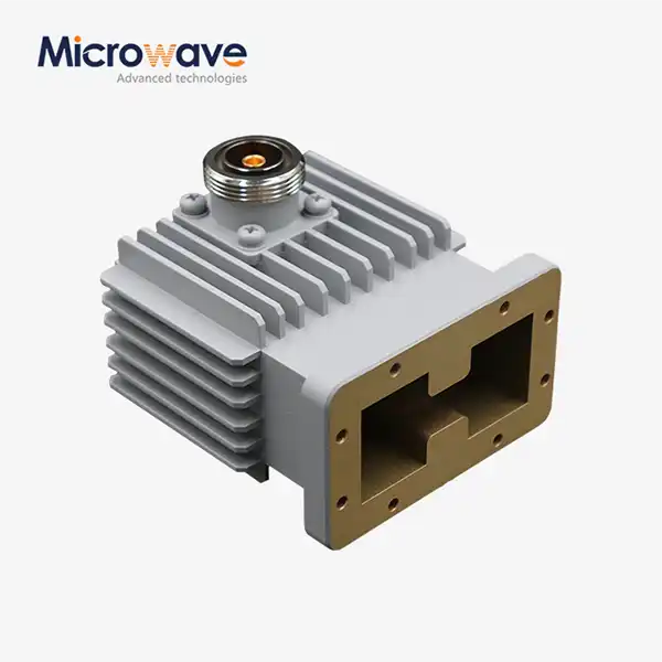 VIEW MOREHigh Power Waveguide to Coaxial Adapter
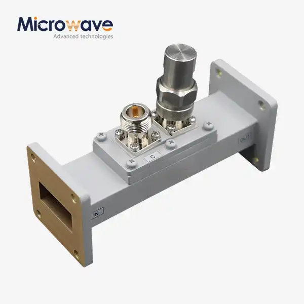 VIEW MOREWaveguide Loop Coupler
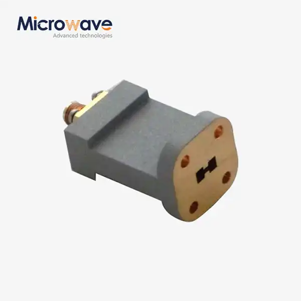 VIEW MOREEnd Launch Double Ridged WG To Coaxial Adapter
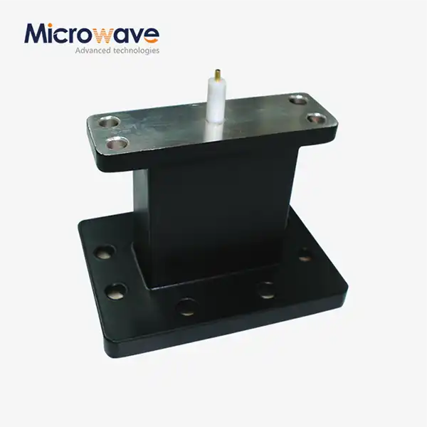 VIEW MOREEnd Launch Waveguide to Microstrip Adapter
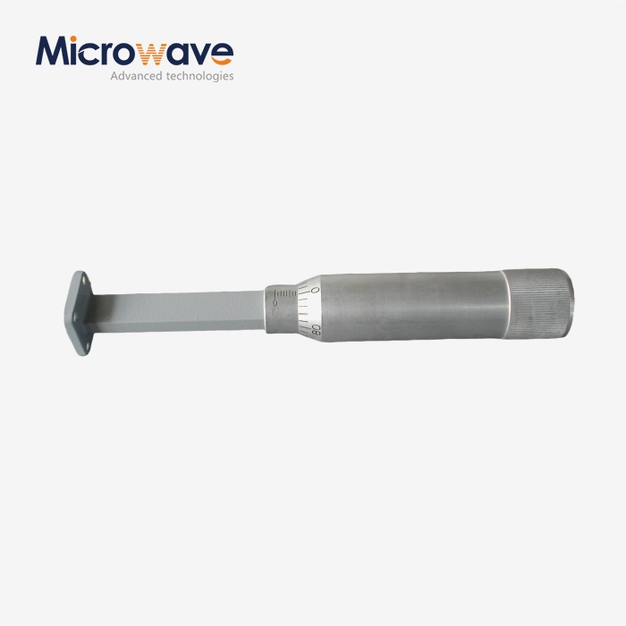 VIEW MOREWaveguide Sliding Termination
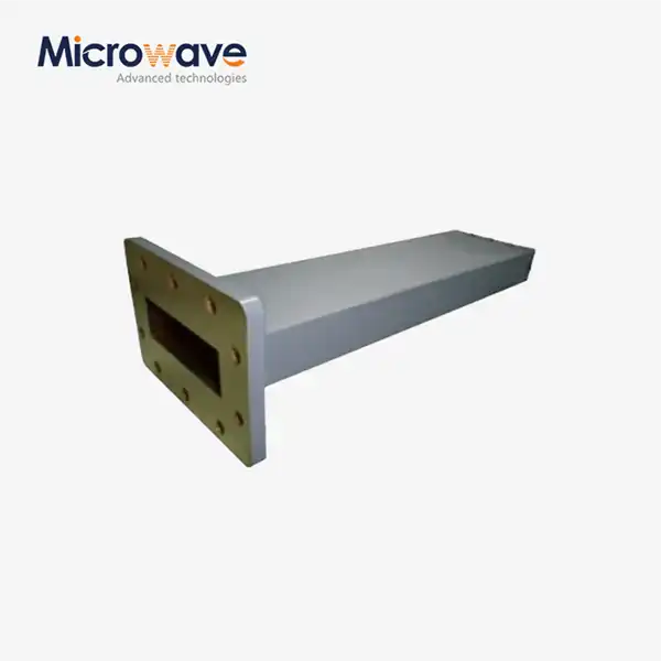 VIEW MOREWaveguide Unmatched Termination
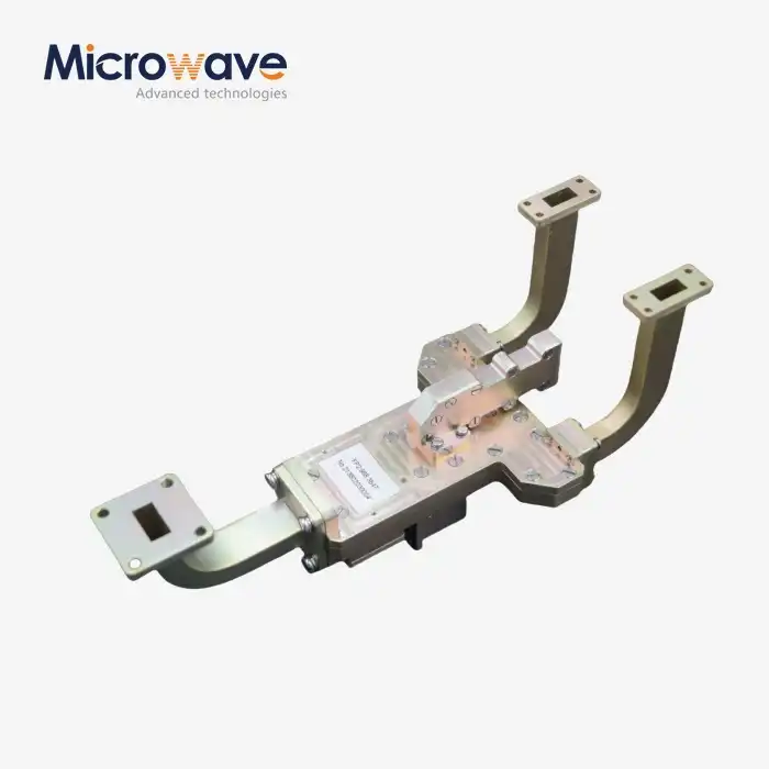 VIEW MOREMagic Hybrid Tee
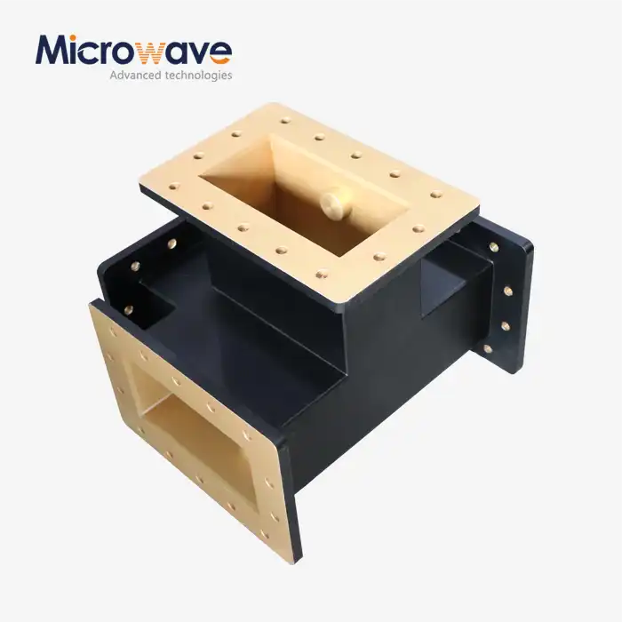 VIEW MOREH-Plane Tee
