Double Ridge Waveguide Versus Typical Waveguide
When choosing microwave transmission parts for wideband systems, the difference between normal rectangular waveguides and double ridge waveguide designs \ determines the structure of the system, double ridge waveguide, and the limits of its performance. The double ridge waveguide has metallic ridges that stick out from the wide walls. This creates a capacitive loading effect that lowers the dominant mode's cutoff frequency while keeping the waveguide's small size. This shape allows multi-octave bandwidth ratios to reach 2.4:1 to 3.6:1, which is higher than the 1.5:1 limit of regular rectangle guides. For procurement teams looking for parts for electronic warfare pods, wideband radar feeds, or RF test systems that need to cover all frequencies without mechanical switching, this structural difference directly means less system complexity, lower integration costs, and more operational flexibility from the C-band to the Ka-band.
Understanding Double Ridge Waveguides and Typical Waveguides
How electromagnetic energy moves through metal structures that are cut off is controlled by the basic structure of waveguide technology. When purchase engineers know about these structural differences, they can fit the features of the transmission line to the needs of the system without over-specifying or lowering performance.
What Defines a Double Ridge Waveguide
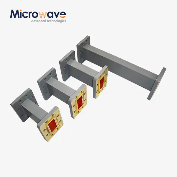
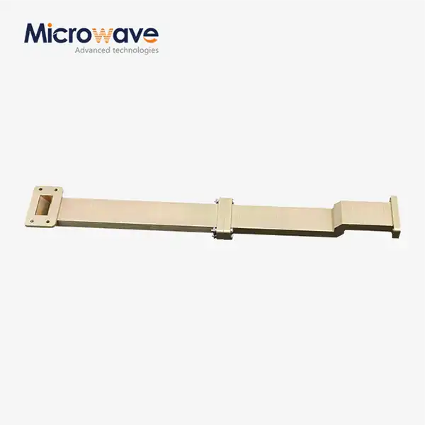
A double ridge waveguide is different from a regular rectangular waveguide because it has ridges running along the middle of both broad walls that are symmetrical. These bumps make the useful cross-sectional area smaller, which changes how the electromagnetic field is spread inside the guide. The exact height and width of the ridges are designed to lower the cutoff frequency while keeping single-mode function over a wide frequency range. Our ADM-500DRWAL line from Advanced Microwave Technologies Co., Ltd. shows this idea. It has a single component that covers 5–18 GHz and has a VSWR of less than 1.15. It is made from copper and has silver plating on it to reduce insertion loss across the whole band. Because the bumps add capacitive loads, the waveguide can work at frequencies where a rectangular waveguide of the same size would stop working. In other words, a double ridge joint can deal with lower frequencies while still having the same mechanical shape as a normal guide for higher frequencies. When making something, precise CNC cutting is needed to keep the ridge measurements within very small ranges. This is because even small changes can affect the impedance matching and VSWR performance.

Common Types of Typical Waveguides
Standard rectangular waveguides are used in most business and military microwave systems because they are easy to use and have well-documented performance properties. The cutoff frequency for these hollow metal tubes is set by the wide wall diameter alone, and they can support TE10 mode transmission. For example, the WR-90 works well from 8.2 to 12.4 GHz, with low loss and high power handling. However, it needs to be physically swapped when switching between nearby frequency bands. Waveguides that are circular can change polarization and are used in spinning joints for radar antennas and satellite ground connections. At the same frequencies, their TE11 mode properties give them lower attenuation than rectangular guides. However, at higher frequencies, where multiple modes can spread at the same time, it becomes harder to keep the mode purity. One ridge is placed along a single broad wall in single ridge waveguides, which are a middle option. Even though they have a wider bandwidth than rectangular guides, their uneven double ridge waveguide field patterns can make system integration harder than with double ridge designs, which have a balanced shape.
Structural and Electromagnetic Distinctions
How ridge shape changes the spread of electromagnetic fields is what makes them different. When you look at rectangular waveguides, the strongest electric field is in the middle of the wide wall. As you move toward the narrow walls, the field gets weaker. Because there are two ridges, the electric field is concentrated in the small space between the tips of the ridges. This makes the effective capacitance per unit length higher. This field focus means a lot of different things. When compared to standard rectangular guides, which have a characteristic impedance of 500 to 600 ohms, a double ridge waveguide has a characteristic impedance of 200 to 400 ohms. At lower frequencies, lower resistance usually means better power handling, but peak power capacity goes down because the gaps between the ridges get smaller. When the frequency changes, the phase velocity in ridged waveguides changes more than in rectangular ones. This changes the group delay features. In wideband systems, where keeping the signal's consistency across multi-gigahertz bandwidths is very important, this spread must be taken into account.
Performance Comparison: Double Ridge Waveguide vs Typical Waveguides
To find the exact changes in performance between waveguide designs, you need to look at their bandwidth, insertion loss, power handling limits, and mechanical integration factors. These measures have a direct effect on how systems are designed and the total cost of ownership over the span of a product.
Bandwidth and Frequency Coverage Analysis
Standard rectangular waveguides work well up to about 1.5:1 frequency ratios, but their performance starts to drop when higher-order modes start to operate. This is shown by WR-137, which works in the 5.85–8.20 GHz band. To move to the nearby 8.20–12.40 GHz band, you have to switch to WR-90, which means you have to buy more parts, set up mechanical connections, and could have system downtime while you do this. A double ridge waveguide greatly increases the frequency that can be used. With a 3:1 ratio, our ADM-250DRWAL series covers 2.6-7.8 GHz in a single unit. The ADM-1100DRWAL series covers 11-26.5 GHz with a 2.4:1 ratio. In devices like broadband spy monitors, spectrum analyzers, and frequency-agile electronic countermeasure systems, this ability to switch between octaves gets rid of the need for band-switching hardware. To keep VSWR below 1.2 over such a large range, the ridge profile and flange design need to be carefully optimized. This is where production accuracy is very important. At the same frequencies, the trade-off shows up as more loss per unit length compared to rectangular guides. At 10 GHz, a WR-90 rectangular guide shows about 0.02 dB/meter, while a similar double ridge guide could show between 0.04-0.06 dB/meter. This difference isn't very important for short runs like antenna lines or test setups, but for long distribution systems, link budgets need to take cumulative loss into account.
Signal Integrity and Loss Characteristics
In waveguide systems, insertion loss is mostly caused by wire losses; in air-filled guides, dielectric losses are almost nonexistent. Material conductivity and surface finish determine how well a material loses heat. Silver plating, which is standard on our copper-body parts that work above 5 GHz, lowers skin-effect losses compared to bare copper or aluminum. Below 5 GHz, bare copper or aluminum is fine with chromate conversion coating for corrosion protection. In double ridge designs, the concentrated electric fields between the ridge tips make the current levels higher along the sides of the ridges. This slightly raises ohmic losses. But being able to work in single-mode situations over such wide bandwidths often makes up for this disadvantage. In a normal system, the extra 0.5 dB of total loss could be worth getting rid of two waveguide switches and the insertion loss, dependability issues, and control complexity that come with them. The VSWR performance has a direct effect on the reflected power and the efficiency of the system. Our standard requirements say that the VSWR must be ≤1.15 below 11 GHz and ≤1.2 for millimeter-wave bands. To meet these requirements, the flanges must be precisely lined up, and dowel pins must be used to make sure that the rotating parts of two modules fit together correctly. Ridge-to-ridge mismatch causes capacitive steps that lower VSWR, so it's very important to control mechanical tolerances during production and assembly.
Power Handling and Mechanical Integration
Waveguides can only hold a certain amount of power before the voltage breaks down in the space between the wires. When compared to rectangular guides, double ridge designs have lower double ridge waveguide breakdown limits because the space between the ridge tips is closer together. A WR-90 guide can handle power levels of up to kilowatts for continuous waves and up to megawatts for burst radar. Similar double ridge systems may be rated for hundreds of watts CW, but they can handle almost rectangular amounts of power when pressurized with dry nitrogen or SF6 gas. When it comes to integration, double ridge waveguides often save room by getting rid of the need for switching systems. A wideband EW receiver front-end with ridged parts takes up less space and weighs less than a similar multi-band system with mechanical band changes. This benefit is strong for flying systems that have to make design choices based on their size, weight, and power (SWaP). When buying, you need to pay attention to how well the flanges work together. Rectangular waveguides use UG-series or MIL-standard flanges, but double ridge systems use custom flange designs (like our FP/FM configurations) that are made for the shape of the ridges. To make sure that parts from different makers can work together, the specifications must be carefully looked over, and if possible, qualification testing must be done before the full rollout.
Key Benefits of Double Ridge Waveguides for Global B2B Clients
By turning technical features into operational benefits, system engineers can better understand why double ridge waveguide technology is being chosen more and more for difficult applications. The benefits go beyond just specifying the speed; they also include lower costs, better dependability, and better performance at the system level.

Multi-Band Functionality and System Simplification
Using a single communication line to work across multiple frequency allocations gets rid of the need for complicated gear. An X-band (7.9–8.4 GHz) and C-band (3.7–4.2 GHz uplink and 5.925–6.425 GHz downlink) satellite ground station doesn't need diplexers, band-switching relays, or dual rectangular waveguide runs. Instead, it can use a double ridge feed network. This cuts down on the number of parts needed, the amount of work needed to put them together, and the stability of the system by getting rid of mechanical switch wear-out mechanisms. With wideband ridged waveguide feeds, defense companies can make multi-function RF systems that can handle transmission, electronic warfare, and signal intelligence bands all at the same time within a single aperture. Compared to standard narrowband methods that need different modules for each frequency regime, the design simplification speeds up development times and lowers one-time engineering costs. Test and measurement applications gain a lot. In anechoic rooms from 2 to 40 GHz, reference sources are broadband horn antennas fed by double-ridge waveguides. There are no physical changes to the antennas. Calibration time goes down, measurement uncertainty goes down because the standard features stay the same, and facility output goes up. When companies measure antenna patterns, test radomes, or characterize RCS, they find that these operating improvements directly lead to lower project costs and faster turnaround times.
Customization Capabilities and Application-Specific Solutions
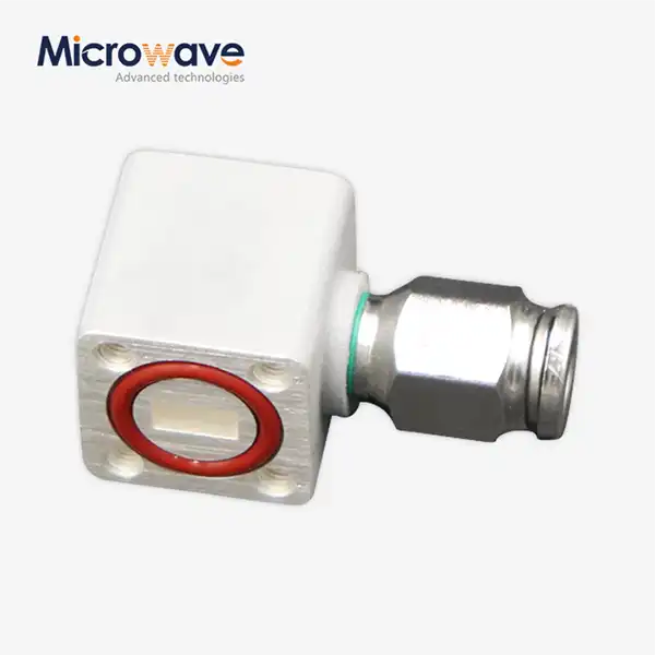
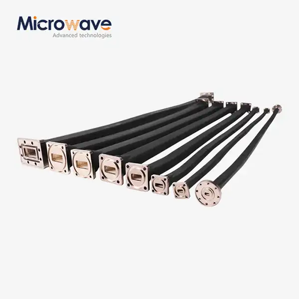
Many uses can be met by standard stock items, but mission-critical systems often need custom specs. Advanced Microwave Technologies Co., Ltd. offers OEM services that let you change the ridge shapes, clamp types, mounting arrangements, and levels of environmental protection. When a customer needs to be able to work at 60,000 feet and with temperature changes between -55°C and +125°C, they are given different material choices and covering requirements than when the application is in a lab. Length tuning takes into account how certain systems are set up. Our basic assemblies come in sizes from 10 mm to 500 mm, but we can also make custom shapes to fit the size of the equipment that needs to be packed. Integrated transitions to coaxial connectors, rectangular waveguides, double ridge waveguides, or specialty interfaces like orthomode transducers can be built directly into assemblies. This means that extra adapters are not needed, and the loss and VSWR degradation that comes with them are not as bad. Choosing the material adds another level of personalization. For bands below 5 GHz, where conductivity standards are less strict, aluminum with a chromate conversion coating is a lightweight and cost-effective option. Copper that has been plated with silver or gold works best for electrical purposes at higher frequencies. For corrosive settings like marine radars and coastal monitoring systems, better passivation processes or different platings make sure that the equipment will last for a long time without breaking down from salt spray or humidity.
Lifecycle Cost and Reliability Advantages
The total cost of ownership includes more than just the price of buying something. It also includes the work needed to install it, how reliable it is in use, and the upkeep that it needs. A wideband double-ridge system might cost more per unit than a single rectangular waveguide, but it doesn't need as many band-specific parts, switching hardware, control systems, or wires to link them. It's easier to install because there is only one waveguide run instead of multiple parallel lines with supporting structures. Cutting down on the number of parts makes things more reliable. There are different ways that each part of an RF chain could fail: plugs can come loose, switches can break after being cycled many times, and wires can sometimes short out. These weaknesses can't happen with an efficient design that uses rigid waveguides. Military systems that are subject to shock, pressure, and changes in temperature can benefit greatly from the natural durability of all-metal waveguide design, which doesn't have any moving parts or interfaces that wear out quickly. Maintenance times get longer when systems have fewer parts that can be changed or that need to be replaced. Since there are no band-switching switches, there is no need to clean and change the contacts on a regular basis. Solid-state systems that don't have any mechanical tuning parts only need to be checked for VSWR every so often instead of being realigned all the time. Lifecycle cost benefits are big over a 20-year operational life, which is common in defense and aerospace uses, even though the original investment is higher.
Conclusion
Choosing between double-ridge waveguides and standard rectangular designs has a big impact on the layout of a microwave system, affecting its frequency, number of parts, ease of integration, and overall costs over its lifetime. Double ridge technology increases the frequency ranges that can be used to multiple octaves. It does this by getting rid of mechanical switching hardware and making installation easier. However, it comes with trade-offs in insertion loss and power handling that are fine for most wideband applications. When making a purchase decision, technical specifications should be weighed against commercial factors such as the supplier's capabilities, lead times, and long-term support. It is important to keep in mind that the cheapest component is rarely the best choice for a system when integration, labor, reliability, and maintenance needs are all taken into account.
FAQ
What frequency range advantage does a double-ridge waveguide offer?
Standard rectangular waveguides only get 1.5:1 frequency ratios in single units, but double ridge waveguide designs can get 2.4:1 to 3.6:1 frequency ratios. This means that parts like our ADM-500DRWAL can work with frequencies from 5 to 18 GHz without having to change any hardware. This gets rid of the need for band-switching methods that are needed when using multiple rectangular waveguides for similar ranges.
How does insertion loss compare between the two types?
At the same frequencies, double ridge waveguides have a slightly higher loss per unit length—usually between 0.04-0.06 dB/meter compared to 0.02 dB/meter for rectangular guides. But system-level loss often goes down because rigid designs get rid of waveguide switches and the connections that go with them, which would add 0.5 to 1 dB per transition point otherwise.
Can double-ridge waveguides handle high-power applications?
Because there is less space between the ridge tips, the peak power capacity is lower than with rectangular guides. However, pressurizing with dry nitrogen or SF6 gas greatly raises the breakdown limits. When rigid assemblies are built correctly, they can handle up to kilowatts of constant power and megawatts of peak power for most wideband EW, test, and communication tasks.
Partner with ADM: Your Trusted Double Ridge Waveguide Supplier
Advanced Microwave Technologies Co., Ltd. has been making high-quality products for over 20 years and offers full engineering help to make precise double ridge waveguide solutions for tough uses. Our ISO 9001:2008-certified production facilities and RoHS-compliant processes make sure that the quality is always the same. Additionally, our 24-meter microwave lab lets us test up to 110 GHz, so you can be sure that the performance you receive is perfect. We make custom double-ridge waveguide systems that meet your exact frequency, power, and environmental needs. Our experienced engineers work with you throughout the whole design process. Whether you need a few prototypes to test an idea or a lot of them for full-scale production, our flexible manufacturing can work with projects at any stage. Contact craig@admicrowave.com right away to talk about your wideband transmission line needs and find out how working with a dedicated double ridge waveguide manufacturer can make your procurement process easier while also giving you better technical performance for use in research, military, aerospace, and telecommunications.
References
1. Southworth, G. C., "Principles and Applications of Waveguide Transmission," Van Nostrand Technical Books, 1950.
2. Matthaei, G. L., Young, L., and Jones, E. M. T., "Microwave Filters, Impedance-Matching Networks, and Coupling Structures," Artech House, 1980.
3. Hopfer, S., "The Design of Ridged Waveguides," IRE Transactions on Microwave Theory and Techniques, October 1955.
4. Cohn, S. B., "Properties of Ridge Waveguide," Proceedings of the IRE, August 1947.
5. Collin, R. E., "Field Theory of Guided Waves, Second Edition," IEEE Press Series on Electromagnetic Wave Theory, 1991.
6. Montgomery, C. G., Dicke, R. H., and Purcell, E. M., "Principles of Microwave Circuits," MIT Radiation Laboratory Series Volume 8, McGraw-Hill, 1948.