Everything You Need to Know About Custom Waveguide E Bend Solutions
When signal integrity collapses due to improper directional transitions in your high-frequency microwave system, critical missions fail. Custom Waveguide E Bend solutions address this exact challenge by enabling precise signal routing while maintaining exceptional performance across demanding applications in satellite communications, aerospace, and defense systems. Understanding how to select, customize, and implement the right Waveguide E Bend configuration can mean the difference between mission success and catastrophic system failure in environments where reliability is non-negotiable.
Understanding Waveguide E Bend Fundamentals and Their Critical Role
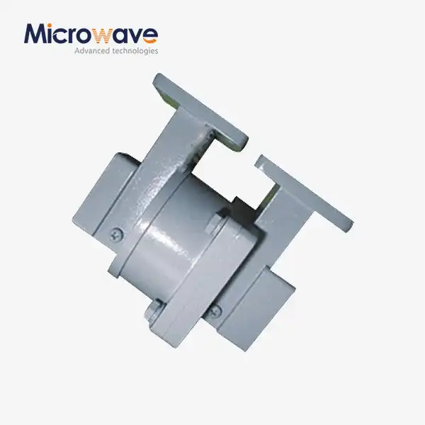
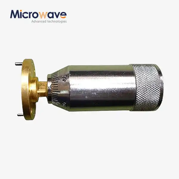
The Waveguide E Bend represents a cornerstone component in modern microwave engineering, functioning as a precision-engineered directional transition that enables electromagnetic signals to change direction within the E-plane of the waveguide structure. Unlike simple mechanical bends, these specialized components are meticulously designed to maintain consistent impedance throughout the transition, preventing signal reflections that would otherwise degrade system performance. The fundamental principle behind Waveguide E Bend operation involves carefully calculated geometric parameters that ensure the electromagnetic wave propagates smoothly through the curved section without generating higher-order modes or experiencing significant attenuation. In high-frequency applications ranging from satellite ground stations to military radar installations, the Waveguide E Bend serves an indispensable function by allowing engineers to route signal paths around obstacles, connect equipment mounted at different orientations, and create compact system architectures without compromising signal quality. The precision required in these components cannot be overstated, as even minor deviations in the bend radius or cross-sectional dimensions can introduce unacceptable levels of return loss or phase distortion. Advanced manufacturing techniques, including CNC machining and precision casting, enable producers to achieve the tight tolerances necessary for reliable operation across the intended frequency range.

Key Performance Parameters That Define Quality
When evaluating Waveguide E Bend solutions, several critical performance parameters must be carefully considered to ensure optimal system integration. The Voltage Standing Wave Ratio (VSWR) serves as perhaps the most fundamental indicator of component quality, with high-performance bends typically achieving values of 1.15 or better across their operating bandwidth. This low VSWR indicates minimal signal reflection, ensuring that transmitted power reaches its destination rather than bouncing back toward the source. Insertion loss represents another crucial specification, quantifying the signal attenuation introduced by the bend itself, with premium components maintaining insertion loss below 0.1 dB across their frequency range. The frequency range compatibility of a Waveguide E Bend directly determines its applicability to specific systems, with modern designs supporting operations from microwave frequencies extending up to 110 GHz and beyond into the millimeter-wave spectrum. Material selection plays an equally important role in determining both electrical and mechanical performance characteristics. Aluminum alloys offer an excellent balance of weight, conductivity, and machinability for most applications, while brass and copper variants provide enhanced electrical performance for the most demanding requirements. Surface finishing treatments such as silver or gold plating further reduce resistive losses and improve corrosion resistance in harsh operational environments.
Design Considerations for Custom Configurations
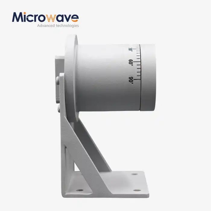
Custom Waveguide E Bend design demands a sophisticated understanding of electromagnetic theory combined with practical manufacturing constraints. The bend radius represents the most critical geometric parameter, requiring careful optimization to balance physical size constraints against electrical performance requirements. Tighter bend radii enable more compact system designs but increase the risk of mode conversion and higher insertion loss, while larger radii improve electrical performance at the expense of system footprint. Engineers must carefully evaluate these trade-offs based on specific application requirements, considering factors such as available mounting space, system weight limitations, and performance specifications. The bend angle configuration offers significant flexibility, with standard options including 45-degree and 90-degree bends, while custom angles can be precisely manufactured to meet unique routing requirements. Multi-degree bend assemblies combine multiple directional changes within a single integrated component, reducing the number of flange connections and thereby minimizing potential sources of signal degradation. These complex assemblies require sophisticated design tools and manufacturing capabilities to ensure that accumulated phase shifts and impedance variations remain within acceptable limits. Advanced electromagnetic simulation software enables engineers to predict component behavior before physical prototyping, significantly reducing development time and ensuring first-pass design success.
Advanced Materials and Manufacturing Excellence
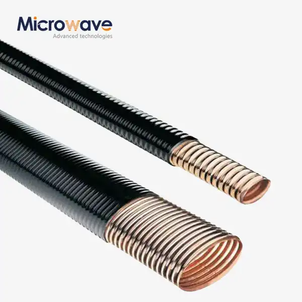
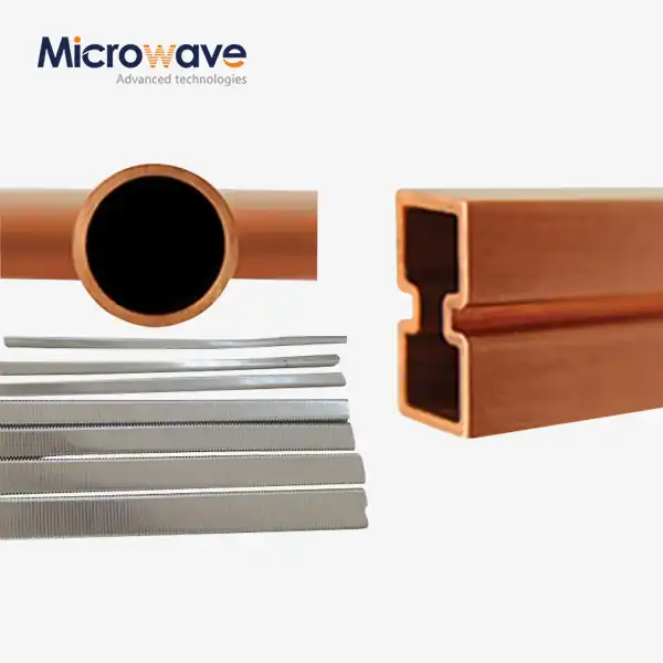
The selection of appropriate materials for Waveguide E Bend construction profoundly impacts both immediate performance characteristics and long-term reliability in field conditions. High-purity aluminum alloys, particularly 6061-T6, represent the industry standard for most applications, offering excellent electrical conductivity combined with favorable mechanical properties and corrosion resistance. The material's natural oxide layer provides inherent protection against environmental degradation, while its relatively low density contributes to weight reduction in aerospace applications where every gram matters. Precision CNC machining of aluminum enables the achievement of tight dimensional tolerances essential for maintaining consistent electrical performance across production batches. For applications demanding the absolute highest electrical performance, oxygen-free high-conductivity (OFHC) copper provides superior conductivity that translates directly into reduced insertion loss and improved power handling capability. The enhanced conductivity of copper becomes particularly important at higher frequencies where skin depth effects concentrate current flow near the conductor surface. However, copper's greater weight and susceptibility to oxidation require careful consideration of application-specific trade-offs. Brass variants offer an interesting middle ground, combining good electrical properties with excellent machinability and corrosion resistance, making them suitable for applications where moderate performance requirements intersect with challenging environmental conditions.
Surface Treatment Technologies for Enhanced Performance
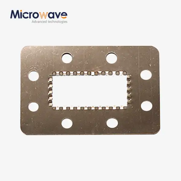
Advanced surface finishing techniques transform raw machined Waveguide E Bend components into precision instruments capable of reliable operation across their full performance envelope. Silver plating represents the gold standard for microwave applications, providing the lowest resistive losses due to silver's exceptional electrical conductivity while simultaneously offering excellent solderability for subsequent assembly operations. The typical plating thickness ranges from 5 to 10 microns, sufficient to exceed multiple skin depths across the operating frequency range while avoiding excessive cost or weight penalties. Specialized undercoating treatments ensure robust adhesion of the silver layer to the base metal substrate, preventing delamination under thermal cycling or mechanical stress. Gold plating serves niche applications where the absolute best corrosion resistance is required, such as in maritime environments or long-duration space missions where component replacement is impractical or impossible. While gold's electrical conductivity is slightly lower than silver's, its chemical stability remains unmatched, ensuring consistent performance over decades of operation in harsh conditions. The Waveguide E Bend manufacturing process concludes with rigorous quality control procedures including dimensional verification, visual inspection, and electrical testing to validate that each component meets or exceeds specified performance requirements before shipment to customers.
Application-Specific Solutions Across Industries
Satellite communication systems represent one of the most demanding application environments for Waveguide E Bend technology, where component reliability directly impacts mission success over operational lifetimes measured in years or decades. Ground station installations utilize these components extensively for routing signals between antenna feeds, low-noise amplifiers, frequency converters, and transmission equipment while maintaining the exceptionally low noise figures required for detecting weak signals from space. The Waveguide E Bend configurations in these systems must handle substantial power levels during transmission while simultaneously preserving signal integrity during reception, often operating across multiple frequency bands to support diverse communication protocols. Aerospace and defense applications impose even more stringent requirements, combining electrical performance specifications with extreme environmental conditions including wide temperature ranges, vibration, shock, and exposure to humidity or salt spray. Military radar systems depend on Waveguide E Bend components to route signals through complex antenna structures while maintaining the precise phase relationships necessary for beamforming and target discrimination. The reliability requirements in these applications cannot be overstated, as system failures in combat environments can have life-or-death consequences for personnel depending on equipment performance. Custom designs frequently incorporate specialized features such as thermal compensation mechanisms, enhanced mechanical mounting provisions, and hermetic sealing to ensure robust operation under the most challenging conditions.
Telecommunications Infrastructure and 5G Networks
The explosive growth of telecommunications infrastructure, particularly the deployment of 5G networks operating at millimeter-wave frequencies, has created unprecedented demand for high-performance Waveguide E Bend solutions. Base station installations require compact, lightweight components capable of operating efficiently across the expanded frequency ranges used by next-generation wireless systems. The Waveguide E Bend designs for these applications must balance electrical performance against practical considerations including installation complexity, maintenance accessibility, and environmental exposure over multi-year operational lifespans. Innovative designs incorporate features such as integrated mounting provisions and weather-resistant coatings to facilitate rapid deployment and reduce total cost of ownership. Industrial Internet of Things (IoT) applications increasingly rely on microwave communication links for connecting remote sensors, monitoring equipment, and control systems across vast geographic areas. These installations demand cost-effective Waveguide E Bend solutions that maintain reliable performance while meeting budget constraints typical of commercial deployments. Standardized designs covering common frequency bands and bend configurations enable volume production economies that benefit end users through reduced per-unit costs without sacrificing the quality and reliability necessary for dependable long-term operation in unmanned installations.

Customization Capabilities and OEM Services
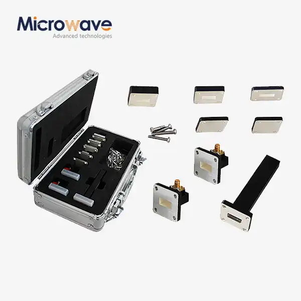
Advanced Microwave Technologies Co., Ltd has established comprehensive customization capabilities that transform standard Waveguide E Bend designs into application-specific solutions precisely matched to customer requirements. The engineering team works collaboratively with clients from initial concept development through final production, leveraging over two decades of microwave experience to guide design decisions and optimize component specifications. This consultative approach ensures that custom solutions not only meet stated electrical requirements but also consider practical factors including manufacturing feasibility, cost targets, and integration with existing system architectures. The customization process begins with detailed requirements analysis, where engineers evaluate application-specific parameters including frequency range, power handling requirements, physical size constraints, environmental conditions, and interface specifications. Advanced electromagnetic simulation tools enable rapid evaluation of design alternatives, allowing the team to optimize critical parameters such as bend radius, cross-sectional dimensions, and material selection before committing to physical prototyping. This simulation-first approach dramatically reduces development time and cost while increasing confidence in first-article success. The company's state-of-the-art 24-meter microwave darkroom facility, equipped with Antenna Plane Near and Far Field Measuring Recombination Chamber technology, provides unmatched capabilities for validating component performance across frequency ranges from 0.5 to 110 GHz.
Prototyping Through Production Excellence
Rapid prototyping capabilities enable customers to evaluate custom Waveguide E Bend designs under actual operating conditions before committing to volume production. The flexible manufacturing infrastructure supports low-volume prototype runs with lead times measured in weeks rather than months, facilitating iterative design refinement when application requirements evolve during system development. Once prototype validation is complete, seamless transition to production volumes ensures consistency between prototype and production units while leveraging economies of scale to optimize per-unit costs for commercial deployments. Quality control procedures throughout the manufacturing process ensure that every Waveguide E Bend component, whether prototype or production unit, meets specified performance requirements. Dimensional inspection using precision metrology equipment verifies that critical geometric parameters remain within tight tolerances, while electrical testing validates VSWR, insertion loss, and other key performance parameters across the full operating frequency range. The company's ISO 9001:2015 certification provides systematic quality management throughout all phases of production, from raw material procurement through final shipping, giving customers confidence in receiving components that perform reliably over their full operational lifetime.
Conclusion
Custom Waveguide E Bend solutions deliver mission-critical performance for applications demanding uncompromising signal integrity and reliability across satellite communications, aerospace, defense, and telecommunications sectors.
Cooperate with Advanced Microwave Technologies Co., Ltd.
Partner with a China Waveguide E Bend manufacturer combining 20+ years expertise with cutting-edge 24m microwave darkroom testing capabilities. As a leading China Waveguide E Bend factory and China Waveguide E Bend supplier, we deliver High Quality Waveguide E Bend solutions with competitive Waveguide E Bend price points. Our China Waveguide E Bend wholesale programs and custom Waveguide E Bend for sale meet diverse specifications from WR10 through WR430, with testing up to 110 GHz. ISO 9001:2015 and RoHS certified manufacturing ensures reliable performance for your critical applications. Contact craig@admicrowave.com today for technical consultation and customized quotations. Bookmark this resource for future reference when specifying waveguide components for your next project.
References
1. Pozar, David M. "Microwave Engineering" 4th Edition, John Wiley & Sons - Comprehensive treatment of waveguide theory and bend design principles
2. Marcuvitz, Nathan "Waveguide Handbook" Institution of Engineering and Technology - Classic reference for waveguide component design and analysis
3. Balanis, Constantine A. "Advanced Engineering Electromagnetics" John Wiley & Sons - Detailed electromagnetic field analysis applicable to waveguide structures
4. IEEE Standard 1785-2014 "Rectangular Waveguides - Part 1: General Requirements and Test Procedures" Institute of Electrical and Electronics Engineers - Industry standards for waveguide component specification and testing