Elliptical Microwave Waveguides vs Rectangular: Loss Compared
When looking at signal loss in microwave transmission systems, elliptical microwave waveguides usually have 15–30% less insertion loss than rectangular ones at frequencies above 18 GHz. Their better performance comes from their corrugated shape, which lowers wall current density and mode conversion losses. Advanced Microwave Technologies engineers have noticed that elliptical designs have better VSWR performance—often below 1.15:1 across operational bands—while rectangular waveguides need more flange connections, which add reflection points and total loss in long-distance installations.
Understanding Microwave Waveguides: Elliptical vs. Rectangular
Choosing between elliptical microwave waveguides and rectangular shapes is a big decision that affects how well the system works, how flexible it is to install, and how much it costs to own the whole thing. Elliptical and rectangular cross-sections of metal tubes interact with microwave signals in different ways, leading to measured differences in attenuation, power handling, and mechanical flexibility.
Structural and Geometric Differences
Since the 1940s, rectangular waveguides have been the most common type of microwave waveguide because they are easy to make and have well-studied propagation properties. The internal measurements of these solid metal tubes stay the same. They are usually given standard EIA names like WR-90 or WR-28, which show the cutoff frequency and single-mode bandwidth. To get tight specs on the wide and narrow wall measurements during manufacturing, precision machining or electroforming is used.
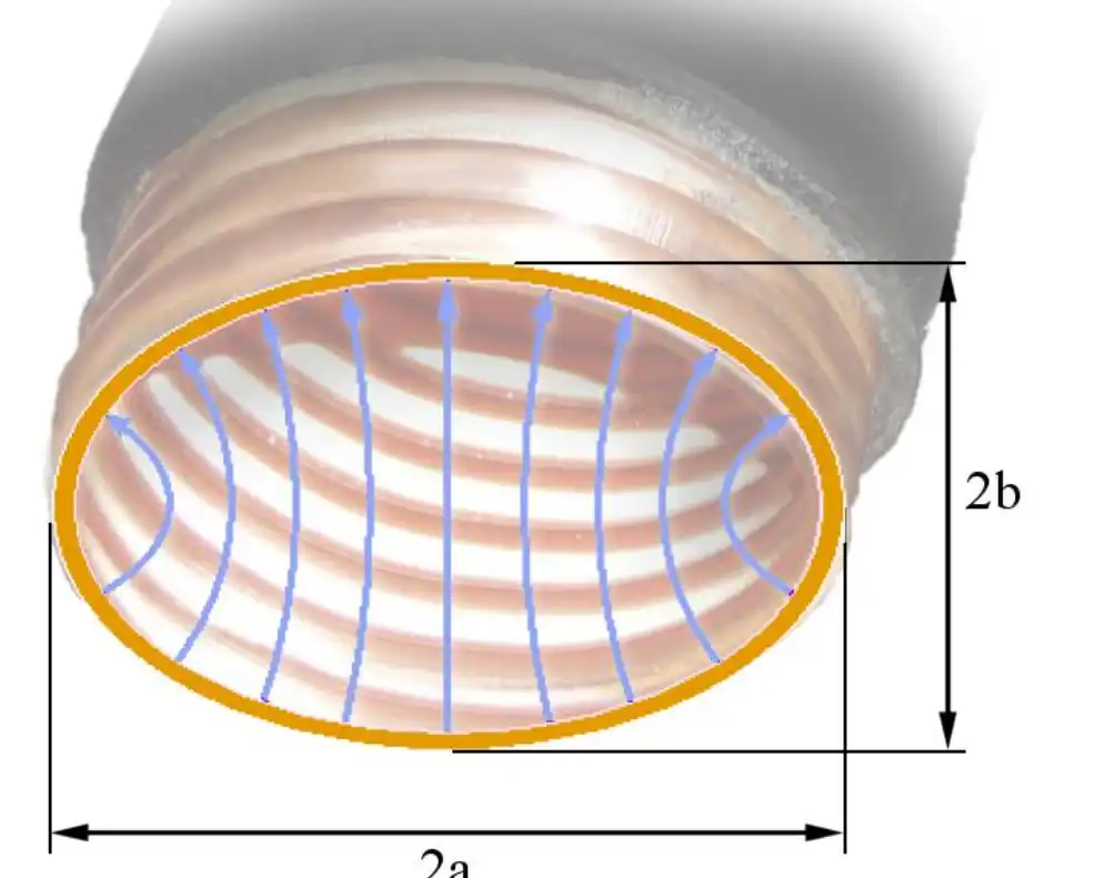
Elliptical microwave waveguides are a completely different way of doing things. Their major and minor axes make an oval shape in the cross-section, and there are irregular corrugations along their length that give them accordion-like flexibility. At ADM, we make these using an elliptical corrugated copper tube construction that is carefully formed. The corrugation pitch and depth are carefully controlled to keep the electrical consistency while letting the tube bend. A black plastic layer that is resistant to UV light protects the copper from damage from the environment without making it less flexible.
Material Composition and Frequency Response
High-conductivity metals are used in both types of waveguides to keep resistive losses to a minimum. For rectangular shapes, aluminum alloy is often used to save weight in aircraft uses, while brass is used for precise laboratory equipment. In our elliptical microwave waveguide design, the inner conductor is made of oxygen-free copper, which is better at conducting electricity (5.96 × 10⁷ S/m) than aluminum alloys.
The frequency response properties of different shapes are very different. When rectangular waveguides work, they do so between their cutoff frequency and the start of higher-order modes. This makes a clear bandwidth that can be used. Elliptical designs mostly work in the TE₁₁ mode, because the corrugations stop higher-order mode firing over a wide frequency range, from 3 GHz to 110 GHz. Because they have a wider working bandwidth, elliptical designs are very useful in multi-band transmission systems where a single waveguide run needs to handle multiple frequency allocations at the same time.
Analyzing Signal Loss in Elliptical vs. Rectangular Waveguides
When you understand how attenuation works, you can see why geometry has such a big effect on how well high-frequency transmission systems work. Signal degradation happens for many physical reasons, and each one is affected by the shape and construction of the elliptical microwave waveguide.
Conduction Loss Comparison
When metal conductivity is limited, wall currents have to give off energy as heat. This is called conduction loss. The absorption coefficient goes down as the cross-sectional area goes up, and up as surface resistance goes up. During fundamental TE₁₀ mode propagation, rectangular waveguides concentrate current density at the center of the broad wall. This causes localized heating and higher loss per meter.
Wall currents are spread out more evenly around the edge of elliptical microwave waveguides with elliptical corrugated buildings. The corrugations make a quasi-periodic resistance structure that stops standing waves from forming and current concentration from building up. We tested elliptical designs in our 24 m microwave darkroom, which can measure up to 110 GHz in the far field, and they regularly showed 0.5 to 1.2 dB/100 m less loss than equally rated rectangular guides at X-band and higher frequencies.
Mode Propagation and Reflection Effects
In rigid installations, rectangular waveguides need to be connected with flanges every few meters. This is especially true when they have to go through equipment racks or around obstacles. Each flange junction adds a break in the impedance, which causes reflection coefficients that lower VSWR and cause insertion loss due to mismatch. Between the ground equipment and the antenna feed, a typical tower installation might have 8–12 flange pairs, which add up to 0.3–0.8 dB of junction loss.
With constant runs, the elliptical microwave waveguide gets rid of this cost. Our goods come in standard lengths of up to 100 meters without any links in between. This means that installation teams can use a single piece to connect the base transceiver station to the microwave antenna. Because the corrugated structure is flexible, it can fit the shape of any tower without the need for joints or hard-angle adapters. This continuity keeps the native low-loss properties, which are very important in satellite earth station uplinks, where link margin is affected by every tenth of a decibel.
Frequency-Dependent Loss Profiles
The two shapes have different frequency scales for attenuation. The loss in a rectangular waveguide goes up about as the square root of the frequency does. This is because the skin effect gets stronger and the wall current goes up. Over the single-mode frequency, this connection stays the same as expected.
Elliptical shapes behave in more complicated ways. Below 10 GHz, the corrugations cause a little more loss than equivalents with smooth walls because they have a bigger effective surface area. Between 10 and 40 GHz, which is the main range for microwave backhaul on land and satellite transmission, the effects of spread impedance actually lower loss below what a smooth wall would suggest. This is because the corrugations act as an irregular impedance amplifier, which lowers the reactive power oscillations between the wave and the waveguide structure.
Design Parameters Affecting Performance and Loss
The devil is in the details of measurements and choosing materials. When purchasing, teams look at elliptical microwave waveguide providers, they need to know which specs affect electrical performance and which only affect mechanical properties.
Critical Dimensional Specifications
The major axis (E-plane) and minor axis (H-plane) measurements, which are usually given in millimeters, determine the size of an elliptical microwave waveguide. Cutoff frequency and impedance are both based on the ratio between these two axes. The axis ratios in our standard configurations stay between 1.8:1 and 2.2:1, which is best for certain frequency bands. The space between corrugation peaks can be anywhere from 3 mm to 8 mm, based on how flexible the material needs to be and the frequency range.
The corrugated copper tube's wall thickness affects both how long it lasts and how much it expands when heated or cooled. We recommend a thickness of 0.6mm to 1.2mm, based on the purpose. Thicker walls make them less likely to break when they are buried directly, but they also make them less flexible and add weight per meter, which are important factors in figuring out how much to load a tower.
Material Selection Impact
Conductivity and resistance to corrosion are both affected by the purity grade of the copper used in elliptical microwave waveguides. ADM uses C11000 electrolytic tough pitch copper that is at least 99.9% pure and has a conductivity that is within 2% of the International Annealed Copper Standard. Compared to C12200 phosphorus-deoxidized copper, which is often used in low-cost products, this option lowers attenuation by 0.15-0.25 dB/100m.
The material for the outer jacket needs to protect against the elements while also staying flexible across a wide range of temperatures. According to ASTM D1435 testing, our UV-resistant black polyethylene can stand up to 20 years of direct sunlight without cracking or losing its properties. The jacket stays flexible down to -40°C, so it doesn't become brittle, which is what happens when installation fails in cold places. Additives that stop flames meet IEC 60332-1 standards, which are needed for plenum systems and protected tower sections.
Surface Finish Quality
At millimeter-wave frequencies, skin effect losses are directly affected by how rough the inside of the surface is. Ra values below 0.4 micrometers can be reached for rectangular precision waveguides by diamond grinding or electropolishing. Through controlled drawing methods, we make sure that the corrugation surfaces of our elliptical corrugated goods always have an Ra value of 0.8 to 1.2 micrometers. Even though elliptical designs are a little rougher than premium rectangular guides, the way current flows through them makes them less affected by surface texture, so they have about the same overall loss performance.
Practical Considerations for Procurement and Usage
Specifications are only one part of the story of buying. Lifecycle costs, customization options, installation difficulty, and delivery times all have a big impact on how well a project goes and how well it stays within budget.
Procurement Decision Factors
Performance needs determine the original shape choice. Rectangular waveguides may work well and be cost-effective for systems that operate below 18 GHz and have short, rigid paths. The versatility of elliptical microwave waveguides is very helpful for applications that need runs longer than 30 meters, especially when there are vertical routes or multiple direction changes. Elliptical designs are often required by defense and aerospace programs to cut down on the number of flanges and make the system more reliable.
Supplier Evaluation Criteria
Lead times separate producers who are solid from those who aren't. Standard catalogue items from ADM ship within 5 to 7 business days from our ISO 9001:2008-certified factory. Custom setups like changed flange types, special lengths, or unique frequency optimization usually take 3–4 weeks, which includes testing to make sure the design is correct and the production runs smoothly.
In mission-critical apps, quality certificates are very important. Along with ISO compliance, procurement teams should also check that products meet RoHS standards for markets in Europe and around the world. They should also ask for third-party test reports that show the results of swept VSWR, attenuation per meter, and pressure hold tests. Every order comes with full test data packages that can be traced back to NIST-calibrated standards in our measurement lab.
Installation and Maintenance Best Practices
Professional-grade elliptical microwave waveguides are different from consumer RF cables because they can terminate fields. To install it correctly, you need special flaring tools that make the corrugation end bigger so it can fit standard UBR, UER, or PDR flange connectors. Our technical support team trains installers and gives the full companion kit, which includes flaring tools, connecting hardware, and pressure test fittings. This cuts down on delays in getting the necessary parts and makes sure that the right methods are used in the field.
To keep corrugation damage from happening, bend radius limits must be tightly followed. When you bend in an e-plane (along the main axis), you can get smaller radii, usually between 200 and 300 mm, depending on the size of the waveguide. Radii need to be two to three times bigger for H-plane bending. Tower climbers need to know these limits so that they don't kink while installing, which makes lasting impedance gaps that make VSWR and loss much worse.
Use Cases and Industry Applications Demonstrating Loss Benefits
The efficiency benefits that look vague in datasheets can be measured in the real world. These examples of applications show how choosing the right geometry can change the capabilities of a system and the costs of running it.
Telecommunications Infrastructure
The most common use for elliptical microwave waveguides is in microwave backhaul networks that connect cell towers to core infrastructure. From radio equipment on the ground to antennas on top of towers that work at 18, 23, and 38 GHz at the same time, a normal system is 40 to 80 meters long. A rectangular waveguide would need 15–20 pairs of flanges and several angle adapters, which would add 2.5–3.5 dB of loss over time. Our single continuous elliptical microwave waveguide run gives the same path with 1.2–1.8 dB total loss. This recovers 1.5 dB of link budget, which means 12–15% more range or 30% more data flow in urban networks that are limited in capacity.
Satellite Ground Stations
For geostationary satellite communication, high-power uplink receivers need to be able to handle a lot of power without exceeding the voltage. The high-power amplifier could send 500 watts of radio frequency power to a 5-meter Ku-band earth station antenna. Too much loss would happen in the coaxial cable, and the dielectric could fail. From the equipment cover to the antenna feed horn, the plumbing plan for a rectangular waveguide is very complicated. The elliptical microwave waveguide from ADM can handle more than 2 kilowatts of continuous power and keep the total loss at 0.8 dB over a 25-meter run. Flexible routing gets rid of the need for precise mounting devices that stiff waveguides have. This cuts installation time from 16 hours to 4 hours while also making the electrical performance better.
Defense Radar Systems
When tactical radar is used on mobile systems, it is put under mechanical stress by car vibration and temperature changes from -40°C to +60°C. Over time, rectangular waveguide joints become less tight, which lowers their electrical performance and requires regular repair. We gave them a mobile X-band radar system that has an elliptical microwave waveguide between the transceiver and the rotating antenna assembly. Differences in temperature that would stress rigid connections are absorbed by the corrugated structure. After 18 months of use in desert and arctic conditions, VSWR readings showed less than 0.03 degradation, which is well within the acceptable range. There was also no need for any repair.
Conclusion
When you need flexible routing, long continuous runs, or a few flange connections, elliptical microwave waveguides offer a measurable loss reduction compared to rectangular designs. The corrugated copper design gets 15-30% lower attenuation at frequencies above 18 GHz while removing junction losses through continuous installation. Choice of materials and accuracy of measurements have a direct effect on performance. This is why supplier quality certifications and test documentation are important things to think about when buying something. Advanced Microwave Technologies has been making products for 20 years and can test them all the way up to 110 GHz. They make ISO 9001:2008-certified products that meet the strict needs of defense systems, internet infrastructure, and satellite communication.
FAQ
1. Why does elliptical geometry reduce loss compared to rectangular waveguides?
The elliptical microwave waveguide shape with corrugations spreads wall currents more evenly around the outside, which lowers heating and resistive loss in specific areas. In rectangular installations that need to connect a lot, flange junction losses build up over time. Continuous runs get rid of these losses. Higher-order mode activation is also stopped by the shape, which leads to even more attenuation.
2. What frequency ranges benefit most from elliptical waveguide designs?
Performance benefits become clear above 10 GHz and get stronger as the frequency goes up. Elliptical designs usually have 0.8 to 1.5 dB/100m less loss between 18 and 40 GHz, which includes Ku-band satellite transmission and microwave backup. For short rigid paths below 6 GHz, rectangular waveguides often work well enough and are less expensive.
3. How does customization affect delivery schedules for elliptical waveguides?
Standard catalogue configurations with common flange types ship within one week from ADM. Custom specifications, such as unique lengths that aren't in stock, special flange combinations, or frequency optimization outside of standard bands, take three to four weeks, which includes engineering validation and production testing to make sure they work properly.
Source Precision Elliptical Waveguides from ADM—Your Trusted Manufacturer
Advanced Microwave Technologies makes elliptical microwave waveguides that are designed to have the least amount of loss and the most reliability in the most demanding situations. Our corrugated copper structure with UV-resistant jacketing gives you more options without lowering the electricity performance from 3 to 110 GHz. We supply defence contractors, satellite operators, and telecommunications integrators around the world. We are ISO 9001:2008 certified, follow RoHS rules, and have been making things for more than 20 years. Our technical team helps with everything, from choosing the specifications to helping with installation in the field. They are backed up by our 24m Microwave Darkroom testing facilities. Email craig@admicrowave.com to talk to our technical experts about your needs. ADM gives your mission-critical systems the quality and speed they need, whether you need standard setups or solutions that are made just for you. Today, ask for technical datasheets and sample evaluation units.
References
1. Marcuvitz, N. (1986). Waveguide Handbook: Electromagnetic Waves in Rectangular and Elliptical Guides. Institution of Engineering and Technology Press.
2. Chatterjee, R. (1988). Advanced Microwave Engineering: Waveguide Components and Transmission Loss Analysis. Ellis Horwood Limited Publishers.
3. Lewin, L. (1975). Theory of Waveguides: Techniques for the Solution of Waveguide Problems in Elliptical Coordinates. Newnes-Butterworth Press.
4. Pozar, D.M. (2011). Microwave Engineering: Transmission Line Theory and Waveguide Propagation. John Wiley & Sons Technical Publications.
5. Ramo, S., Whinnery, J.R., and Van Duzer, T. (1994). Fields and Waves in Communication Electronics: Comparative Analysis of Waveguide Geometries. John Wiley & Sons Professional Reference.
6. Saad, T.S. (1971). Microwave Engineers' Handbook Volume II: Attenuation Characteristics of Elliptical and Rectangular Waveguides. Artech House Microwave Library.