Does Conical Tapering Improve Termination Waveguide Return Loss?
Conical tapering significantly improves termination waveguide return loss performance by creating a gradual impedance transition that minimizes reflected energy. Unlike abrupt or stepped terminations, conically tapered designs smooth the electromagnetic path from the waveguide to the absorbing material, reducing standing wave ratios and enhancing signal integrity. This design approach addresses a critical challenge in high-frequency RF systems: managing impedance mismatches that generate reflections, which can damage sensitive amplifiers and degrade overall system performance. For procurement engineers and technical teams sourcing waveguide components for radar, satellite communication, and aerospace applications, understanding the quantifiable advantages of conical tapering provides a foundation for selecting optimized termination solutions that balance performance, reliability, and cost-effectiveness.
Understanding Return Loss in Termination Waveguides
Return loss is a measurement in decibels of how much power is sent back toward the source from the end of a waveguide. It works better when the return loss value is higher, because less energy is reflected and more is received or lost. This measure has a direct effect on signal quality, noise floor, and the lifespan of transmission parts, especially high-power amplifiers that can be damaged by retro-reflection.
Defining Return Loss and Measurement Standards
The Voltage Standing Wave Ratio (VSWR) is mathematically linked to return loss. Precision-grade terminations usually have VSWR values below 1.05:1, which means that return loss is more than 30 dB. Measurement methods use calibrated vector network analyzers that work within certain frequency bands. This makes sure that the results are always the same in a lab setting. Tough rules on return loss keep expensive magnetrons, klystrons, and traveling wave tube amplifiers from breaking down completely because of mirrored power in defense and satellite systems that need to work perfectly.
Common Termination Waveguide Types
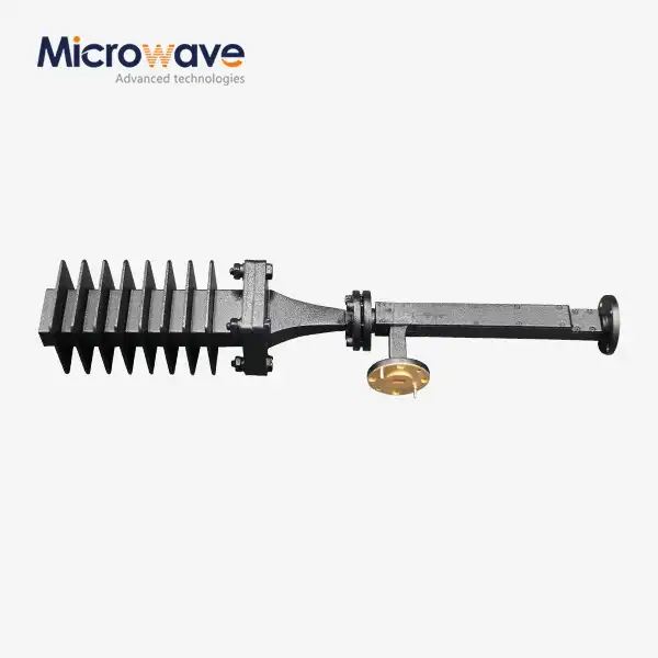
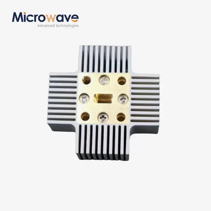
Different ending designs are used for different things. Standard flat terminations have simple material that absorbs waves and is fixed perpendicular to the path of the waves. These terminations are good for low-power instruments. Matched loads are made up of resistive materials that were carefully chosen to match the characteristic impedance of the waveguide. Using convective fins or liquid cooling jackets, dummy loads can handle higher power levels by better managing heat. Conically tapered terminations are an advanced method that uses geometric tapering to achieve better impedance matching over a wide frequency range. This makes them very useful in radar and wideband transmission systems.
Factors Influencing Return Loss Performance
The choice of material has a big impact on how well it absorbs energy and how much power it can handle. Different types of carbon-impregnated ceramics, silicon carbide, and specialized ferrites have different thermal and loss tangent properties. If the geometric design isn't done right, impedance discontinuities can happen in the transition area between the waveguide and the absorber. When thinking about frequency, it's important to remember that waveguide cutoff features and material properties change across operating bands. Impedance matching methods, such as tapering, directly deal with these issues by making slow changes that lower reflections across the whole frequency range that is important.
The Role of Conical Tapering in Waveguide Design
Conical tapering changes the way waveguide terminations are made by replacing sudden changes in impedance with smooth, gradual changes that send electromagnetic energy into materials that can receive it with little reflection. Better performance than flat or stepped forms, this geometric method uses basic wave propagation principles to get better results.
Electromagnetic Theory Behind Tapering Effectiveness
When electromagnetic waves hit places with changes in impedance, they reflect in part at each interface. By spreading the impedance change over a longer distance, conical narrowing lowers these reflections. This lets waves gradually adapt to changing transmission conditions. The taper works as a constant impedance transformer, preventing standing waves and lowering peak electric field levels that can damage voltage in high-power situations. Computer models of electromagnetic waves show that properly designed tapers can improve return loss by 5 to 10 dB compared to designs that don't have tapers, and this is true across all working bandwidths.
Critical Design Parameters
The rate of resistance change is based on the taper angle. Shallower angles usually give better performance at the cost of longer length. Most of the time, the best angles are between 5 and 15 degrees, which is a balance between electrical performance and system integration room needs. For smooth changes, the taper length must be long enough compared to the wavelength, which is usually several wavelengths at the lowest working frequency. To match the waveguide dimensions at the input and make a smooth transition to the absorbing section, the aperture sizes at both ends need to be carefully controlled. Engineers can use advanced modeling tools to find the best values for these parameters for certain frequency ranges and power levels.
Integration Challenges and Solutions
Adding conically tapered terminations to termination waveguide systems that are already in place can be hard from a mechanical and an electromagnetic point of view. Because of limited room, the length of the taper may be limited, forcing engineers to make trade-offs between best electrical performance and realistic limits. Flange compatibility makes sure that the mechanical link works well and that the electromagnetic flow stays the same with the current waveguide infrastructure. When using a lot of power, thermal management is very important because large areas that receive heat need to get rid of it quickly without damaging the structure. Precision CNC machining and additive manufacturing are two modern methods of making things that make it possible to make custom designs that solve these integration problems while still keeping the tight tolerances that are needed for reliable performance.
Performance Comparison: Conical Tapered vs. Other Termination Waveguides
Tests and simulations regularly show that conically tapered terminations perform better across a number of measures that are important for making procurement decisions. Knowing these differences helps technical buyers decide whether advanced termination designs are worth the extra cost compared to more traditional options.
Return Loss Performance Across Frequency Bands
When used in X-band applications between 8 and 12 GHz, conically tapered terminations often get VSWR values below 1.05:1, which means they have return loss over 32 dB across the whole band. When you compare flat terminations in the same frequency bands, you usually get VSWR values between 1.10:1 and 1.15:1, which means a return loss of 20 to 26 dB. This 6–10 dB improvement means that a lot less power is being reflected, which is very important for keeping solid-state power amplifiers in radar and communication systems safe. Similar performance benefits can be seen in the Ku-band (12-18 GHz) and higher frequency bands, where conical tapering keeps impedance matching stable even though it is more sensitive to differences in size.
Additional Performance Benefits
In addition to better return loss, conically tapered shapes offer better noise reduction by reducing the interactions between standing waves that cause false signals. Spreading power loss over larger areas that absorb it leads to better thermal management by lowering peak temperatures and increasing the lifetime of components. Lower peak electric field levels in the taper make it possible to handle more power. This is because there is less chance of voltage breakdown or arcing, which can slow down performance in high-power uses. Because of these benefits, conical tapering is a great choice for satellite ground stations that need to make sure their systems are always online and their signals are clear.
Material and Manufacturing Quality Factors
No matter what the geometric shape is, the choice of material has a big effect on efficiency. Copper structure is the best for heat transfer and transmission, but it costs more and is heavier. Aluminum has a good strength-to-weight ratio for aircraft uses where a little less mass is worth a little less efficiency. Plated metals find a balance between price and performance by using less base metal and making the surface more conductive. The quality of the surface finish has a direct effect on how well it works at high frequencies. Roughness causes resistance losses and worsens return loss at millimeter-wave frequencies. How closely production units match ideal performance is based on how precise the manufacturing tolerances are. Modern quality control and CNC cutting make it possible to get consistent results that meet strict requirements.
Selecting and Installing Conical Tapered Termination Waveguides
To pick the right waveguide terminations, you have to balance the need for high technical performance with limited budgets and tight delivery times. A methodical approach makes sure that the best components are chosen based on the needs of the application and the way the company buys things.
Technical Selection Criteria
The main requirement is frequency range compatibility, which ensures that the termination covers all operational bands with enough room to spare. The power rating must be higher than the maximum output of the emitter by the right amount to ensure safety. For continuous-wave uses, this is usually 1.25x, and for pulsed systems, it's higher multipliers that take into account peak power. Extreme temperatures, dampness, and vibrations in the environment can affect the choice of materials and the strength of the mechanical design. Specifications for return loss rely on how sensitive the system is. For example, tighter tolerances are needed for precision measurement uses than for general-purpose data links. By comparing these factors with conical tapered offerings, dummy loads, or standard matched loads, it becomes clear which architecture best meets the needs of a given application.
Installation Best Practices
When installed correctly, efficiency is maximized, and typical failure modes are avoided. Some mechanical things to think about are the tightening requirements for flange nuts, making sure that pressure is spread evenly, and making sure that electromagnetic continuity doesn't damage the sealing surfaces. Accurate alignment keeps the coaxial position, which stops mode conversion and reflection caused by mechanical discontinuities. In high-power installations, where temperature changes can put stress on rigid connections, thermal expansion accommodation is important. Protocols for grounding and bonding stop unwanted currents that slow down system performance. By following the manufacturer's instructions and industry norms, setups will work as planned and won't fail early, which would lower the reliability of the system.
Supplier Evaluation Factors
Purchasing managers should look at possible sources for termination waveguide in more than one way, not just the price per unit. If a seller can provide customized solutions that meet specific system needs, such as specialized flanges, non-standard frequency ranges, or built-in cooling features, it depends on their OEM capabilities and customization options. Lead times and production capacity affect project schedules. Well-known manufacturers keep common configurations in stock and offer reasonable lead times for custom production. Minimum order amounts make it harder to change how you buy things, especially for developing prototypes or making small runs. Quality technical support, such as application engineering before the sale and troubleshooting help after delivery, adds value beyond the physical part. Certification and compliance paperwork, like ISO 9001 quality management and RoHS environmental compliance, meet the needs of institutions buying things and make sure that the supply chain can be tracked.
Future Trends and Recommendations for B2B Procurement Managers
The waveguide termination business is always changing because of new technologies and shifting consumer tastes. Forward-thinking buying strategies put companies in a position to use new skills and manage risk in global supply lines that are very complicated.
Emerging Manufacturing Technologies
With additive manufacturing, complex shapes that were hard or impossible to make with traditional machining can be made possible. For example, improved taper curves and built-in cooling channels improve performance while lowering production costs. New materials, like ceramic composites and designed absorbers, can handle more power and stay stable at higher temperatures, which means they can be used in tough settings. As technologies get better and production volumes rise, these new ideas should lead to better performance and lower costs. This will help early adopters who are willing to test out new sources and methods.
Smart Monitoring Integration
Putting sensors inside waveguide terminations makes it possible to track performance in real time and plan ahead for maintenance needs. Temperature sensors detect unusual temperature situations that mean too much reflected power or cooling system breakdowns before they do a lot of damage. Return loss tracking through directional coupler integration checks the performance all the time and finds patterns of degradation that call for replacement before they get worse. These features increase system uptime and lower running costs, especially in remote locations like satellite ground sites where regular inspection methods are hard to implement for upkeep.
Cost-Benefit Analysis Framework
To properly evaluate conically tapered terminations, you need to look at their total cost of ownership, which goes beyond the initial purchase price. Lifecycle savings often make up for higher prices because they lead to better performance, less system downtime, and longer emitter lifetimes. How much these benefits are worth depends on the individual application, such as how important the system is, how much it costs to maintain, and how easy it is to get new parts. Applications that need high dependability, like defense radar and satellite communication, usually get a good return on their investment from better parts. On the other hand, business applications that need to save money may be willing to give up some performance in exchange for cheaper options. Procurement teams should make evaluation frameworks that take these things into account and make sure they are in line with the company's priorities and risk tolerance.
Strategic Supplier Partnerships
Building long-term ties with skilled termination waveguide providers gives you more than just a competitive edge when you buy something one time. Technical teamwork during the system design stages ensures that the standards for each component match the needs of the application, which avoids having to go through expensive redesign processes. Priority production scheduling and inventory management help supply chains be responsive, which is important for keeping projects on schedule. Field service, technical training, and application troubleshooting are all types of after-sales support that add value to products throughout their entire lifecycles. Purchasing managers should look for providers with qualified engineering staff, measurement tools that can do VNA testing up to 110 GHz, and quality certifications that show the process is mature and there is a culture of ongoing growth.
Conclusion
It is clear that conical narrowing lowers termination waveguide return loss by using basic electromagnetic principles that keep echoes to a minimum over a wide frequency range. The performance benefits, such as better impedance matching, better power handling, and better thermal management, meet important needs in high-precision measurement, defense, aerospace, and satellite communication. When system requirements call for maximum reliability and signal integrity, procurement workers looking at waveguide components should think about conically curved designs. To find the best balance between technical performance, cost, and integration needs, you need to look at a supplier's full range of skills, customization options, and long-term support. As manufacturing technologies improve and smart monitoring tools come out, the value argument for optimized waveguide terminations keeps growing. Companies that build strategic partnerships with suppliers and use forward-looking buying strategies will benefit.
FAQ
How does conical tapering compare to traditional flat terminations in return loss reduction?
Across all operational bandwidths, conical tapering usually reduces return loss by 5 to 10 dB compared to flat terminations. When designs are flat, there are sudden changes in resistance that cause reflections. On the other hand, when designs are curved, waves slowly move into materials that absorb them, which reduces the number of standing waves. This difference means that the VSWR goes from about 1.10 to 1.15:1 for flat terminations to less than 1.05:1 for good tapered designs. This means that a lot less power is reflected, which can hurt sensitive amplifiers.
Are conically tapered terminations suitable across different frequency ranges and power levels?
When it comes to frequency ranges, tapered shapes work well from microwaves to millimeter waves, with the right taper lengths for each frequency range. Power handling ranges from milliwatt measurement loads to megawatt peak power levels, as long as the right materials are used and a cooling system is built in. Low-power units have small forms, while high-power ones have longer soaking areas with convective fins or liquid cooling jackets. Custom designs take into account the specific frequency, power, and environmental needs of each application.
What are typical lead times and customization options from waveguide termination suppliers?
Standard catalog items usually ship within two to four weeks from well-known makers who keep stock. Custom designs take between 6 and 12 weeks to make, based on how complicated they are and whether they need special flanges, non-standard frequency ranges, built-in cooling features, or different ways to place them. Prototyping services shorten the time it takes to make something, giving you test units in three to five weeks. Minimum order quantities vary by supplier and level of customization, ranging from pricing for a single prototype to discounts for large production runs. Early on in the project planning process, procurement managers should talk to providers to make sure that technology needs are met and deadlines are reasonable.
Partner with ADM for Superior Termination Waveguide Solutions
Advanced Microwave Technologies Co., Ltd. (ADM) has more than 20 years of experience developing and making high-precision termination waveguides and RF components that meet the strict needs of research, defense, aerospace, and satellite communication. Our engineering team uses advanced measuring tools, such as tests up to 110 GHz in our cutting-edge 24m microwave lab, to make sure that the conically tapered terminations we offer have the best return loss performance. As a top manufacturer of termination waveguides, we know how hard it is for procurement professionals to find the right balance between technical requirements, delivery times, and cost constraints every day. Our OEM services offer fully customized solutions that are made to fit the needs of your specific system. They are backed by ISO 9001 certification and full technical support, from the initial design consultation to troubleshooting after delivery. Email us at craig@admicrowave.com to talk about how our termination waveguide options can help your system work better and be more reliable.
References
1. Marcuvitz, N. (1951). Waveguide Handbook. MIT Radiation Laboratory Series, Volume 10. McGraw-Hill Book Company.
2. Pozar, D. M. (2011). Microwave Engineering, 4th Edition. John Wiley & Sons, Chapter 6: Microwave Resonators.
3. Collin, R. E. (1992). Foundations for Microwave Engineering, 2nd Edition. IEEE Press, Section 5.7: Waveguide Discontinuities and Modal Analysis.
4. Saad, T. S. (Ed.) (1971). Microwave Engineers' Handbook, Volume 1. Artech House, Chapter 8: Waveguide Components and Devices.
5. IEEE Standard 149-1979 (R2008). IEEE Standard Test Procedures for Antennas. Institute of Electrical and Electronics Engineers, Section on Impedance Measurements.
6. Rizzi, P. A. (1988). Microwave Engineering: Passive Circuits. Prentice Hall, Chapter 4: Waveguide Tapers and Transitions.