





Coaxial Variable Attenuator VSWR: Why Flatness Matters
When specifying RF components for mission-critical applications, the relationship between a coaxial variable attenuator and VSWR flatness directly impacts measurement accuracy and system reliability. VSWR (Voltage Standing Wave Ratio) serves as a diagnostic indicator of impedance matching quality throughout the signal path. Variable attenuators with poor VSWR flatness introduce unpredictable reflections that distort signal amplitude, compromise test repeatability, and degrade overall system performance—issues that defense contractors, satellite integrators, and precision measurement labs cannot afford.
Understanding VSWR and Its Impact on Coaxial Variable Attenuators
By measuring the difference between the highest and lowest voltages along the transmission line, VSWR figures out how well RF energy moves through a part. A VSWR of 1:1, which means there is no reflection, is what a perfect 50-ohm system has. VSWR values for real-world attenuators are usually between 1.2:1 and 1.5:1, but it's important to keep that ratio constant across the whole operational bandwidth.
The Physics Behind VSWR Fluctuations
When there are differences in impedance, standing waves are created that send power back to the source instead of to the load. When the amount of attenuation changes in coaxial variable attenuators, the internal resistance networks change how they are set up. This could change the impedance seen at the input and output ports. Every dB change in the attenuation setting can cause small changes in the complex impedance, which show up as VSWR ripple across frequency.
Signal Integrity Consequences
RF systems can fail in a number of ways when the VSWR is not flat. When energy is reflected, it raises the insertion loss above the attenuation number that was intended. This can throw off the calibration in automatic test equipment. Standing wave patterns make amplitude nulls and peaks that change with frequency. This means that measures of broadband are not accurate. High reflections also raise the noise floor and intermodulation distortion, which makes spectrum analyzers and receiver chains less dynamic.
Datasheet Interpretation Skills
The buying teams should carefully read the details that explain the difference between theoretical VSWR and VSWR flatness. At the edges of the band, a device with a VSWR rating of 1.3:1 might spike to 1.8:1, which would lead to a big measurement error. Reliable manufacturers offer swept VSWR plots that show performance across the entire frequency range at a number of different attenuation settings. This lets engineers make sure the parts are right before putting them together in phased array antennas or satellite ground station receivers.
Common Causes of VSWR Variations in Coaxial Variable Attenuators
When buying, workers look at suppliers; they can ask the right questions if they know what causes VSWR instability in the first place. Performance consistency is affected by how precisely things are made, what materials are used, and how stressful the work is.
Design Architecture and Component Precision
When resistive cards or vanes are used in continuously coaxial variable attenuators, they need to be precisely placed mechanically. The actuation mechanism's tolerance stacking makes the resistive element change its entry depth in a way that isn't consistent, which has a direct effect on resistance. Step attenuators that use PIN diode switching matrices need precise control over the diode junction capacitance and series resistance. Changes in these parameters cause VSWR spikes when the state changes.
Connector Interface Quality
Different types of connections, like SMA, N-type, and 2.92mm, cause changes in the resistance. The junction VSWR is affected by the depth of the center pin, the location of the dielectric support bead, and the engagement of the outer conductor. When connected to precise test equipment, cheap attenuators often have commercial-grade connections with less precise limits. This makes the VSWR worse. MIL-DTL-3933-compliant connectors keep better control of dimensions and stay flat even after hundreds of mating cycles.
Environmental and Mechanical Stress
When attenuators get hot during high-power operation, temperature factors of resistive materials cause the resistance to change. When substrates and resistive films don't expand and contract at the same rate, microcracks form that change how well the RF works. When used in aircraft, vibrations open up internal connections, which causes impedance to change from time to time. A case study from a company that makes satellite payloads showed that attenuators that met VSWR specs at room temperature degraded by 0.3:1 at the highest and lowest working temperatures. This meant that vendors had to do qualification testing in all of these conditions.
We've seen that attenuators that weren't properly tested for mechanical stress often break when they are put into rack-mount systems. This is because the repeated rounds of adjusting them wear out the internal springs and locking mechanisms. This fact of operations makes it clear why lifecycle testing data should be required in purchase requirements.
Why VSWR Flatness is Critical for B2B Procurement Decisions
The initial cost of a component is only one part of a buyer's decision. The total cost of ownership and the effect on system performance are also important. The flatness of the VSWR has a direct effect on both factors in ways that might not be clear until they are integrated or put into use in the field.
System Reliability and Measurement Accuracy
Calibration standards that can be tracked are needed for RF test systems. If coaxial variable attenuators have VSWR noise greater than ±0.2 dB across the band, there is more uncertainty in the measurement chain when it comes to standardization. A company that makes 5G base stations found that inconsistent attenuator VSWR led to false failures during receiver sensitivity tests, which meant that functional units were wrongly thrown out. The problem was caused by attenuators that had a good theoretical VSWR but bad flatness, which meant that the source had to be changed and the product had to be reworked.
Cost Implications of Component Failure
Attenuators that don't have great VSWR performance age faster because reflected power heats up resistance parts in specific places. Because of this thermal stress, resistance values are changed permanently, which makes both attenuation accuracy and impedance matching not meet specifications. Early mistakes in the field raise the cost of warranties, throw off production plans, and hurt relationships with customers. It costs a little more up front to specify stricter VSWR flatness standards during buying, but it saves money in the long run by avoiding costs related to returns and system downtime.
Datasheet Comparison Methodology
To make a good purchase, you need to compare VSWR specs along with insertion loss, power handling, and frequency flatness. When an attenuator advertises a maximum VSWR of 1.25:1, it may not be clear that this only applies at a certain reduction setting or in certain frequency parts. The request looked at VSWR data across the whole operating band at three different levels of attenuation: minimum, mid-range, and maximum. Find the peak-to-peak VSWR change to get an objective measure of flatness.
By understanding how these factors affect each other, purchasing teams can set the importance of technical factors based on how important the application is. Radar calibration systems need stricter VSWR flatness than regular lab attenuators, which is why high-performance units cost more.
Industry-Leading Solutions: Brands and Products With Superior VSWR Flatness
There are different kinds of coaxial variable attenuators on the market that are best for different budgets and levels of performance. It's easier to qualify vendors when you know which ones are good at VSWR control.
Well-known companies like Keysight Technologies make attenuators that change all the time and keep their VSWR values within 0.05:1 from DC to 18 GHz. The average VSWR is 1.15:1. Their 8495 series uses precisely machined resistive cards with their own impedance compensation, which makes them good for use in standards labs and for primary calibration. Pasternack sells step attenuators that have electromechanical switching and a VSWR flatness of 1.3:1 across both C-band and X-band. These are made for cost-conscious telecom test applications.
When it comes to high-power coaxial variable attenuators, where VSWR stability under thermal load is very important, Bird Technologies is the leader. Their 8200 line keeps a certain VSWR up to 200 watts of average power, which is good for testing and burning in transmitters. Maury Microwave makes the most accurate manual attenuators for calibration standards. Their VSWR specs can be traced back to NIST standards, and they have clear budgets for error.
When buying, professionals look at these options; they should ask for test data from a third party that proves VSWR success. Some sellers offer Monte Carlo analyses that show how VSWR varies across different production lots, which shows that they can control the manufacturing process. Custom engineering choices let you change the types of connectors, frequency bands, and attenuation ranges to fit the needs of a particular application. When working with experienced makers, you can often do this without having to wait a long time.
We suggest getting manufacturers involved early in the design process so that you can use their help with applications engineering. Suppliers who know a lot about radio frequency (RF) can suggest attenuator setups that will give you the best VSWR flatness for your system architecture. This will save you a lot of money in the long run on redesigns.
How to Ensure Optimal VSWR Flatness When Designing or Procuring Coaxial Variable Attenuators
To get reliable VSWR performance, you need to pay attention to system integration features that aren't covered by the attenuator standard. Design engineers and procurement teams both play a part in making things work by following strict procedures for choosing and checking things.
Impedance Matching Strategy
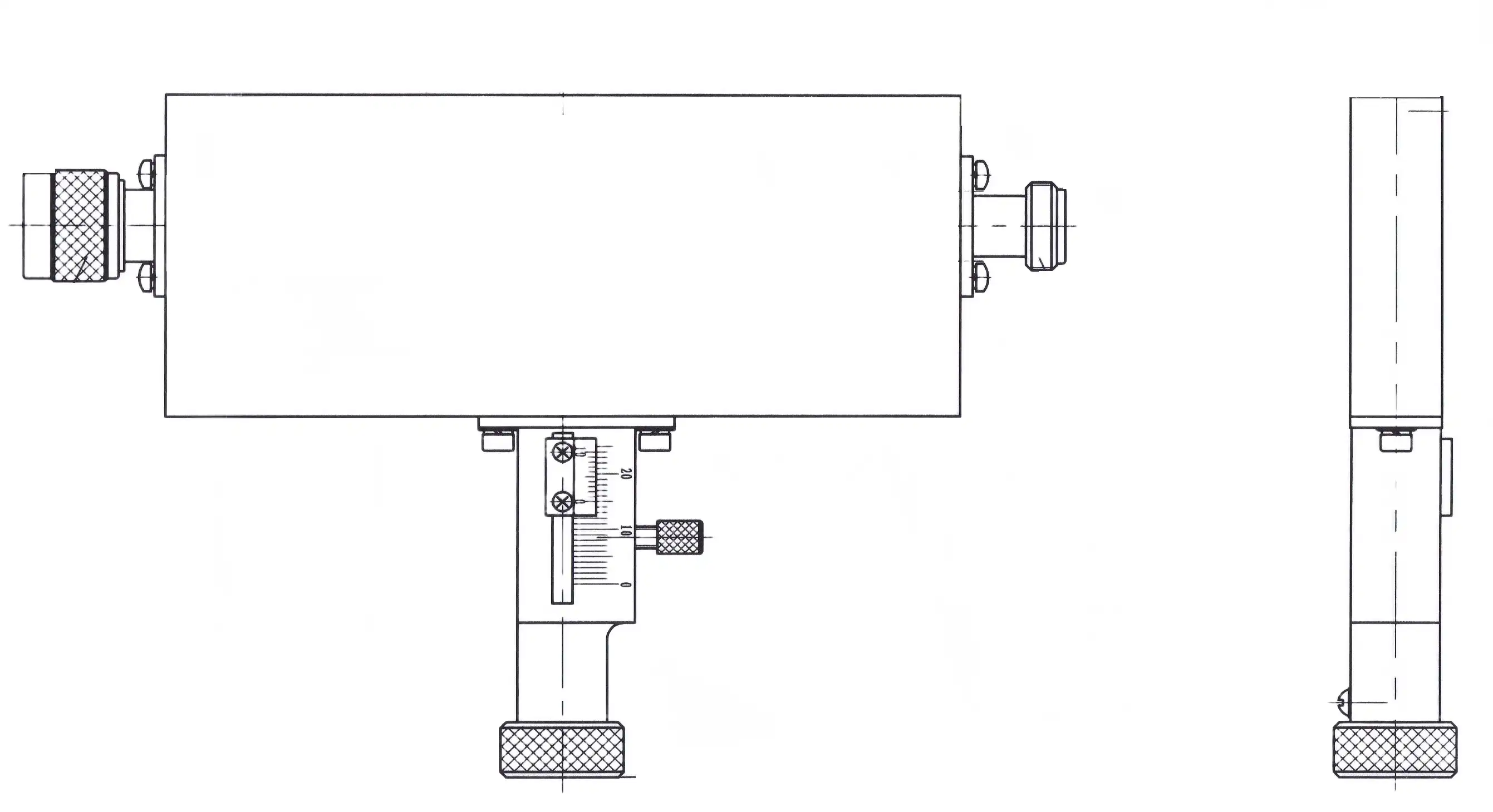
Systems that are made to work with a constant 50-ohm resistance should be able to handle coaxial variable attenuators. Time-domain reflectometry can be used to find impedance breaks at connector interfaces and cable assemblies next to the attenuator. Mismatches at changes are kept to a minimum with phase-matched wire assemblies. Coaxial-to-waveguide adapters must keep VSWR better than the attenuator standard when plugged into waveguide systems so that they don't hide the performance of the attenuator.
Connector and Cable Management
Use calibrated wrenches to apply the right torque: 8 inch-pounds for SMA connectors and 12 inch-pounds for N-type connectors. When you overtighten, the center wires and outer ferrules get deformed. This makes impedance bumps that lower VSWR. Before each mating, use magnification to check the connection surfaces for bent pins or other contamination. In order to clean, you should use lint-free brushes and dry isopropyl alcohol instead of compressed air, which can push particles into dielectric gaps.
Environmental Qualification Testing
Give an operational temperature range and ask for data that shows VSWR stability within that range. Vibration profiles should meet the conditions of the end use—10 G of sinusoidal sweep for airborne uses and 5 G of random vibration for mobile systems on the ground. Testing for humidity according to MIL-STD-810 shows ways for water to get in, which break down the dielectric properties and make the VSWR drift over time.
Procurement Verification Checklist
Effective supplier qualification includes these essential elements:
- Ask for certificates of conformance that include measured VSWR data for the exact serial numbers that were shipped, not just average performance.
- Check that the test tools used for acceptance testing can be traced back to their setting.
- Need data showing that the difference in VSWR stays within the allowed ranges from one lot to the next during production runs.
- Set up protocols for incoming inspections that use calibrated vector network analyzers to test VSWR samples before installation.
- Talk about the warranty terms so that they cover VSWR degradation during the working life.
Procurement and engineering teams work together to make sure that specifications reflect the real needs of the application. Professionals in purchasing who know about the technical aspects of VSWR can deal well with sellers, while engineers make sure that the chosen parts meet the performance goals at the system level.
Conclusion
The VSWR flatness of coaxial variable attenuators directly affects the accuracy of RF system measurements, the durability of components, and the dependability of operations. When making purchases, companies should give more weight to providers who can show consistent VSWR control through tested data, strong production methods, and quick engineering help. By using strict selection criteria and testing procedures, companies make sure that the parts they use keep the integrity of signals even in high-stress defense, aerospace, satellite communication, and precision test situations where performance can't be compromised.
Frequently Asked Questions
How does VSWR flatness specifically affect RF testing accuracy in automated systems?
VSWR ripple across frequency makes measurements less accurate, and this problem gets worse as you go through the calibration chains. Automated test equipment needs steady reference levels. If the attenuator VSWR changes by more than 0.15:1 across the band, reflected power causes amplitude mistakes of more than ±0.5 dB. This uncertainty spreads to measurements of the device being tested, making good units fail the specification limits or bad units pass without being noticed.
What frequency range considerations matter most when selecting variable attenuators?
At higher frequencies, component parasitics become more important. When it comes to resistor film technologies, attenuators for 18 GHz bands are different from those for 40 GHz bands or millimeter-wave bands. Make sure that the VSWR flatness requirements are met across your whole operating span, not just at spot frequencies. Broadband attenuators aren't always as flat as band-specific designs that are made to work best with small frequency bands.
Can custom engineering improve VSWR performance for specialized applications?
Manufacturers who are very good at RF design can change the shapes of housings, connectors, and resistive networks to get the best VSWR for certain frequency bands and attenuation ranges. Usually, you have to place a minimum order quantity for custom solutions, but they work better when standard store goods don't. The investment pays off in high-volume production or performance-critical situations where system capabilities are limited by the capabilities of individual parts.
Partner With a Coaxial Variable Attenuator Supplier Committed to RF Excellence
Advanced Microwave Technologies Co., Ltd (ADM) delivers precision-engineered attenuators like the coaxial variable attenuator with verified VSWR flatness backed by over two decades of microwave component expertise. Our ISO 9001:2008-certified manufacturing processes and testing capabilities extending to 110 GHz ensure every unit meets stringent specifications for defense, aerospace, and satellite communication applications. We offer customized OEM solutions tailored to your exact impedance matching requirements, complete with full swept VSWR documentation and calibration traceability. Contact our engineering team at craig@admicrowave.com to discuss your procurement needs and receive detailed technical specifications that demonstrate our commitment to signal integrity and measurement accuracy.
References
1. Pozar, David M. "Microwave Engineering, Fourth Edition." John Wiley & Sons, 2011.
2. Agilent Technologies Application Note 1287-1. "Understanding the Fundamental Principles of Vector Network Analysis."
3. MIL-DTL-3933. "Detail Specification: Attenuators, Fixed and Variable, Coaxial and Waveguide."
4. IEEE Standard 287-2007. "IEEE Standard for Precision Coaxial Connectors at RF, Microwave and Millimeter-wave Frequencies."
5. Hewlett-Packard Application Note 154. "S-Parameter Design," Hewlett-Packard Company, 1972.
6. Rytting, Douglas K. "Network Analyzer Error Models and Calibration Methods." 54th ARFTG Conference White Paper, 1999.
YOU MAY LIKE
 VIEW MOREHigh Power Waveguide to Coaxial Adapter
 VIEW MOREMiter Bend Waveguide
 VIEW MORECircular Waveguide To Coaxial Adapter
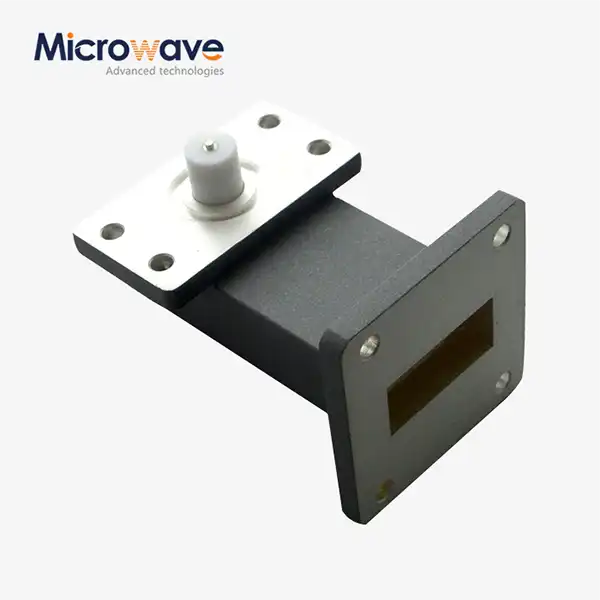 VIEW MORERight Angle Waveguide to Microstrip Adapter
 VIEW MOREWG Bandpass Filter
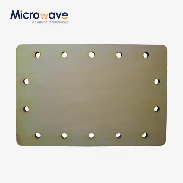 VIEW MOREWaveguide Short Plate
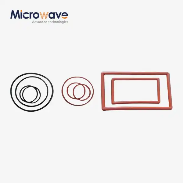 VIEW MOREWaveguide Flange Gasket
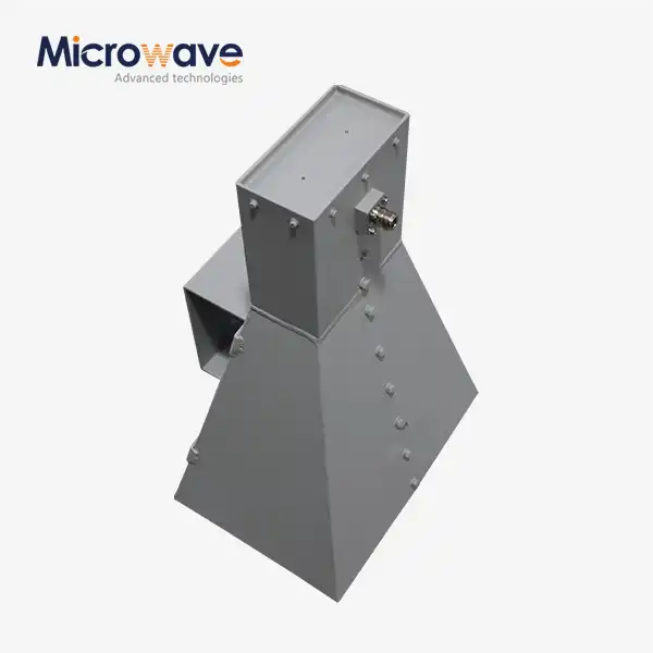 VIEW MOREWideband Double-ridged Horn Antenna
