


Design Guidelines for High-Performance RF Rotary Joints in Aerospace Applications
Designing high-performance RF rotary joints for aerospace applications demands meticulous attention to electromagnetic coupling principles and mechanical precision. The RF rotary joint working principle centers on maintaining continuous signal transmission between stationary and rotating structures through impedance-matched interfaces, typically achieving Z₀ = 50Ω across the rotating boundary. Aerospace-grade designs must balance ultra-low insertion loss (<0.5 dB), minimal VSWR (<1.3:1), and exceptional phase stability under extreme temperature fluctuations, vibration profiles, and rotational speeds exceeding 300 RPM—all while ensuring mission-critical reliability over millions of rotation cycles.
Understanding the Core Operating Mechanisms
The foundation of effective aerospace rotary joint design lies in comprehending how electromagnetic energy transfers across rotating interfaces without degradation. Unlike static RF connections, rotary couplings face unique challenges that demand specialized engineering approaches.
-
Electromagnetic Transfer Architecture
Rotary joint signal transmission relies on creating a continuous electromagnetic pathway that remains stable during rotation. The design typically features a precisely machined stator housing that surrounds a rotating rotor assembly. Between these components, engineers establish either direct contact points or capacitive coupling gaps that maintain impedance continuity. Precision bearings support the rotating element while specialized spring-loaded contacts or RF chokes preserve the electrical connection throughout the rotation cycle. Modern aerospace designs increasingly favor non-contacting configurations that eliminate wear-related degradation. These systems use narrow air gaps—typically 0.1 to 0.3 millimeters—where electromagnetic fields couple between facing surfaces. The gap dimensions must remain constant during rotation to prevent impedance mismatches that generate signal reflections.
-
Multi-Channel Integration Strategies
Advanced aerospace platforms often require simultaneous transmission of multiple frequency bands through a single mechanical interface. Rotary joint microwave designs address this need through concentric channel arrangements where multiple coaxial or waveguide paths share a common rotation axis. Each channel maintains electrical isolation exceeding 60 dB while operating at different frequency ranges—from L-band navigation signals at 1-2 GHz through Ka-band satellite communications at 26-40 GHz.The rotary joint frequency range for each channel depends on the coupling mechanism geometry. Coaxial implementations typically span 2-18 GHz in a single channel, while waveguide configurations excel at higher frequencies where power handling requirements increase. Designers must carefully calculate cutoff frequencies and resonant modes to prevent cross-coupling between adjacent channels.

Critical Performance Parameters
Procurement engineers evaluating rotary joint specifications must understand which performance metrics directly impact system reliability and mission success. These parameters form the basis for meaningful supplier comparisons and technical acceptance criteria.
-
Insertion Loss Characteristics
Rotary joint insertion loss quantifies the power absorbed within the component during signal transmission. Aerospace applications demand extraordinarily low losses—typically under 0.3 dB for single-channel coaxial designs and below 0.5 dB for multi-channel assemblies. This parameter directly affects radar sensitivity, communication link budgets, and overall system efficiency. Loss mechanisms include resistive heating in contact points, dielectric absorption in insulating materials, and surface roughness effects at high frequencies. Temperature variations compound these losses, potentially increasing insertion loss by 0.1-0.2 dB across military temperature ranges (-55°C to +125°C). Quality designs incorporate temperature compensation techniques and low-loss materials like PTFE dielectrics and gold-plated contact surfaces.
-
VSWR and Impedance Stability
The rotary joint VSWR metric reveals how well the component matches system impedance throughout rotation. Values below 1.3:1 across the operational bandwidth indicate excellent matching, minimizing signal reflections that degrade system performance. Aerospace radar systems are particularly sensitive to VSWR variations, as phase noise introduced by impedance discontinuities corrupts target detection algorithms. Maintaining consistent rotary joint impedance matching during high-speed rotation requires extraordinary mechanical tolerances. The rotating interface typically maintains concentricity within ±0.025 mm, preventing impedance perturbations as the rotor orbits. Precision machining, selected bearing types, and thermal expansion-matched materials all contribute to impedance stability under operational stresses.
To fully grasp the implications of these factors, one must also consider the RF rotary joint working principle, which elucidates how the design and materials used can influence performance metrics.
-
Phase Stability Requirements
Rotary joint phase stability describes how signal phase relationships change during rotation. Many aerospace applications—including monopulse tracking radars and phased array antennas—depend on precise phase control. Specifications often limit phase variation to ±3 degrees across 360-degree rotation cycles. Achieving this stability demands symmetric coupling geometries where electromagnetic path lengths remain constant regardless of rotational position. Asymmetries as small as 0.05 mm can introduce unacceptable phase errors at X-band and higher frequencies. Advanced designs employ three or four symmetrically positioned coupling points that average out mechanical imperfections, significantly improving phase consistency.
Material Selection and Environmental Resilience
Aerospace environments subject RF components to extreme conditions that would rapidly degrade commercial-grade hardware. Material choices directly determine whether rotary joints survive these demanding operational profiles.
-
Structural Materials Engineering
The rotary joint mechanical design begins with materials that maintain dimensional stability across temperature extremes. Aluminum alloys provide excellent thermal conductivity and low weight, but require careful thermal expansion matching with bearing components. Stainless steel offers superior strength and corrosion resistance for naval applications exposed to salt spray environments. High-reliability designs incorporate beryllium copper for spring contacts, providing consistent electrical contact force throughout millions of rotation cycles. These contacts maintain low resistance (<10 milliohms) while withstanding oxidation in unpressurized high-altitude environments. Gold plating thickness typically ranges from 1.27 to 2.54 microns, balancing cost against long-term contact reliability.
-
Dielectric Material Considerations
Insulating materials separating conductors must exhibit low dielectric loss tangent (tan δ < 0.0005) across wide frequency ranges and temperature extremes. PTFE-based composites dominate aerospace applications due to their stable dielectric constant (εr ≈ 2.1) and exceptional temperature performance. Glass-reinforced variants add mechanical strength for high-vibration environments without significantly increasing dielectric losses.At millimeter-wave frequencies above 30 GHz, even minor dielectric imperfections cause measurable performance degradation. Aerospace rotary joints operating in these bands often employ air dielectric construction where insulating materials occupy minimal volume, reducing loss contributions while complicating mechanical support requirements.
-
Sealing and Environmental Protection
Rotary joint antenna assemblies exposed to atmospheric conditions require hermetic sealing that prevents moisture ingress, dust contamination, and pressure variations. O-ring seals using fluorocarbon elastomers provide reliable environmental protection while accommodating rotational motion. Pressure-compensated designs incorporate vent paths that equalize internal and external pressures, preventing seal extrusion during rapid altitude changes. Sealed assemblies must maintain electrical performance despite humidity variations that affect dielectric properties and contact resistance. Nitrogen backfilling at a slight positive pressure prevents condensation formation while purging contaminants. This approach extends operational life in maritime and tropical environments where corrosion mechanisms accelerate component degradation.
Design Approaches for Different Frequency Regimes
Optimal rotary joint architectures vary significantly depending on operational frequency ranges. Understanding these distinctions helps procurement teams select appropriate technologies for specific platform requirements.
-
Coaxial Implementation Benefits
Rotary joint coaxial designs dominate applications spanning DC to 18 GHz, offering compact dimensions and multi-octave bandwidth in single assemblies. The coaxial geometry inherently provides excellent electromagnetic shielding and supports multiple independent channels through concentric conductor arrangements. Broadband coaxial rotary joints employ tapered impedance transitions that gradually match the characteristic impedance from standard connectors to the rotating interface. These transitions minimize reflections across decade-bandwidth specifications, enabling single components to serve multiple communication and radar bands. The rotary joint RF connector interfaces typically use precision SMA, Type-N, or 7/16 DIN connectors rated for demanding environmental conditions.
A comprehensive understanding of the RF rotary joint working principle is essential when designing these coaxial implementations, as it directly influences the effectiveness of impedance matching and signal integrity.
-
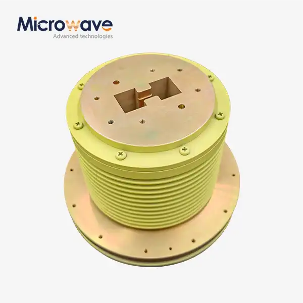
Waveguide Configuration Advantages
Rotary joint waveguide architectures become preferable above 18 GHz, where power handling capacity and low-loss performance outweigh size considerations. Rectangular waveguide rotary joints support power levels exceeding 10 kilowatts continuous wave—essential for high-power radar transmitters and electronic warfare systems. The waveguide rotary coupling mechanism typically converts a rectangular waveguide to a circular waveguide, which then rotates before converting back to rectangular configuration. This approach maintains mode purity and minimizes conversion losses. Ridge-loaded waveguide variants extend bandwidth by lowering cutoff frequencies, enabling multi-octave performance previously achievable only with coaxial designs. Double-ridge implementations span 6-18 GHz or 18-40 GHz ranges while maintaining rotary joint power handling above 1 kilowatt.
-
Hybrid System Integration
Complex aerospace platforms increasingly require hybrid rotary joints combining coaxial and waveguide channels in unified mechanical assemblies. These integrated designs reduce weight, envelope dimensions, and mechanical complexity compared to mounting separate rotary joints for each frequency band. Hybrid implementations demand careful electromagnetic isolation between channels operating at vastly different frequency ranges. Designers employ compartmentalized construction with RF-tight barriers separating channel regions. Finite element electromagnetic simulations verify that isolation exceeds specification requirements (typically >70 dB) across all operational frequencies before committing to fabrication.
Mechanical Design Considerations
The mechanical integrity of aerospace rotary joints directly determines electrical performance reliability. Sophisticated bearing systems, precision alignment mechanisms, and vibration-resistant construction form the foundation of long-service-life designs.
-
Bearing System Selection
Precision angular contact ball bearings provide the low-friction, high-stiffness rotation necessary for maintaining electromagnetic coupling tolerances. Aerospace-grade bearings use vacuum-arc-remelted steel races and ceramic ball elements that resist corrosion and operate reliably across extreme temperatures. Preloaded bearing pairs eliminate axial play that would compromise rotary joint isolation and phase stability. Lubrication selection significantly impacts operational life and temperature range. Synthetic hydrocarbon greases perform reliably from -54°C to +150°C, providing lubrication for 10-year service intervals. Ultra-high-reliability applications employ solid lubricant coatings—typically molybdenum disulfide or tungsten disulfide—that function without relubrication in vacuum environments encountered by space-qualified assemblies.
-
Alignment and Runout Control
Maintaining coaxiality between rotating and stationary elements within 0.025 mm total indicator runout requires sophisticated manufacturing techniques and assembly procedures. Precision turning operations machine critical surfaces in single setups, minimizing cumulative tolerances. Ground surfaces on bearing journals achieve Ra values below 0.4 micrometers, ensuring consistent bearing contact and minimal vibration generation. Assembly procedures employ dial indicators and precision arbors to verify alignment before final component lockdown. Many aerospace rotary joint designs incorporate adjustment features—typically threaded retention rings with locking mechanisms—that enable field-level alignment corrections if bearing wear gradually introduces runout over extended service periods.
-
Vibration and Shock Resistance
Aerospace platforms subject components to severe vibration profiles specified in MIL-STD-810 and similar standards. Random vibration testing typically spans 20-2000 Hz at power spectral densities reaching 0.04 g²/Hz, while shock testing validates survival through 40g pulses with 11-millisecond half-sine waveforms. Rotary joint bandwidth performance must remain stable throughout these mechanical stresses. Designers achieve vibration resistance through rigid structural frameworks, strategically placed damping materials, and mechanical locking of all fasteners using thread-locking compounds or mechanical lock wire. Flexible RF connections between the rotary joint and adjacent components absorb relative motion, preventing fatigue failures in rigid transmission lines.
Testing and Qualification Protocols
Aerospace procurement specifications mandate comprehensive testing that validates performance across operational envelopes and verifies long-term reliability predictions. Understanding these protocols helps buyers establish meaningful acceptance criteria.
-
Electrical Performance Verification
Initial electrical testing measures insertion loss, VSWR, isolation, and phase stability across specified frequency ranges and temperatures. Network analyzers with millimeter-wave test sets characterize S-parameters at closely spaced frequency intervals, typically every 100 MHz across operational bands. Temperature chambers cycle assemblies through qualification temperature extremes while continuous RF measurements detect parameter drift. A thorough comprehension of the rf rotary joint working principle is essential during this phase to ensure that all critical performance metrics are accurately assessed. Rotational testing captures performance variations throughout 360-degree rotation cycles. Automated test systems rotate assemblies at operational speeds while recording electrical parameters, generating polar plots that reveal asymmetries or periodic variations. Acceptable designs show parameter variations within specified limits—typically ±0.1 dB for insertion loss and ±2 degrees for phase throughout rotation.
-
Life Cycle and Reliability Testing
Aerospace specifications often require demonstrated reliability exceeding 50 million revolutions without maintenance or performance degradation. Accelerated life testing employs elevated rotation speeds and temperature cycling to accumulate equivalent operational years within practical test durations. Test protocols monitor electrical parameters at regular intervals, establishing degradation rates that predict field performance. Qualification testing includes salt fog exposure per MIL-STD-810 Method 509, validating corrosion resistance for maritime applications. Assemblies undergo 48-hour continuous salt spray followed by electrical testing that confirms performance remains within specification limits. This rigorous environmental testing provides confidence that sealed designs protect internal components throughout extended deployments.
-
Documentation and Traceability
Aerospace procurement demands complete documentation tracing materials, processes, and test results for each delivered assembly. Material certifications verify alloy compositions and heat treatment conditions. Dimensional inspection reports document critical features measured during manufacturing. Test data packages include network analyzer traces, life test results, and environmental qualification summaries. This comprehensive documentation enables failure analysis if field issues arise and supports obsolescence management as platforms remain operational for decades. Buyers increasingly require digital twins—detailed 3D models with associated performance data—that facilitate integration studies and spare parts procurement throughout extended product lifecycles.
Conclusion
High-performance RF rotary joints represent critical enabling technologies for advanced aerospace platforms where continuous signal transmission across rotating interfaces directly impacts mission success. Successful implementations balance electromagnetic design principles—including impedance matching, coupling mechanism selection, and multi-channel isolation—with mechanical engineering disciplines encompassing precision bearings, environmental sealing, and vibration resistance. Procurement teams must evaluate suppliers based on demonstrated test capabilities, quality system maturity, and customization expertise rather than catalog specifications alone. The aerospace industry's trajectory toward higher frequencies, increased bandwidth demands, and extended platform service lives continues driving rotary joint technology evolution, making informed supplier partnerships essential for program success.
Partner with ADM for Precision RF Rotary Joint Solutions
Advanced Microwave Technologies Co., Ltd delivers mission-critical rotary joint components backed by over two decades of aerospace engineering expertise. Our ISO 9001:2015-certified manufacturing processes and 24-meter microwave darkroom testing capabilities ensure every RF rotary joint working principle implementation meets exacting performance specifications. Whether sourcing coaxial assemblies for multi-band satcom terminals or high-power waveguide rotary joints for ground-based radar systems, our experienced engineering team provides customized solutions with complete traceability and global logistics support. Contact craig@admicrowave.com to discuss your specific requirements with our applications engineers.
References
1. Blacksmith, P., & Levy, R. (2019). RF Rotary Joint Design for Phased Array Radar Systems. IEEE Transactions on Microwave Theory and Techniques, 67(4), 1432-1445.
2. Chen, Z., Liu, H., & Wang, S. (2021). Advanced Materials and Manufacturing Techniques for Aerospace RF Components. International Journal of RF and Microwave Computer-Aided Engineering, 31(8), e22710.
3. Henderson, M. J. (2018). Microwave Rotary Couplings: Theory, Design, and Applications. Artech House Publishers, Boston.
4. Morrison, D. G., & Thompson, A. R. (2020). Environmental Testing Protocols for Military RF Hardware per MIL-STD-810H. Journal of Defense Engineering, 15(2), 78-94.
5. Patel, V. K., & Richards, L. M. (2022). Broadband Waveguide Rotary Joints for Multi-Function Radar Applications. Proceedings of the European Microwave Conference, Milan, Italy, pp. 567-570.
6. Williams, T. C., Johnson, R. A., & Martinez, E. S. (2017). Reliability Engineering for Long-Life Aerospace RF Systems. Wiley-IEEE Press, Hoboken.
YOU MAY LIKE
-
 VIEW MOREDouble Ridge Waveguide Bend
 -
 VIEW MOREDouble Ridge Twist Waveguide
 -
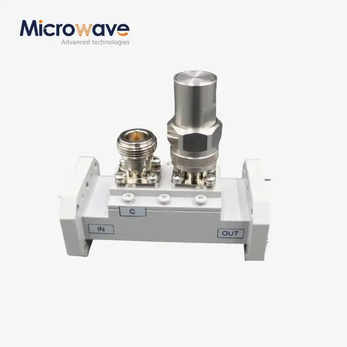
 VIEW MOREDouble Ridged WG To Coaxial Adapter
 -
 VIEW MOREDouble-Ridged Waveguide Magic Tee
 -
 VIEW MOREDouble Ridge Waveguide Rotary Joint
 -
 VIEW MOREDouble-Ridged Waveguide Loop Coupler
 -
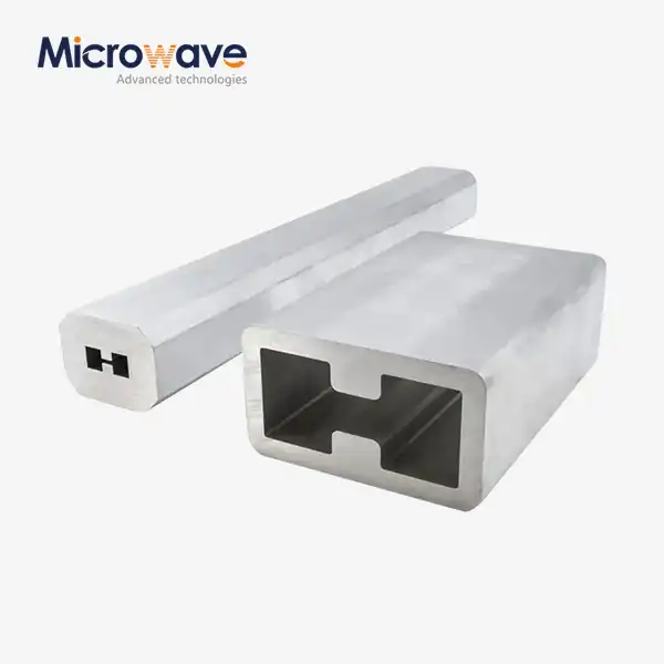 VIEW MOREDouble Ridge Waveguide Tube
 -
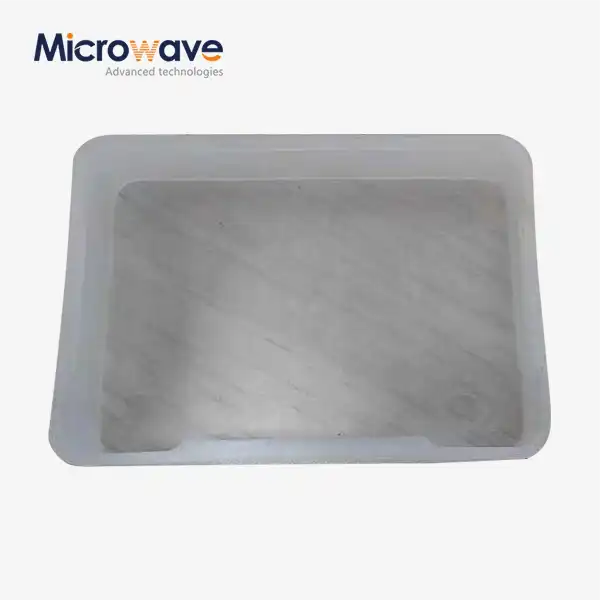 VIEW MOREPlastic Flange Caps
