Coaxial Bandpass Filter Insertion Loss — Cavity Q Factor Limits
Understanding the relationship between insertion loss and cavity Q factor in coaxial bandpass filters is essential when selecting RF components for mission-critical systems. Insertion loss measures the signal power reduction as it passes through the filter, directly impacting link budget and system efficiency. The cavity Q factor quantifies how efficiently the resonant structure stores electromagnetic energy relative to dissipation. Higher Q values correspond to sharper frequency selectivity and lower losses, making this parameter crucial for procurement engineers sourcing bandpass filters for defense radar, satellite ground stations, or cellular infrastructure where every tenth of a dB matters.
Fundamentals of Coaxial Bandpass Filters and Insertion Loss
Coaxial Bandpass Filters use the Transverse Electromagnetic (TEM) mode inside carefully machined metal holes to separate certain frequency bands while blocking signals that aren't needed. These distributed-element systems keep working well from UHF to Ka-band, while lumped-element forms break down quickly at microwave frequencies. They are often used in wireless base stations to separate send and receive routes, in aerospace data links that need to work without interference, and in radar systems that need steep roll-off features to get rid of clutter from nearby bands.
Operating Principles and Physical Construction
A coaxial resonator filter is made up of metal housings that are either round or square and hold center wires. These resonators connect electromagnetically through irises or probes, making a multi-pole reaction that determines the shape of the passband and the level of reduction in the stopband. The physical measurements determine the resonant frequency, and the space between the conductors determines the bandwidth. In manufacturing, housings are usually made of aluminium or brass and are plated with silver or gold to improve surface conductivity and lower skin-effect losses that lower the Q factor at microwave frequencies.
Insertion Loss Components and System Impact
There are three main ways that insertion loss happens. Conductor loss happens when RF currents hit metals with limited conductivity. This creates heat through resistive dissipation. Dielectric loss is caused by polarisation lag in any insulation materials that are present, but air-filled coaxial designs make this effect less noticeable. Radiation loss isn't very big in buildings that are properly protected, but it gets big if the sealing around the enclosure breaks down. When choosing filters for satellite transponders that work close to noise floors or long-distance microwave links that can't use a lot of power, an extra 0.3 dB of loss can cut the range by several kilometres or require expensive updates to the amplifiers.
The Cavity Q Factor Relationship
The empty Q factor of a coaxial bandpass filter measures how well a resonator stores energy by comparing the amount of energy it stores to the amount it loses each cycle. This measure, which can be written mathematically as Q = 2πf₀ × (Energy Stored / Power Loss), has nothing to do with dimensions and is directly related to insertion loss. If the coupling methods and bandwidth needs are the same, a cavity with Q = 5000 at 10 GHz will have much smaller passband loss than one with Q = 1000 at the same frequency. Because of this connection, the Q factor is the most useful way to compare filter technologies during the buying process.
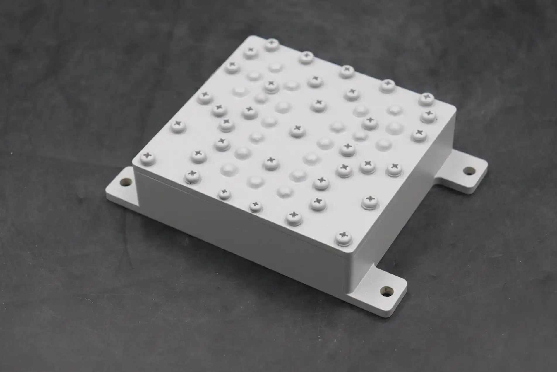
Analyzing the Cavity Q Factor Limits on Insertion Loss
The highest Q numbers that can be reached are limited by the qualities of the materials used. Copper wires that have been coated with silver can have surface resistivities below 2×10⁻⁸ Ω·m at room temperature. This means that in well-designed X-band cavities, Q factors can be higher than 8000. Because they are cheaper and lighter, aluminium housings tend to stop working around Q = 4000 because they have a higher natural resistance. When you machine something, the surface gets rough, which leads to more losses because the depth of the skin matches the smoothness of the surface at higher frequencies. This is a problem above 20 GHz.
Material Conductivity and Surface Finish Effects
At 2.4 GHz, the skin depth of copper is about 1.3 micrometers, which means that most of the current is in a tiny layer on the surface. Any oxidation, pollution, or roughness in this vital zone makes the resistance much higher. When surface finishes go over Ra = 0.8 micrometers, Q drops by 15–20% compared to electropolished surfaces that get Ra < 0.2 micrometers. Silver plating protects copper from oxidation and makes the conductivity 5% higher than raw copper. Gold plating, on the other hand, is better for coastal or warm settings because it resists corrosion better, even though it has slightly lower conductivity.
Frequency-Dependent Trade-Offs
The relationship between bandwidth and insertion loss forces engineers to make trade-offs. To improve selectivity by narrowing the frequency, better resonator coupling is needed. This loads the cavity and lowers effective Q, which raises insertion loss. If you center a 3% bandwidth filter at 10 GHz, you might get 0.8 dB of insertion loss with Q = 4500. But if you narrow the bandwidth to 1%, you might get more than 1.5 dB of loss, even if the cavity construction stays the same. To avoid expensive performance gaps, procurement teams must tell suppliers exactly what selectivity standards they need to meet early on in the design phase.
Simulation Methodologies and Validation
Modern electromagnetic modelling tools that use finite element methods (FEM) or the method of moments (MoM) can accurately predict the Q factor before the device is made. To predict insertion loss within ±0.15 dB across temperature ranges, these tools take into account the effects of wire skin, dielectric properties, and geometric tolerances. However, the accuracy of the simulation relies heavily on the material properties that are used. For example, conductivity values recorded at DC are very different from microwave frequencies because of surface roughness and plating errors. Validated designs are tested with a network analyser in controlled 50-ohm settings. If there are any differences between modelling and measurement, they are sent for material analysis or dimensional verification.
Real-World Performance Case Studies
For a recent space project of Coaxial Bandpass Filter, L-band filters with insertion loss below 0.6 dB and a 140 MHz frequency centred at 1575 MHz were needed. When standard aluminium housings were used for the first prototypes, they gave Q = 3200 and 0.95 dB loss. By switching to a copper structure with silver plating, Q went up to 5800, loss went down to 0.52 dB, and the mechanical strength for settings with vibration stayed the same. The new materials cost an extra $180 per unit, but they got rid of the need for adjusting amplification, which saved $400 on downstream parts and 2.5 watts of prime power.
Comparison of Coaxial Bandpass Filters with Alternative Filter Types
To choose the best filter design, you have to balance electrical performance with price and space limitations. Coaxial resonator designs are special because they are in a unique spot between small planar technologies and high-performance waveguide solutions. This makes them perfect for business-to-business uses that need to handle modest power and have good Q factors.
Technology Performance Matrix
When it comes to narrow-bandwidth uses, cavity filters with rectangular or circular waveguide resonators have the highest Q factors, often surpassing 15,000 at the C-band, which means that insertion losses are below 0.3 dB. Because they are so big and heavy, they can only be used in stable systems like broadcast combiners or ground-based radar. When microstrip filters are made on dielectric surfaces, they are the smallest and easiest to integrate. However, they have Q limits around 200–400, which means that they have insertion losses above 2 dB unless the frequency is millimetre waves, in which case the spread dimensions become helpful.
Ceramic dielectric resonator filters offer options in the middle, with Q values ranging from 800 to 3000, based on the quality of the dielectric material. They aren't very useful in aircraft because they have trouble staying stable at high temperatures and breaking easily when they're loaded suddenly, but they are the standard in business cell phone base stations, where the environment can be controlled. Surface acoustic wave (SAW) devices work great in pocket systems that need very small solutions below 3 GHz. However, they can't be used in infrastructure because they have insertion losses of 3–6 dB and can only handle a small amount of power (usually less than 1 watt).
Application-Specific Selection Criteria
When choosing filters for satellite ground station feeds that work at about 12 GHz with 500 watts of constant power, coaxial combline designs offer Q factors of around 6000 and are built to last. The usual insertion loss of 0.7 dB protects the purity of the signal while handling thermal loads that would damage ceramic options. When defence companies make airborne electronic warfare pods, they focus on making them tough and able to work in temperatures ranging from -55°C to +85°C. They also like coaxial designs with hermetically sealed connections, even though they are more expensive than commercial microstrip choices. Coaxial Bandpass Filters from well-known sources are often chosen by telecom system designers who use 2.4 GHz ISM band equipment. Pasternack has models with an 80 MHz frequency and 1.2 dB insertion loss that work well for point-to-point links. Mini-Circuits, on the other hand, has surface-mount hybrid designs that are easy to use and have 1.8 dB loss for integrating equipment. Murata's ceramic resonator filters are made for low-cost market uses where 2.5 dB loss is still fine because the filters are small (less than 10 cm³).
Design Principles to Minimize Insertion Loss in Coaxial Bandpass Filters
To meet the requirements for insertion loss below 1 dB, the design, manufacturing, and testing cycles must be carefully followed. The choice of material is the first step, but geometric optimisation and industrial accuracy are what really show if the performance predicted in theory works in practice in Coaxial Bandpass Filters.
Material Selection Strategies
High-conductivity oxygen-free copper is the best material for resonator rods and housings because it has a conductivity of about 5.8×10⁷ S/m when it is properly tempered. The best silver plate thickness is between 3 and 7 micrometers; thinner coatings can leave pinholes that let oxidation happen to the copper underneath, and too much thickness loses material without better performance beyond skin deep penetration. Low-loss dielectric supports, like PTFE or Rexolite, for any standoffs that may be needed, keep loss tangents below 0.0005 at microwave frequencies, which means they don't contribute much to dissipation compared to conductor effects.
Geometric and Dimensional Optimization
The ratios of the resonator's width to length have a big effect on the Q factor through mode purity and field concentration. Combline topologies use shorter quarter-wave resonators with capacitive loading to get 30–40% smaller structures than half-wave structures while keeping Q values within 15% of designs that are not loaded. Coupling iris sizes need to be accurate to within 0.05 mm. Too many coupling holes increase bandwidth, but lower insertion loss by adding more resistive loading, and not enough coupling causes passband noise and return loss degradation.
Manufacturing Precision and Quality Control
Tolerances of ±0.025 mm in CNC cutting make sure that the resonator frequencies stay in the tuning range. This is because a 0.1 mm length mistake moves the resonance by about 25 MHz at 10 GHz. Using electroforming to make housings that are smooth gets rid of the leakage lines that lower the Q factor and make the shield less effective. Tuning screws made of brass that have been plated with silver allow for frequency adjustment after assembly, usually within ±2% of the center frequency. This accounts for changes in the material's properties and the effects of thermal expansion across a range of working temperatures.
When you work with a reliable supplier, you can use design libraries and production methods that have been tried and tested for decades. Vendors that keep their ISO 9001 certification and use statistical process control can guarantee stability from batch to batch, which is important for large-scale deployments. We've seen over and over that sellers who are willing to share Q-factor measurement data and insertion loss temperature coefficients show a strong commitment to openness that is strongly linked to long-term product reliability.
Procurement Guidance and Supplier Insights for Coaxial Bandpass Filters
To successfully navigate the procurement market, you need to look at both technical requirements and the supplier's skills and terms of business for any Coaxial Bandpass Filter. Datasheets that aren't full or performance promises that aren't clear can be signs of quality problems that show up in the field as failures or expensive redesign processes.
Technical Specification Evaluation
Full datasheets show insertion loss across the whole passband, not just at one frequency. This shows wave features that affect the quality of the signal. Temperature coefficients that show changes in loss from -40°C to +85°C show thermal stability. Filters that show a loss rise of more than 0.3 dB over this range may need active adjustment or environmental control. Transparency in the Q factor, which is sadly lacking among some commercial vendors, lets you directly compare performance. Suppliers that post unloaded Q values show technical trust and engineering rigour.
Return loss specifications below 15 dB across the passband show poor impedance matching that creates echoes, which could make the amplifier unstable or lead to measurement mistakes. Reliable makers promise a low return loss of 20 dB, and high-end designs can reach 25 dB through better coupling networks. Power handling ratings must include peak and average limits along with duty cycles. For example, a filter rated "50 watts" without any further information could fail at 30 watts of constant operation because of solder joints or dielectric supports overheating.
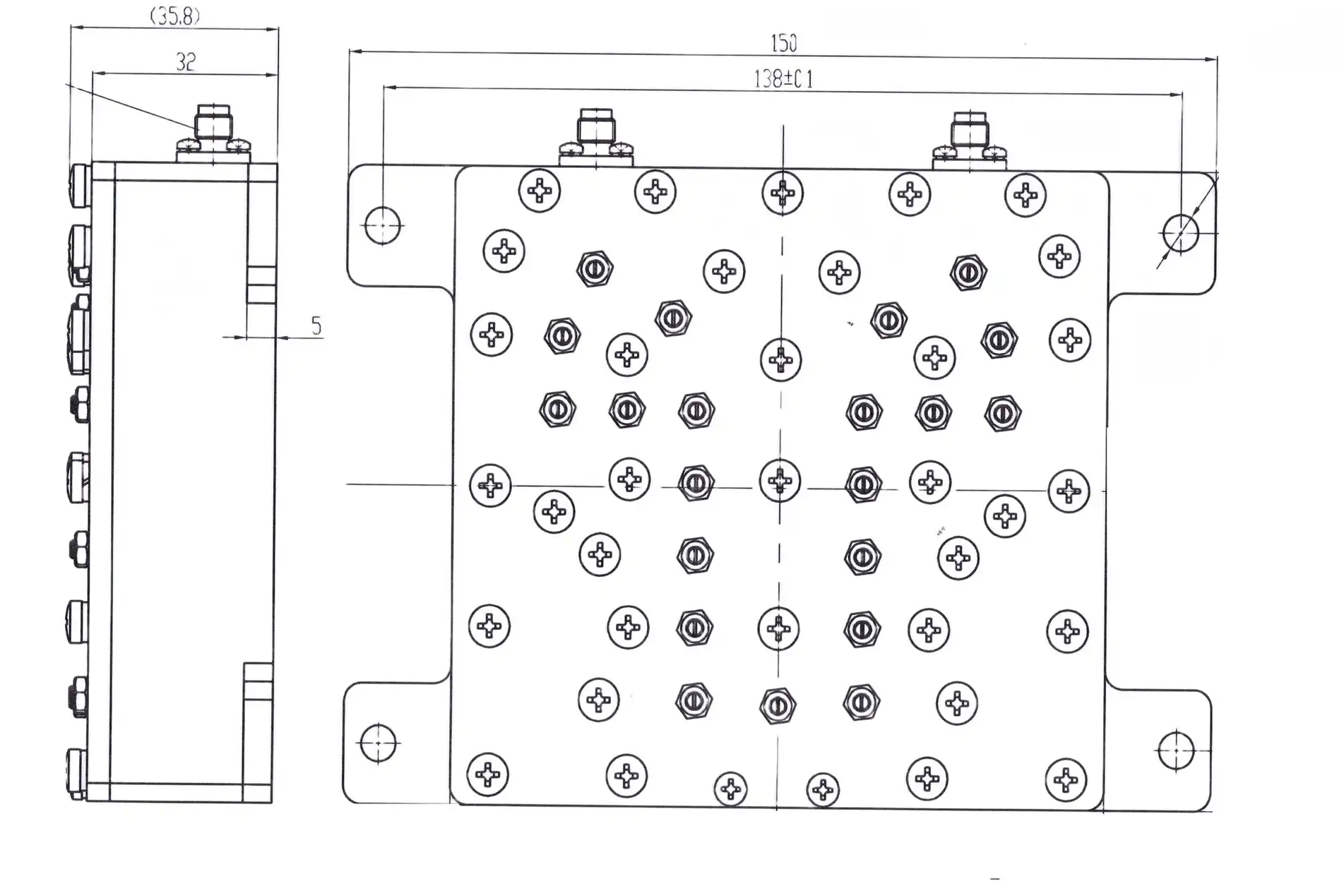
Custom Versus Catalog Solutions
Off-the-shelf filters from Pasternack, Mini-Circuits, and other related suppliers work well for uses with standard frequency plans and average performance needs. Catalogue items are good for testing and small production runs because they come with lead times of 2 to 6 weeks and prices that start at $150 to $400 per unit for large orders. When requirements call for unusual bandwidths, strict temperature stability, or interaction with certain connector types and mounting setups, custom designs become cost-effective when ordered in numbers above 100 units.
Custom filter development usually takes 8–14 weeks, from finalising the specifications to delivering the prototype. An extra 3–4 weeks are needed to set up production. Tooling costs of $3,000 to $8,000 are spread out over the number of pieces that are made. When more than 500 pieces are made, unit costs often drop by 30 to 45 percent compared to catalogue copies. During the customisation process, there needs to be a lot of technical communication about things like environmental exposure, shock/vibration profiles, and interface requirements. During this phase, suppliers who provide dedicated application engineers come up with solutions that work in real-world situations, not just in a lab.
Logistics and Support Considerations
When precision RF parts are shipped internationally, they need to be packed in the right way to protect them from damage caused by mechanical shock and to keep moisture out of the environment. Suppliers who offer personalised foam inserts and humidity warning cards show that they know how field failures happen. The warranty should cover both major failures and performance drift. A two-year guarantee that covers return loss and insertion loss proof is a good way to protect yourself.
After-sales technical support distinguishes professional manufacturers from component brokers. Long-term worth goes beyond the initial purchase price when you have access to application experts who can help with network integration, impedance matching problems, or suggest different models as needs change. We make it a priority for sellers to keep measurement tools that can be linked to national standards labs. This way, if there are any disagreements about acceptance testing results, a third party can check them.
Conclusion
The complex relationship between cavity Q factor and insertion loss shapes how well a Coaxial Bandpass Filter works in high-power RF systems. Material conductivity, surface finish quality, and geometric accuracy all play a role in figuring out if filters meet the strict requirements for satellite ground stations, aircraft radar, or telecommunications infrastructure. When making purchases, it's helpful to know how these technical factors affect each other because it lets you weigh the pros and cons of size, cost, and electricity performance. When getting mission-critical parts, there are risks that come with them. To lower those risks, suppliers must be carefully evaluated, with a focus on clear datasheets, factory quality certifications, and quick expert support. As frequency needs move toward millimeter-wave bands and link costs get tighter, it becomes more important to work with experienced makers to get reliable, high-performance filtering options.
FAQ
1. What insertion loss should I expect from a well-designed coaxial bandpass filter?
How much insertion loss there is depends on the frequency, bandwidth, and cavity Q factor. At 2.4 GHz and 100 MHz bandwidth, Coaxial Bandpass Filters that are properly built usually lose between 0.8 and 1.2 dB. Because of the tighter coupling needs, narrower bandwidths may raise the loss to 1.5–2.0 dB. On the other hand, wider bandwidths that are close to 10% of the center frequency can lower loss below 0.7 dB. When the frequency goes above 10 GHz, skin effect and smaller limits for dimensions usually cause more loss.
2. How does cavity Q factor differ from loaded Q?
Unloaded Q is the resonator's natural ability to store energy without any outside connection, and it is only determined by the losses in the conductors and dielectrics. Loaded Q always measures less than empty Q because it takes into account the effects of input/output coupling and external circuit loads. The connection between these factors and insertion loss depends on the coupling coefficient and the bandwidth needs. For accurate comparisons, purchase specs should use unloaded Q.
3. Can I improve filter performance through better connector selection?
Overall insertion loss is affected by the quality of the connector in a big way, especially above 6 GHz, where contact resistance and impedance gaps become clear. It is estimated that premium SMA connectors with gold-plated beryllium copper contacts lose about 0.05 dB per pair, while cheaper models may lose up to 0.15 dB. When links are properly torqued (8–10 inch-pounds for SMA), passive intermodulation is kept to a minimum, and readings can be repeated during acceptance testing.
Partner with ADM for Superior RF Filtering Solutions
Advanced Microwave Technologies Co., Ltd has been designing and making high-performance Coaxial Bandpass Filters for the military, defence, and satellite communication industries for more than twenty years. Our manufacturing methods are ISO 9001:2015 approved, so the quality is the same from one run to the next. Our 24-meter anechoic chamber lets us test everything up to 110 GHz. We know that procurement experts need more than just datasheets. They need a manufacturer that is committed to openness, customisation, and quick technical support. Our engineering team works directly with your design team to make sure that the filter specs are perfect for your frequency plans, power handling needs, and the surroundings. You can get precision RF parts from ADM, along with full test paperwork and global logistics support, whether you need fast prototyping for proof-of-concept systems or high-volume production with strict tolerance control. Get in touch with craig@admicrowave.com to talk about your filtering needs and find out how our technical skills and focus on customer satisfaction can improve the stability of your supply chain.
References
1. Matthaei, George L., Leo Young, and E.M.T. Jones. Microwave Filters, Impedance-Matching Networks, and Coupling Structures. Artech House Publishers, 1980.
2. Hong, Jia-Sheng, and M.J. Lancaster. Microstrip Filters for RF/Microwave Applications. John Wiley & Sons, 2001.
3. Pozar, David M. Microwave Engineering, 4th Edition. Wiley, 2011, Chapter 8: Microwave Filters.
4. Cameron, Richard J., Chandra M. Kudsia, and Raafat R. Mansour. Microwave Filters for Communication Systems: Fundamentals, Design, and Applications. Wiley-Interscience, 2007.
5. Collin, Robert E. Foundations for Microwave Engineering, 2nd Edition. IEEE Press, 2001, Chapter 7: Cavity Resonators and Filters.
6. Levy, Ralph, et al. "Design of General Chebyshev Coaxial Cavity Filters." IEEE Transactions on Microwave Theory and Techniques, Volume 50, Issue 12, December 2002, pages 2950-2956.