Broadwall Double Ridge Waveguide Coupler: Multi-Hole Design
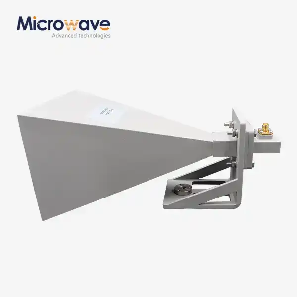
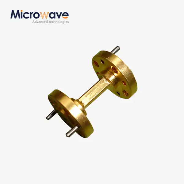
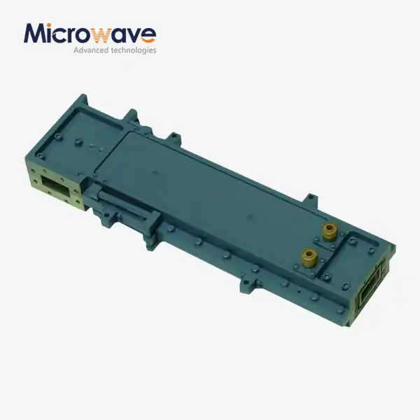
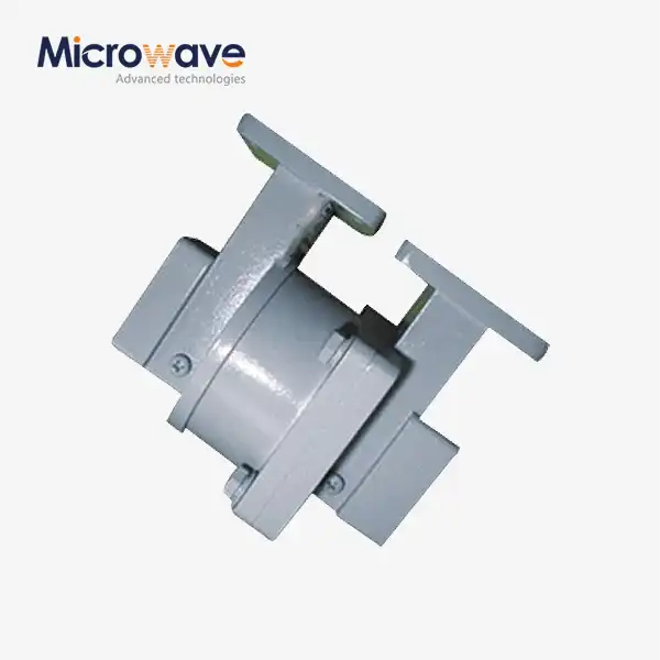
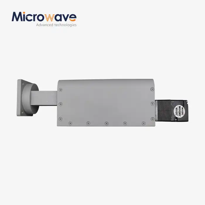
A broadwall double-ridge waveguide coupler is a high-tech passive microwave part designed to sample or combine RF signals while providing excellent directional isolation over very large frequency ranges. In contrast to regular rectangular waveguides, which can only work in small frequency ranges, the double ridge geometry loads the waveguide center capacitively, which lowers the cutoff frequency by a large amount and raises the higher-order mode limits. This new technology makes it possible to have bandwidths that cover multiple octaves, such as 2–18 GHz or 6–40 GHz. This solves the important size-versus-bandwidth problem in electronic warfare and wideband measurement systems. There is a lot of information in this guide about these couplers, especially about how the multi-hole design improves speed and bandwidth. It's our job to meet the needs of procurement engineers, technical sourcing teams, original equipment manufacturers, and system integrators who work in research, defense, aerospace, and satellite communications. Understanding the technology design and buying issues helps people make decisions about how to best integrate systems and build trustworthy supply chain partnerships that meet mission-critical needs.
Understanding Broadwall Double Ridge Waveguide Couplers
Fundamental Working Principles
The broadwall double-ridge waveguide coupler works by connecting electromagnetic waves efficiently through carefully designed holes in the broadwall surface. The double-ridge structure has two metal ridges that run parallel to each other inside the waveguide. This makes a special electromagnetic field distribution. This arrangement drops the basic TE10 cutoff frequency while keeping the next higher-order mode frequency high. This makes the usable single-mode bandwidth bigger, going from about 40% in standard waveguides to over 200–300% in double-ridge designs.
The multi-hole design is very important for getting even connections over a wide frequency range. Putting coupling holes in the right places, usually in a Tchebyscheff design, lets controlled electromagnetic energy move from the main waveguide channel to the coupled port. The size, spacing, and location of each hole are calculated to make sure that the coupling values are always the same with the least amount of frequency sensitivity. Usually, changes in these values stay within ±1.0 dB across the whole operational band.
Manufacturing Materials and Performance Impact
At ADM, we make these couplers with high-quality copper alloys and aluminum 6061-T6 that are chosen for their good electrical conductivity and mechanical stability. Special finishes, like chromate conversion coatings or silver plating, are put on the inside to reduce resistive losses and stop corrosion in harsh working conditions. The choice of material has a direct effect on insertion loss, the ability to handle power, and the reliability over time. For flying uses where weight is very important, aluminum is a good choice. Copper, on the other hand, is better for laboratory-grade measurement systems that need to keep signal degradation to a minimum. The most important manufacturing dimension is the ridge gap tolerance. Differences of only a few microns can change the cutoff frequencies and hurt performance.
Design Principles and Performance Characteristics
Key Design Elements
The performance excellence of Broadwall double-ridge waveguide couplers stems from careful electromagnetic and structure engineering. The width and shape of the broad wall and the geometry of the ridges directly affect how well they couple. The impedance characteristics and bandwidth extension are determined by the height and distance between the ridges. The multi-hole coupling array sets up controlled phase relationships between signals that are linked, which makes it very direct by using precise wave suppression mechanisms.
We handle a number of broadwall double-ridge waveguide coupler WRD standards, such as WRD650, WRD750, and WRD180, which cover frequency ratios higher than 3.6:1. The coupling flatness across these wide bands comes from carefully optimizing the hole distribution patterns, which strikes a balance between making the coupling regular and making the device easy to make. Our designs keep VSWR below 1.4:1 across all operational frequencies. This makes sure that the impedance matching is perfect, which reduces signal reflections and keeps the system's integrity.
Performance Metrics and Bandwidth Capabilities
Directivity is usually higher than 20 dB across most of the operating band. This makes sure that reflected signals don't cause too much interference during forward power tracking tasks. This performance comes from the coupling apertures being carefully machined so that phase relationships stay the same even when the frequency changes a lot. As the electrical distance between holes changes from the ideal quarter-wavelength spacing, directivity may drop a little to 15 dB at the band ends. However, this is still enough for demanding uses.
Power handling skills are much better than coaxial options, with ratings that can hit kilowatt levels based on frequency and pressurization. Because of this benefit, double ridge couplers are necessary in EMC compliance labs and high-power radar testing labs where high power must be used continuously without temperature drift. Insertion loss stays very low thanks to careful attention to finishing the inside surface and making sure there is good contact at the flange interfaces.
Comparing Broadwall Double Ridge Waveguide Couplers with Alternatives
Structural and Performance Distinctions
When looking at waveguide couplers, knowing about the different design options helps you make the best buying decisions. Single ridge couplers are a little better at increasing bandwidth than regular rectangular waveguides, but they can't match the performance of double ridge setups when it comes to multiple octaves. In double-ridge designs, the placement of the ridges is symmetrical, which improves impedance control and makes the field distribution more uniform. This leads to better coupling flatness and lower insertion loss over wider bandwidths.
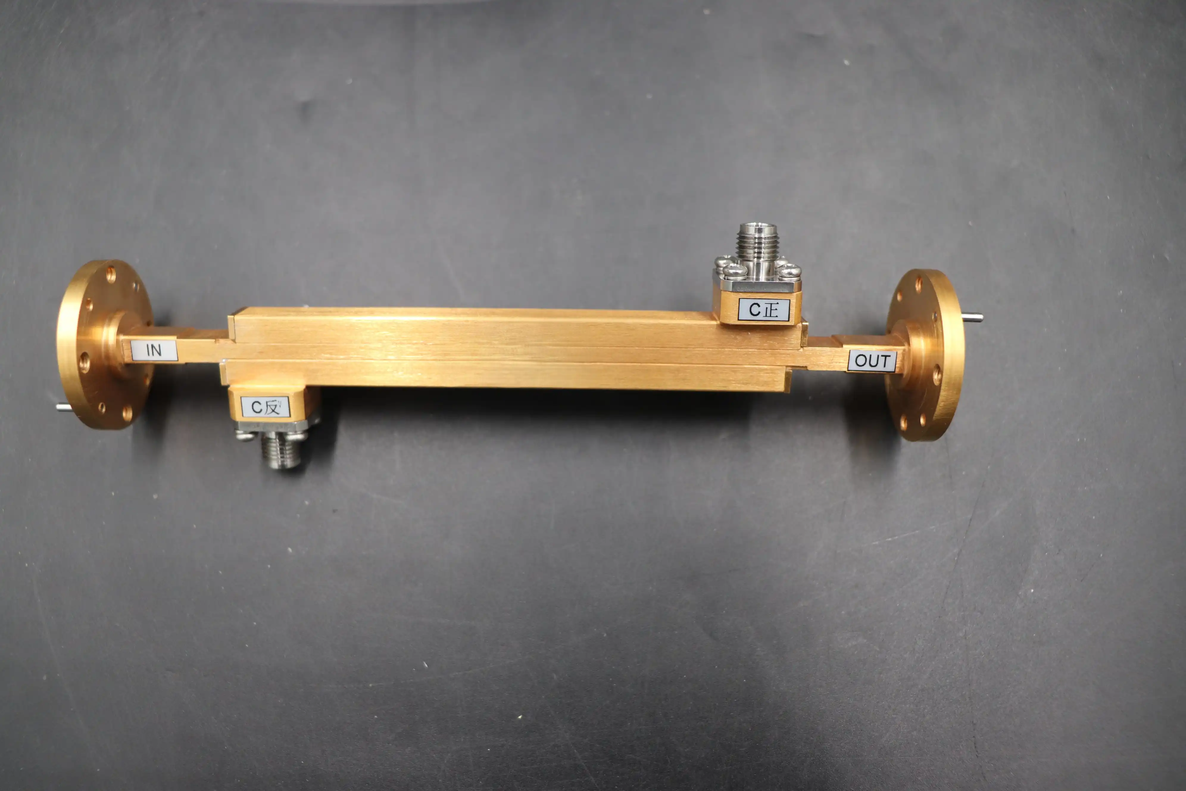
Narrowwall double ridge couplers put the ridges along the narrow wall instead of the wide wall. This configuration works well in some situations where room is limited, but broadwall designs handle power better and have lower insertion loss. The bigger coupling surface area lets you use more complex multi-hole patterns, which gives you more precise control over the frequency response and directivity profiles.
Procurement Considerations and Cost-Performance Balance
The money spent on broadwall double-ridge waveguide couplers pays off in a big way at the system level. Getting rid of the need for multiple standard waveguide couplers to cover a wide range of frequencies makes the system lighter, simpler to build, and less likely to lose signal over time. This consolidation is especially helpful in aircraft electronic warfare kits that have to meet strict size requirements and multi-octave frequency coverage needs. The higher cost of the original parts is balanced by a simpler system design, less maintenance, and more operating flexibility. Instead of just looking at unit price, procurement teams should also look at the total cost of ownership, which includes things like how hard it is to integrate, how reliable the provider is in the long term, and how well they can help with technology issues.
Practical Applications and Installation Guidelines
Industry Applications
Broadwall double-ridge waveguide couplers are very important in many high-performance areas. These parts keep an eye on the power going to antenna arrays in airborne electronic warfare systems without the need for multiple hardware chains. They can handle the high vibrations and fast temperature changes that come with flying. Defense contractors use them in systems that jam signals and find threats because their small size and ability to cover multiple octaves are very important.
Another important area of use is high-power broadband radar tests. These couplers allow automated test equipment for synthetic aperture radar to constantly sweep full operating bands. This lets the equipment test traveling wave tubes and solid-state power amplifiers without breaking vacuum or waveguide connections. They are used by EMC compliance labs to feed high-power broadband antennas. They do this by creating exact feedback loops that keep field strengths constant across octaves during radiated immunity tests.
Universities and research institutions use broadwall double-ridge waveguide couplers in testing sets that need to be able to cover a wide range of frequencies and make accurate measurements. Characterizing wideband devices with a single connection speeds up the development process and lowers the cost of tools for labs that are trying to stick to a budget.
Installation and Maintenance Best Practices
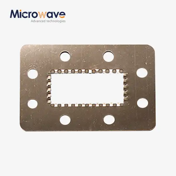
Making sure the flanges are compatible is the first step in a proper fitting. These couplers use certain WRD flanges, like the FP or FDP series. When matching interfaces, you need to pay attention to whether they need flat covers or grooved gasket faces to make sure the right VSWR match and airtight closing are achieved. At high power levels, where even small surface flaws can hurt performance, flange planarity checking stops RF leakage and arcing.
During integration, keep the mating surfaces clean and free of any dirt or rust. To make sure the pressure is spread evenly, torque the flange screws according to the manufacturer's instructions in a star design. For applications that use pressurized air, test for leaks with dry air or nitrogen to make sure the seal is still intact before putting it to use.
Regular upkeep checks the VSWR and insertion loss using measured vector network analyzers on a regular basis. Check the stability of the coupling factor over time, as changes could mean that the inside is breaking down or getting contaminated. When using a lot of power, check the connection holes and flange surfaces for signs of arcing or thermal stress. Keeping detailed records of calibration makes it possible to find performance drift early on, which supports predictive maintenance strategies that increase uptime.
Procurement Guide for Broadwall Double Ridge Waveguide Couplers
Sourcing from Reliable Manufacturers
To do successful buying, you need to work with providers who can offer strong quality assurance and full support, not just pick specs. ADM has been making precise microwave parts for more than 20 years, and our ISO 9001:2015 certification shows that we are dedicated to quality management systems. Our 24-meter microwave darkroom lets us test antenna and waveguide performance thoroughly over the 0.5–110 GHz frequency range, making sure that every part meets or goes beyond the published specs.
When looking at different providers, make sure they can give you full S-parameter paperwork that has been checked by a vector network analyzer. Reputable manufacturers test their products 100% for radio frequency (RF) and, if necessary, compare the results to MIL-DTL-85 standards. Ask for proof that the dimensions were checked using coordinate measuring machines, especially for important factors like ridge gap tolerance that depend on accuracy down to the micron level.
Customization and Order Fulfillment
Our OEM services can meet a wide range of needs, from fast prototyping for R&D testing to large-scale production for system installers. Customization choices include custom coupling values, unique flange designs, weather protection for harsh conditions, and special coatings for use at high altitudes or in vacuums. We work closely with procurement teams to understand the limits of the system and then suggest the best solutions that balance technical performance with delivery and cost needs.
Our integrated production infrastructure lets us handle large orders and offer reasonable pricing for long-term commitments. We also keep the freedom to deliver in stages that work with your manufacturing plans. Standard configurations usually have lead times between four and eight weeks, but there are faster options for those who need them right away. We keep clear lines of communication open throughout the entire manufacturing process, giving regular updates and advance notice of any changes that might affect the plan.
We're confident in the reliability of the broadwall double-ridge waveguide coupler parts we sell, so the warranty terms cover everything from manufacturing flaws to performance differences. Throughout the lifecycle of a product, our technical support team is available to help with installation, troubleshooting, and making suggestions for improving performance. This partnership-based method helps procurement workers lower risks and get the best results from system integration.
Conclusion
Broadwall double ridge waveguide couplers with multi-hole designs are a high-tech way to solve problems that need a lot of power, a wide bandwidth, and high directivity. When you combine double ridge geometry with carefully designed coupling apertures, you get multi-octave performance that makes system architectures easier to understand and improves reliability. These parts are the technical basis for mission-critical RF applications, like those used in electronic warfare, radar development programs, or precise measurement systems. Partnering with experienced makers who can combine advanced manufacturing with thorough quality assurance and quick technical support is key to successful procurement. This makes sure that parts meet strict specs and arrive on time.
FAQ
1. How does the double-ridged geometry improve bandwidth compared to standard waveguide couplers?
Because the ridges add capacitance to the waveguide, the basic TE10 cutoff frequency goes down while the next higher-order mode frequency stays high. This makes the usable single-mode bandwidth bigger, from the usual 40% in standard waveguides to over 200–300% in double-ridge arrangements, which lets them cover more than one octave.
2. What coupling accuracy can be expected across the full frequency band?
Most of the time, multi-hole broadwall designs keep the mean coupling accuracy within ±1.0 to ±1.5 dB across the whole operational range. Tighter standards are reached by carefully CNC milling the connection holes and improving the way the holes are spread out.
3. Can these couplers handle high peak power in demanding environments?
Of course. When compared to coaxial lines, these devices can handle more power, which is usually measured in kilowatts. When the product is not under pressure, it's important to pay attention to the altitude derating. In vacuum or high-altitude situations, special coatings stop multipaction.
4. Why does directivity decrease at band edges?
At coupling holes, phase cancellation is what makes directivity possible. At the edges of multi-octave bands, the electrical distance between holes is not exactly a quarter-wavelength apart, which makes separation a little less good. Even at the edges of the band, good designs keep directivity above 15 dB.
Partner with ADM for Superior Broadwall Double Ridge Waveguide Coupler Solutions
ADM is ready to help you with your purchasing needs by providing broadwall double ridge waveguide couplers that are designed to work exceptionally well across multiple octaves. Our manufacturing know-how, which is backed up by ISO 9001:2015 approval and modern measurement tools that can reach up to 110 GHz, guarantees that the parts we make will meet your strictest requirements. As a well-known manufacturer and supplier, we can offer you custom designs, low prices for large orders, and fast prototyping services that cut down on the time it takes to develop new products. Our expert team helps with every step of the buying process, from helping with the initial specifications to guiding you through installation and suggesting long-term care. Get in touch with craig@admicrowave.com right away to talk about your needs and find out how our broadwall double ridge waveguide coupler solutions can improve the performance of your RF system and make sure the supply chain is reliable.
References
1. Bhat, B., and Koul, S. K. (1987). Stripline-Like Transmission Lines for Microwave Integrated Circuits. New York: Wiley.
2. Marcuvitz, N. (1951). Waveguide Handbook, MIT Radiation Laboratory Series, Volume 10. New York: McGraw-Hill.
3. Chen, Y. (2005). "Design and Analysis of Double-Ridged Waveguide Directional Couplers." IEEE Transactions on Microwave Theory and Techniques, 53(6), 2123-2130.
4. Saad, T. S. (1971). Handbook of Microwave Integrated Circuits. Norwood: Artech House.
5. Hopfer, S. (1955). "The Design of Ridged Waveguides." IRE Transactions on Microwave Theory and Techniques, 3(5), 20-29.
6. Montgomery, C. G., Dicke, R. H., and Purcell, E. M. (1948). Principles of Microwave Circuits, MIT Radiation Laboratory Series, Volume 8. New York: McGraw-Hill.