





What Is a Waveguide Fixed Attenuator and When Do You Need One?
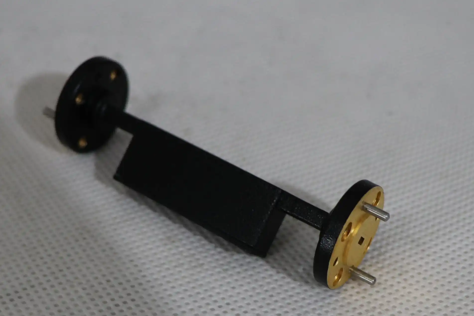
A waveguide fixed attenuator is a passive microwave component that reduces signal power by a precise, predetermined amount — measured in decibels (dB) — without distorting the waveform or significantly shifting its phase. Integrated directly into a waveguide transmission line, it works by placing a resistive vane or lossy dielectric material inside the waveguide cavity to absorb RF energy and convert it to heat. Engineers across defense, satellite communications, and RF test labs rely on this component to protect sensitive receivers, improve VSWR, and extend the dynamic range of measurement instruments.
Understanding Waveguide Fixed Attenuators
Definition and Core Operating Principle
A waveguide fixed attenuator always gives the same dB value across its rated frequency band, while a variable attenuator lets you change the reduction value. The resistance element, which is usually a silicon carbide vane or a ferrite ceramic wedge, is put inside the guide so that it is parallel to the electric field. Because of its shape, the part can evenly receive RF power and turn it into heat energy. The end result is a precise, stable signal reduction that sends very little back to the source.
Key Electrical and Physical Specifications
Understanding the specifications keeps you from making mistakes that cost a lot of money. Some important factors are the quality of the reduction (usually ±0.3 dB to ±1.0 dB), the VSWR (usually ≤ 1.20:1), and the average CW power handling. For X-Band (8.2–12.4 GHz), the EIA waveguide size is WR-90; for Ka-Band (26.5–40 GHz), it's WR-28; and for W-Band (75–110 GHz), it's WR-10. Oxygen-Free Copper (OFC), Aluminum 6061, or brass are used to make the housings. They are then plated with silver or gold to lower skin-effect losses.
Types Based on Frequency, Power, and Configuration
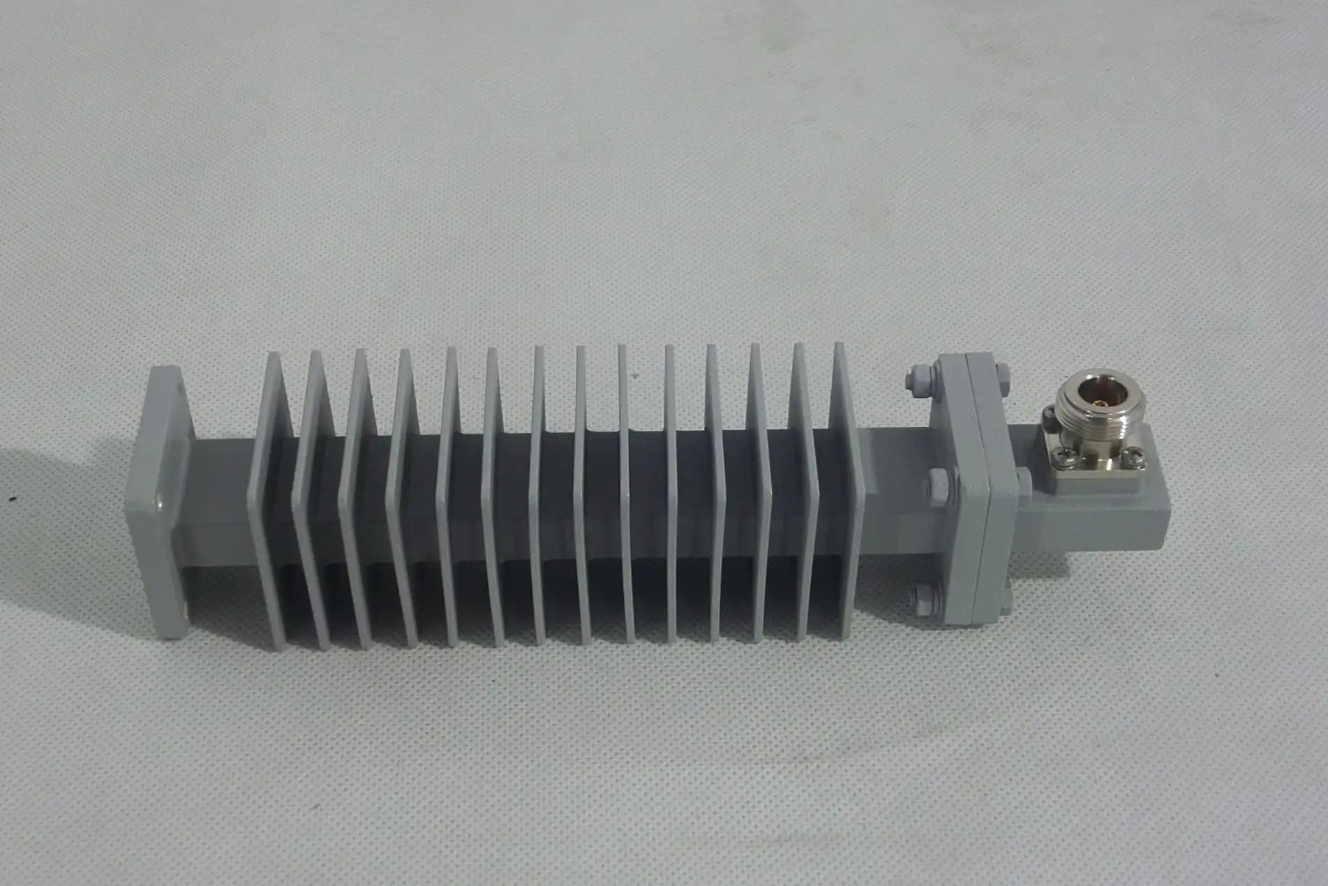
Waveguide fixed attenuators are different depending on the frequency band, power class (low-power laboratory vs. high-power kilowatt-rated), flange type (UG-style, choke, or cover flange), and absorption material. High-precision "metrology grade" units have a VSWR of less than 1.10:1 and an attenuation flatness of ±0.2 dB across the band. This means they can be used to calibrate VNAs. In production settings, standard-grade units can handle VSWR up to 1.25:1 and are good for basic signal conditioning jobs.
Applications and Benefits of Waveguide Fixed Attenuators
These attenuators are used in defense, satellite, and test environments to solve a common set of engineering issues. They keep receivers from becoming saturated, separate source impedance mismatches, and level signal paths in multi-channel systems. Here are three real-life examples of how they can be used to make a big difference:
- SATCOM Earth Station Uplinks: In high-power amplifier (HPA) chains, a waveguide fixed attenuator that stays in place lowers transmission signals from kilowatts to milliwatts, which is safe for spectrum analyzers to use during loop-back testing. This keeps the stability of the tracking system without stopping the main uplink beam, which is what professional Earth stations always do.
- Defense Radar Transmit/Receive Modules: Fixed attenuators act as isolation pads between the oscillator and antenna array in T/R modules. They lower standing waves that are caused by antenna impedance mismatches, protecting magnetron or solid-state sources from destructive reflected power in complex electromagnetic environments.
- Millimeter-Wave R&D Test Labs: For 5G and 6G component characterization, attenuators drop the output of an amplifier into the linear range of a power sensor. This lets you measure linearity and gain compression accurately without overloading the instrument, which is necessary when testing devices that work above 26 GHz.
These three examples show why matching the frequency and power is just as important as the reduction number itself. A device made for X-Band won't be able to send messages in Ka-Band, and an amplifier that's supposed to handle 10 W of average power won't work with a 100 W CW signal.
Comparing Waveguide Fixed Attenuators with Alternatives
Fixed vs. Variable Attenuators
Variable attenuators let you change the amount of reduction, which works well for uses that need to control power in real time, like AGC loops or antenna test range leveling. A waveguide fixed attenuator, on the other hand, offers more stable insertion loss, lower VSWR, and higher power handling in a package that is easier to repeat. Because the attenuation value can't change, fixed types are the best choice for standardized test sets and signal conditioning on the production line.
Waveguide vs. Coaxial Attenuators
Coaxial attenuators are cheap and come in small packages that can handle a wide range of frequencies. But above about 18 GHz, cable connection losses rise sharply, and they can't handle as much power. Waveguide designs can handle much higher average and peak power and lower insertion loss variation over a wide range of millimeter-wave bands. The waveguide architecture is better in terms of technology for radar, SATCOM uplinks, and high-power test systems above Ku-Band.
Notable Suppliers in the Market
There are a number of well-known suppliers in this space. With short wait times, Pasternack has a large selection of standard waveguide attenuators. Maury Microwave is known for making accurate parts that are good enough for measurement. Keysight Technologies sells attenuators that are built into their test and measurement ecosystem. TE Connectivity meets the production needs of OEMs. Each seller is trying to get business from a certain group of people, so it's a good idea to match the profile of the provider to the needs of the application.
How to Select the Right Waveguide Fixed Attenuator
Define System Parameters First
Write down the operating frequency band, the required attenuation value (dB), the maximum average CW power, and the peak power before you call any suppliers. Then, set appropriate limits for VSWR and insertion loss flatness. Right away, these four factors cut down the waveguide size and grade. For instance, a 10 dB waveguide fixed attenuator for a 30 GHz ground station that is running 50 W CW needs to be WR-28 sized and have a heat absorption design that has been tested to handle that much power all the time.
Evaluate Environmental and Mechanical Constraints
Stable temperatures are important for operations in the air or outside. High-quality attenuators use absorber materials that don't change much when the temperature does, and they keep the change in attenuation to less than 0.005 dB/°C. Make sure that the type of flange fits with the waveguide part that goes with it in your setup. When flanges don't match, air gaps appear between them. These gaps lower VSWR and cause leak points in waveguide runs that are pressurized or completely sealed.
Procurement and Supplier Qualification Factors
Lead times, minimum order quantities, documentation for tracking, and compliance certifications (ISO 9001, MIL-DTL-3933, RoHS) all have a direct effect on program schedules. Before you approve a supplier, ask for detailed datasheets and S-parameter files. When looking for providers, make sure they offer OEM customization, such as frequency-specific sizing, non-standard attenuation values, or unique flange patterns, because off-the-shelf parts don't always meet all of your integration needs.
Real-World Case Studies and Practical Tips
Case Study: Improving Test Accuracy in a Millimeter-Wave Lab
A university research group that was studying Ka-Band power amplifiers got results from their vector network analyzer (VNA) that were too high above 33 GHz. A measured 20 dB WR-28 waveguide fixed attenuator was put between the output of the device and the VNA port. This brought the signal into the linear measurement range of the instrument. The measurement error went down from ±1.5 dB to ±0.3 dB, which is a direct result of the attenuator's ±0.3 dB accuracy specification.
Common Procurement Pitfalls to Avoid
There are a lot of mistakes that happen when buying waveguide parts from other businesses (B2B). Most people make the mistake of choosing a waveguide size based on the type of connector instead of the frequency range. For example, a WR-90 connector will physically fit a WR-75 system, but it will cause problems with immediate cutoff. A second common mistake is to order standard-grade attenuators for metrology tasks that need flatness within 0.2 dB. Before you approve a purchase order, you should always compare the information to the link budget for your system.
Evaluation Checklist for B2B Buyers
Before placing an order, make sure that the operating frequency band and waveguide size match, that the attenuation accuracy is within the system budget, that the power handling exceeds the maximum expected input, that the VSWR is stated at your frequency, that the flange type is compatible, and that compliance paperwork is provided. Integration risk is cut down a lot when suppliers give you S-parameter (Touchstone) files and traceable calibration data.
Conclusion
A waveguide fixed attenuator is a precise and reliable passive part that fixes real signal integrity issues. It can be used to protect Low Noise Amplifiers in radar systems or to make millimeter-wave readings more accurate in research labs. To choose the right one, you need to make sure that the frequency band, power rating, attenuation accuracy, and flange configuration are all right for your system. Working with a qualified manufacturer that offers full technical documentation and customization help lowers the risk of buying something and boosts the system's performance over time.
FAQ
What frequency ranges do waveguide fixed attenuators typically cover?
The EIA bands that standard waveguide attenuators work with are S-Band (2–4 GHz, WR-284) through W-Band (75–110 GHz, WR-10). The working frequency determines the waveguide size that is needed. If the wrong size is used, the signal will be cut off, or a higher-order mode will propagate.
How do I choose between a fixed and a variable attenuator?
If your system needs stable attenuation that doesn't change while it's running, like with calibration pads or isolation buffers, choose a fixed type. When you need to change the power on the fly, like in automatic gain control (AGC) loops, choose a variable type.
What limits peak power handling?
Peak power is limited not by heat loss but by voltage breakdown (arcing) inside the waveguide. High electric field concentrations at sharp internal shapes can cause the air or pressurized gas inside the waveguide to break down before it gets too hot.
Can a fixed waveguide attenuator be used in both signal directions?
Yes. Most designs are symmetrical and can go in both directions. For very high-power uses, make sure that the heat sink is positioned so that it faces the input port where the resistance element's leading edge takes the most energy.
Does temperature affect attenuation accuracy?
Yes. The material of the absorber changes its resistivity as it heats up under load. Good attenuators are made of materials that don't change much when they get hot or cold. They also keep the change in attenuation to less than 0.005 dB/°C, so the calibration works across all temperature ranges.
Get a Custom Waveguide Fixed Attenuator Quote from ADM
Advanced Microwave Technologies Co., Ltd. (ADM) has been selling high-precision RF and microwave parts for more than 20 years. They are ISO 9001:2015 certified and can measure up to 110 GHz. We are a reliable company that makes waveguide fixed attenuators. For defense, SATCOM, and R&D uses, we offer OEM customization, fast prototyping, and full technical documentation. To get price quotes and datasheets, you can email our engineering team at craig@admicrowave.com.
References
1. Pozar, David M. Microwave Engineering, 4th ed. Wiley, 2011.
2. Collin, Robert E. Foundations for Microwave Engineering, 2nd ed. IEEE Press / Wiley-Interscience, 2001.
3. Montgomery, Carol G., Richard H. Dicke, and Edward M. Purcell. Principles of Microwave Circuits. MIT Radiation Lab Series, Vol. 8. McGraw-Hill, 1948.
4. IEEE Standard 287-2007. IEEE Standard for Precision Coaxial Connectors at RF, Microwave, and Millimeter-Wave Frequencies. IEEE, 2007.
5. MIL-DTL-3933H. Detail Specification: Filters, High Pass, Low Pass, Band Pass, Band Elimination, and Attenuators, Fixed and Variable, RF. U.S. Department of Defense, 2012.
6. Matthaei, George L., Leo Young, and E. M. T. Jones. Microwave Filters, Impedance-Matching Networks, and Coupling Structures. Artech House, 1980.
YOU MAY LIKE
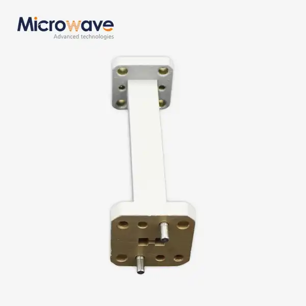 VIEW MOREWaveguide Straights and Transitions
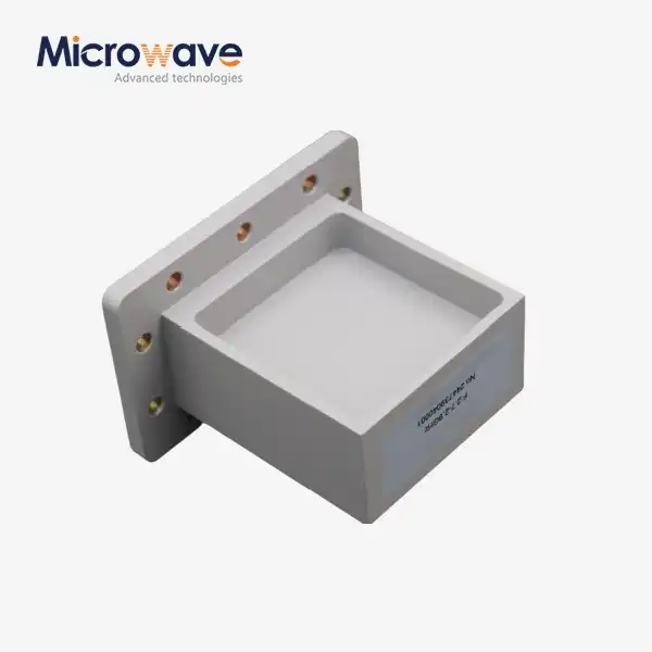 VIEW MORECustom WG to Coaxial Adapter
 VIEW MOREBroadwall Directional Coupler
 VIEW MOREHigh Power Waveguide Circulator
 VIEW MOREDigitally Controlled Phase Shifter
 VIEW MOREPoint Focusing Horn Lens Antenna
 VIEW MORELadder Membrane Conical Dual circular Polarization Horn Antenna
 VIEW MOREQuadrifilar Helix Antenna