





Common Mistakes When Specifying Waveguide Attenuators for Radar
Getting the specification right for waveguide attenuators in radar systems sounds straightforward — until a field failure tells you otherwise. In my experience working alongside defense contractors and telecom integrators, the root cause of most radar performance issues traces back not to design flaws, but to specification errors made during procurement. Waveguide attenuators control signal power levels within a transmission path, and even small mismatches in their specs can degrade radar sensitivity, damage hardware, or cause costly system downtime. This guide walks through the most common pitfalls and how to avoid them.
Understanding the Core Concepts of Waveguide Attenuators
How Attenuation Works in Radar Signal Chains
A waveguide attenuator lowers the signal's intensity by a set amount, measured in decibels (dB), without changing the shape of the pattern too much. In radar systems, this is used to keep critical receiver parts safe, check the transmit power, and check the signal routes. The part either takes or returns extra electromagnetic energy inside the waveguide structure, which keeps the flow of power in the system under control.
Key Performance Parameters to Know
Insertion loss, VSWR, and working frequency range are the three most important factors in choosing an attenuator. Insertion loss is a measure of how much signal energy a part absorbs beyond its rated attenuation value. Lower is better. Voltage Standing Wave Ratio (VSWR) tracks how signals are reflected at the component interface. In radar systems, a VSWR of more than 1.5:1 can lead to significant performance loss. Whether X-band (8–12 GHz), Ku-band (12–18 GHz), or Ka-band (26.5–40 GHz) radar is being used, the frequency range has to be dead on.
Fixed vs. Adjustable Attenuators: Which One Fits Your System?
Fixed attenuators have a set reduction value and are best used when power levels stay the same and are easy to describe. Adjustable (variable) attenuators let you change the signal level in real time, which makes them good for testing settings or adaptive radar systems. Passive designs are common for production hardware because they work well. Active attenuators are used in more specialized signal processing tasks where electronic control is needed, but they make the circuit more complicated.
Common Mistakes When Specifying Waveguide Attenuators for Radar Systems
Mistake 1: Mismatched Frequency Range
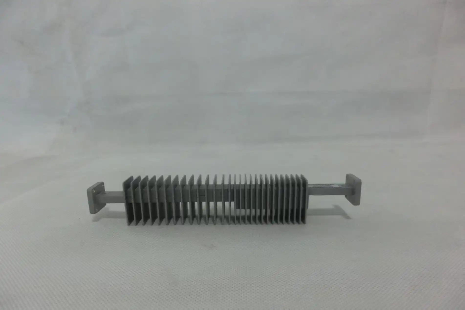
I see a lot of mistakes where people choose an attenuator rated for a frequency range that doesn't exactly match the radar's operating band. If a part is labeled for WR-90 (8.2–12.4 GHz), it won't work properly outside of that range. When used close to the ends of the band, insertion loss goes up randomly, and radar detection range goes down. Always make sure that the attenuator's rated frequency window covers your operating frequency plus a little extra on both sides.

Mistake 2: Ignoring Power Handling Limits
Radar emitters, especially burst systems, send out a lot of peak power that can quickly be more than an attenuator can handle. Engineers often get average power handling and peak power handling mixed up. For instance, a part that is rated for 10W average might only be able to handle 500W peak before the heat damages the resistive elements or causes an arc. Defense radar programs have had early field failures because they specified waveguide attenuators without taking peak pulse power into account.
Mistake 3: Confusing Attenuator Types
Waveguide, coaxial, and ferrite-based attenuators all do different things. Coaxial attenuators work well at lower frequencies and in small groups, but they have a bigger insertion loss above the X-band. People sometimes choose ferrite attenuators for symmetric attenuation jobs when they should really be used for non-reciprocal signal control. When you use the wrong type of attenuator, signal integrity problems happen that are hard to figure out after the attenuator is built into a circuit.
Mistake 4: Underestimating VSWR and Insertion Loss Tolerances
In order to lower unit cost, procurement teams sometimes agree to bigger tolerance bands. This is a choice that causes problems at the system level later on. On paper, an insertion loss limit of ±0.5 dB may seem fine, but in reality, cumulative variation can change system gain by ±5 dB across a 10-component signal chain. That has a direct effect on the minimum measurable signal (MDS) performance of radar devices. In the datasheet, you should always ask for test data and set tight tolerances.
Mistake 5: Skipping Installation and Calibration Checks
A failure cause that is often missed is improper flange torque during fitting. When you over-torque waveguide flanges, they deform the mating surface, which lets signal leakage through the gap. When you under-torque, contact is only made sometimes, which shows up in the field as random VSWR spikes. After installation, re-calibrating the signal chain makes sure that performance in the real world matches what was planned. This is an important step that is often skipped because of time constraints.
How to Avoid Specification Errors: Best Practices for Procurement and Engineering Teams
Define Technical Requirements Before Sourcing
Aligning engineering and procurement early on stops work from having to be redone later on. Make a list of the operating frequency, peak and average power levels, attenuation value, VSWR limit, insertion loss budget, and environmental requirements like temperature range and humidity exposure before sending out an RFQ. This becomes the standard by which to compare seller datasheets without just looking at price.
Verify Datasheets and Request Test Reports
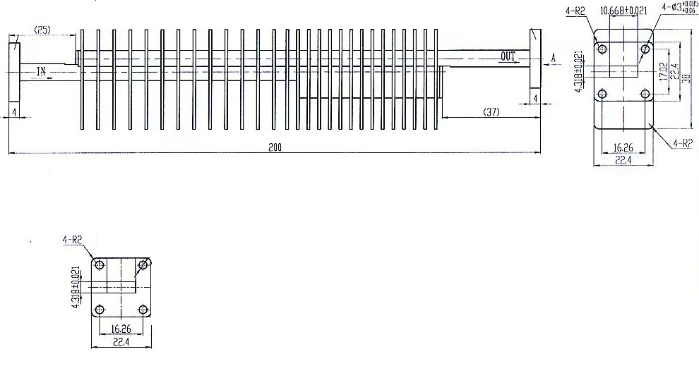
Not all datasheets show how well something actually works. Manufacturers of reliable waveguide attenuators give S-parameter test results (S11, S21) that can be linked to calibrated test tools. Instead of depending only on average values, ask for actual data. When checking out a new source, getting pre-production samples to test on your own test bench in-house adds a level of confidence that general datasheets can't give you.
Build Collaboration Between Procurement and Engineering
Structured joint reviews during the component selection stage, where both procurement and RF engineers look at the chosen parts together, greatly lower the chance of misspecification. Engineering gives you more detailed knowledge, and procurement gives you information about past suppliers, wait times, and how much things cost. The choice is better when looked at as a whole. When technical support teams from suppliers are called in early, they can often find design errors before an order is placed.
Comparison Guide: Choosing the Right Waveguide Attenuator for Radar Applications
To choose the right type, you have to match the technology limitations with the needs of the program. The main things to think about when making a choice are these:
- Waveguide attenuators vs. coaxial attenuators: Waveguide designs handle significantly higher power levels and exhibit lower insertion loss at microwave frequencies above 6 GHz. Coaxial types are compact and cost-effective for lower-frequency subsystems but are not recommended for high-power radar transmit paths.
- Fixed vs. variable attenuation: Fixed attenuators suit production radar hardware where signal levels are characterized and stable. Variable types are preferable in test setups, calibration benches, or adaptive systems requiring dynamic gain adjustment.
- High-frequency vs. standard waveguide bands: For millimeter-wave radar (35 GHz and above), precision-machined waveguide components with tighter dimensional tolerances are required. Standard X-band components are not dimensionally compatible with Ka- or W-band systems.
- Passive vs. active technologies: Passive attenuators are the default for most radar hardware due to their thermal stability and absence of bias circuitry. Active designs offer programmable attenuation but require power supply integration and add potential failure points.
High-frequency waveguide bands vs. normal waveguide bands: For millimeter-wave radar (35 GHz and above), waveguide parts that are precisely made and have tighter size limits are needed. Standard X-band parts don't fit into Ka- or W-band systems because of their different sizes.
Conclusion
It is common for specification mistakes to happen when buying waveguide attenuators, but they can be avoided. Mismatched frequency ranges, ignored power limits, choosing the wrong type of attenuator, accepting loose tolerances, and bad installation methods can all be fixed by conducting a thorough engineering study and working with the provider. If you get it wrong, you'll have to pay a lot more in returned gear, radar downtime, or failed system acceptance tests than you would have spent on proper design. The whole process is more reliable from the start if you work with a provider that gives you confirmed test data, customization choices, and quick technical help.
FAQ
What frequency ranges are waveguide attenuators available in for radar?
Waveguide attenuators are available across standard waveguide bands from L-band (1–2 GHz) through W-band (75–110 GHz). Common radar applications use X-band (WR-90), Ku-band (WR-62), and Ka-band (WR-28) components. Always match the waveguide size designation to your system's operating frequency.
How do I verify that a component meets my power handling requirements?
Check both average power and peak pulse power ratings in the datasheet. For pulsed radar, calculate peak power using pulse width and duty cycle. Request derating curves for elevated temperature operation, as power handling decreases at higher ambient temperatures.
Can waveguide attenuators be custom-designed for non-standard specifications?
Yes. Suppliers with in-house manufacturing and RF engineering teams can produce attenuators to custom attenuation values, flange types (UG, CPR, UBR), and frequency bands. Prototyping before full production orders is advisable for non-standard configurations.
What maintenance practices extend attenuator service life?
Inspect flange mating surfaces for corrosion or mechanical damage at scheduled intervals. Re-verify insertion loss and VSWR annually in operating systems. Store unused components with protective flange covers to prevent contamination of waveguide interiors.
Partner With ADM for Precision Waveguide Attenuator Solutions
Every part that ADM makes is based on more than 20 years of experience making things. We are a reliable source for waveguide attenuators for defense, aerospace, and satellite communication projects. Our goods are ISO 9001:2015-certified, and we offer fast prototyping and full engineering support. Ask our team for datasheets, samples, or a unique price right away. You can email us at craig@admicrowave.com to talk about your radar system needs right away.
References
1. Pozar, D. M. Microwave Engineering, 4th Edition. Wiley, 2011.
2. Skolnik, M. I. Introduction to Radar Systems, 3rd Edition. McGraw-Hill, 2001.
3. IEEE Std 521-2019. IEEE Standard Letter Designations for Radar-Frequency Bands. IEEE, 2019.
4. Montgomery, C. G., Dicke, R. H., & Purcell, E. M. Principles of Microwave Circuits. MIT Radiation Laboratory Series, McGraw-Hill, 1948. Reprinted by IET, 1987.
5. Rizzi, P. A. Microwave Engineering: Passive Circuits. Prentice Hall, 1988.
6. MIL-PRF-39010. Performance Specification: Resistors, Fixed, Film. U.S. Department of Defense, 2003.