


What is a coaxial directional coupler?
In modern RF and microwave systems, signal integrity can make or break critical operations. Whether you're managing satellite ground stations where signal degradation means lost data transmissions, operating radar systems where detection accuracy depends on precise power monitoring, or maintaining telecommunication networks where even minor signal losses impact performance, understanding coaxial directional couplers becomes essential. A Coaxial Directional Coupler is a passive four-port device that samples a predetermined portion of electromagnetic power traveling through a transmission line, enabling signal monitoring, measurement, and processing without disrupting the main signal path. This fundamental component ensures engineers can measure forward and reflected power, monitor transmission quality, and protect sensitive equipment across frequencies ranging from DC to millimeter-wave bands.
Understanding Coaxial Directional Coupler Fundamentals
The operational principle of a Coaxial Directional Coupler relies on electromagnetic coupling between two transmission lines positioned in close proximity within a coaxial structure. When RF energy passes through the main transmission line between the input port and transmitted port, a small fraction of this power couples to an adjacent transmission line, appearing at the coupled port. The coupling mechanism depends on the physical spacing between conductors, the dielectric material properties, and the frequency of operation. This coupling occurs directionally, meaning power flowing forward through the main line couples to the coupled port, while power flowing in the reverse direction couples to a separate isolated port in four-port configurations. The coaxial construction offers significant advantages over other coupler implementations. The enclosed structure provides excellent electromagnetic shielding, preventing external interference and radiation losses that plague open transmission line designs. Coaxial Directional Coupler assemblies maintain consistent impedance characteristics across wide frequency ranges, typically 50 ohms for most RF applications, ensuring proper matching with standard system components. The cylindrical symmetry of coaxial geometry produces uniform field distributions, contributing to predictable coupling behavior and superior directivity compared to planar structures. These attributes make coaxial directional couplers indispensable for applications demanding reliable performance in challenging electromagnetic environments.

Key Performance Parameters of Coaxial Directional Couplers
Coupling factor represents the primary specification, defined as the ratio of input power to coupled port power, expressed in decibels. A 20 dB Coaxial Directional Coupler couples one percent of the input power to the coupled port, allowing 99 percent to pass through to the transmitted port. Common coupling values include 10 dB, 20 dB, and 30 dB, selected based on application requirements for measurement sensitivity versus main line insertion loss. Tighter coupling values like 3 dB or 6 dB split power more evenly and find use in power division applications, while loose coupling values above 20 dB suit monitoring applications where minimal main line disturbance is critical. Directivity quantifies the coupler's ability to distinguish between forward and reverse power flow, calculated as the difference between coupling factor and isolation. High directivity ensures that power measurements accurately reflect the desired signal direction without contamination from reflections or reverse-traveling waves. Quality Coaxial Directional Coupler designs achieve directivity exceeding 30 dB across their operating bandwidth, meaning reverse-direction signals appear at least 30 dB lower at the coupled port compared to forward signals of equal magnitude. This parameter becomes crucial in applications like VSWR measurement and reflection coefficient determination, where separating incident and reflected signals determines measurement accuracy. Insertion loss describes power absorbed or dissipated within the coupler structure, reducing signal strength between input and transmitted ports. Premium Coaxial Directional Coupler designs minimize insertion loss through careful material selection, precision manufacturing, and optimized electromagnetic design. Typical insertion loss values range from 0.1 dB to 0.5 dB depending on coupling factor, frequency range, and power handling requirements. Lower insertion loss preserves signal strength for the primary transmission path, particularly important in systems where multiple couplers cascade or where overall system link budget constraints demand maximum efficiency.
Coaxial Directional Coupler Construction and Design Variations
Internal construction varies based on frequency range and performance requirements. Broadband Coaxial Directional Coupler designs employ coupled transmission line sections with specific length-to-wavelength relationships, often quarter-wavelength at center frequency, to achieve consistent coupling across multi-octave bandwidths. The coupled lines may use air dielectric for low-loss operation at microwave frequencies or PTFE-based dielectrics for compact size and mechanical stability. Manufacturing precision becomes critical as frequency increases; dimensional tolerances of micrometers determine coupling accuracy and directivity performance at millimeter-wave frequencies approaching 110 GHz. Port configurations distinguish three-port and four-port variants. Three-port Coaxial Directional Coupler models incorporate an internal terminating resistor at the isolated port, simplifying installation and ensuring proper directivity without requiring external termination. This configuration suits applications monitoring forward power only, common in transmitter output monitoring and amplifier gain measurement. Four-port designs provide access to both coupled and isolated ports, enabling simultaneous forward and reverse power monitoring. Bidirectional couplers combine two directional sections to independently sample forward and reverse signals, essential for VSWR measurement systems and network analyzer applications. Connector types and power handling capability reflect application environments. Low-power measurement applications utilize precision SMA connectors for frequencies extending to 40 GHz, offering repeatable performance and minimal VSWR contributions. Medium power applications employ N-type connectors supporting power levels to 500 watts average, suitable for base station monitoring and radar systems. High-power Coaxial Directional Coupler variants utilize 7/16 DIN or specialized airline connections for kilowatt-level broadcast and industrial heating applications, incorporating enhanced cooling features and high-voltage insulation. Material selection balances electrical performance, mechanical durability, and environmental resistance, with aluminum alloys for general purpose use and stainless steel for corrosive environments.
Coaxial Directional Coupler Applications Across Industries
Satellite Communication Systems
In satellite ground station installations, Coaxial Directional Coupler components enable continuous monitoring of uplink transmitter power without interrupting communication links carrying voice, video, and critical data streams. Engineers position couplers between high-power amplifiers and antenna feeds, sampling transmitted power for spectrum analyzer analysis, ensuring compliance with regulatory emission limits and preventing adjacent satellite interference. The coupled port connects to calibrated power meters providing real-time transmission level verification, alerting operators to degraded amplifier performance or antenna mismatch conditions before communication quality deteriorates. For C-band, Ku-band, and Ka-band satellite systems operating from 4 GHz to 40 GHz, precision Coaxial Directional Coupler designs maintain coupling accuracy within ±0.5 dB across temperature extremes and years of continuous operation. Receive path implementations employ loosely-coupled models to sample incoming signals for signal-to-noise monitoring and frequency verification without degrading weak satellite downlink signals. The minimal insertion loss characteristic of quality couplers, typically under 0.2 dB, preserves precious signal strength from satellites positioned 36,000 kilometers above Earth. Advanced satellite communication facilities utilize multiple Coaxial Directional Coupler stages in redundant configurations, ensuring uninterrupted monitoring capability even during maintenance activities. Integration with automated monitoring systems enables remote unmanned sites to report link health parameters via network connections, reducing operational costs while maintaining service reliability for telecommunications providers and government agencies.
Defense and Aerospace Radar Applications
Military and civilian radar installations depend on Coaxial Directional Coupler technology for transmitter protection and receiver sensitivity optimization. High-power radar transmitters generating megawatts of peak power require constant reflected power monitoring to prevent damage from antenna mismatch or environmental changes affecting antenna characteristics. Specialized high-power couplers sample forward and reflected signals, feeding protective circuits that automatically reduce transmitter power or disconnect from the antenna when dangerous VSWR conditions arise, protecting expensive traveling wave tube amplifiers or solid-state power modules worth millions of dollars. Airborne radar systems face additional challenges of weight, size, and vibration resistance that specialized aerospace-grade Coaxial Directional Coupler designs address through titanium construction, hermetic sealing, and shock-mounted connector interfaces. These compact, lightweight couplers operate reliably through aircraft maneuvers generating multi-G acceleration forces and temperature swings from ground-level heat to stratospheric cold during high-altitude missions. Modern phased array radar systems employ hundreds of individual Coaxial Directional Coupler units sampling each antenna element, providing data for sophisticated beamforming algorithms and fault detection systems that maintain operational capability despite element failures. Weather radar installations for meteorological forecasting and severe storm detection utilize environmentally-sealed coupler assemblies surviving years of rooftop exposure to wind, rain, and temperature cycling while maintaining calibration accuracy essential for quantitative precipitation measurement.
Telecommunication Infrastructure Networks
Cellular base station deployments incorporate Coaxial Directional Coupler components throughout the RF transmission chain for power monitoring, signal combining, and distributed antenna system applications. Macro cell towers serving multiple carrier frequencies employ couplers to split signals feeding different antenna sectors, with coupling values selected to balance power distribution across coverage areas accounting for terrain effects and subscriber density patterns. The wide frequency support of modern couplers spanning 698 MHz to 6 GHz accommodates legacy 2G services alongside current 4G LTE and emerging 5G New Radio frequencies without requiring separate components for each band. Indoor distributed antenna systems for office buildings, airports, and stadiums rely on networks of Coaxial Directional Coupler assemblies to distribute signals from fiber-fed remote radio heads throughout the coverage area. Engineers select coupling values from 6 dB to 20 dB based on distance from source equipment and desired signal strength at each antenna location, creating uniform coverage zones supporting thousands of simultaneous users. The high isolation between coupler ports prevents signals from one antenna from interfering with others, maintaining system stability critical for high-density venues during concerts, sporting events, or business conferences. Public safety distributed antenna systems supporting police, fire, and emergency medical communications deploy ruggedized Coaxial Directional Coupler units meeting strict passive intermodulation specifications below -153 dBc, ensuring reliable communications during crisis situations when lives depend on clear voice transmission.
Advanced Coaxial Directional Coupler Technologies and Future Developments
Millimeter-Wave and 5G Applications
The expansion of wireless communications into millimeter-wave frequency bands from 24 GHz to 110 GHz for 5G and future 6G networks drives development of advanced Coaxial Directional Coupler designs addressing propagation challenges unique to these frequencies. At millimeter wavelengths, manufacturing precision requirements tighten dramatically; coupling section dimensions of hundreds of micrometers require specialized machining capabilities and dimensional inspection techniques using laser measurement systems or coordinate measuring machines. Surface roughness effects that prove negligible at microwave frequencies introduce measurable losses at millimeter waves, necessitating electropolishing treatments and gold plating to minimize conductor resistance. Waveguide-to-coaxial transitions within millimeter-wave Coaxial Directional Coupler assemblies represent critical design elements, as impedance discontinuities at these interfaces generate reflections degrading directivity and VSWR. Engineers employ electromagnetic simulation software executing millions of calculations to optimize transition geometries, then verify designs through precision vector network analyzer measurements in anechoic chambers preventing external signal reflections from corrupting measurement accuracy. The resulting products enable 5G infrastructure developers to deploy millimeter-wave base stations, conduct propagation studies, and verify equipment performance as network operators build out high-capacity urban wireless networks supporting bandwidth-intensive applications like augmented reality, autonomous vehicles, and industrial automation.
Measurement System Integration
Modern test and measurement applications integrate Coaxial Directional Coupler technology with sophisticated signal processing to create comprehensive RF analysis solutions. Vector network analyzers employ precision couplers within their test ports to measure complex impedance, scattering parameters, and gain/phase characteristics of devices under test. The couplers separate incident and reflected signal components, feeding them to receivers computing reflection coefficient magnitude and phase through mathematical operations yielding Smith chart displays familiar to RF engineers. Calibration procedures account for directivity limitations, residual insertion loss, and connector imperfections, achieving measurement uncertainty below 0.1 dB across multi-octave frequency ranges. Spectrum analyzers utilize tracking generators with coupled outputs to implement scalar network analysis capability, sweeping frequency while measuring transmission or reflection response of filters, amplifiers, and antenna systems. The Coaxial Directional Coupler provides the reference signal path while the device under test receives the main signal path, with both signals feeding the analyzer's receiver through automatic switching circuits. Production testing facilities integrate automated test equipment employing multiple Coaxial Directional Coupler assemblies to simultaneously measure multiple parameters, achieving throughput rates of hundreds of devices per hour while maintaining measurement accuracy traceable to national standards laboratories. Electromagnetic compatibility testing for regulatory compliance employs specialized high-power couplers injecting controlled interference signals while monitoring device susceptibility, ensuring electronic products meet emission and immunity requirements before market release.

Selecting the Right Coaxial Directional Coupler for Your Application
Choosing appropriate Coaxial Directional Coupler specifications requires careful analysis of system requirements, operating conditions, and performance objectives. Frequency range determination comes first, as bandwidth requirements dictate coupling mechanism design and physical dimensions. Narrowband applications spanning single octaves or less permit optimized designs achieving superior directivity and flatter coupling response, while multi-octave requirements from DC to 40 GHz necessitate more complex coupling structures accepting some performance compromises across the full band. Power handling considerations follow, accounting for both average continuous power and peak power levels in pulsed applications like radar transmitters where instantaneous voltages may reach kilovolts despite modest average power levels. Environmental specifications including operating temperature range, humidity exposure, shock and vibration levels, and corrosion resistance determine mechanical design and material selection. Outdoor installations require weatherproof housings with gasket-sealed connector interfaces preventing moisture ingress that would degrade dielectric properties and corrode internal conductors. Aerospace applications demand lightweight construction using beryllium copper or titanium alloys meeting stringent flame resistance and toxicity regulations for aircraft interior installations. Connector type selection balances performance requirements against practical considerations of available mating cables, required power rating, and installation torque specifications. Custom Coaxial Directional Coupler configurations address unique requirements beyond standard catalog offerings, with experienced manufacturers providing engineering support for specialized applications in research, defense, and emerging technology fields.
Advanced Microwave Technologies Co., Ltd manufactures and designs a comprehensive line of RF and microwave coaxial directional couplers covering applications from DC to 110 GHz with coupling values from 10 dB to 30 dB. These precision instruments feature insertion loss below 0.2 dB, VSWR under 1.2:1, and isolation exceeding 30 dB across their operating bandwidth. Customers benefit from ISO 9001:2015 certified quality management systems ensuring consistent performance, RoHS environmental compliance, and comprehensive testing using state-of-the-art measurement equipment in our 24-meter microwave darkroom facility. Our engineering team provides technical consultation for custom frequency ranges, connector configurations, and power ratings meeting specific application requirements in satellite communications, defense systems, aerospace projects, and telecommunication infrastructure.
Conclusion
Coaxial Directional Coupler technology serves as the foundation for signal monitoring, measurement, and system protection across critical RF and microwave applications. Understanding their operating principles, performance parameters, and application-specific requirements enables engineers to specify optimal solutions ensuring reliable system operation and precise measurements.
Cooperate with Advanced Microwave Technologies Co., Ltd.
Advanced Microwave Technologies Co., Ltd stands as your trusted China Coaxial Directional Coupler manufacturer with over 20 years of manufacturing excellence. As a leading China Coaxial Directional Coupler supplier and China Coaxial Directional Coupler factory, we offer High Quality Coaxial Directional Coupler products at competitive Coaxial Directional Coupler prices. Our extensive inventory ensures Coaxial Directional Coupler for sale with immediate delivery for standard models, while our China Coaxial Directional Coupler wholesale programs provide volume pricing for system integrators and distributors. Our complete OEM services deliver custom frequency ranges, coupling values, materials, and connector types precisely matching your specifications, backed by ISO 9001:2015, ISO 14001:2015, and ISO 45001:2018 certifications demonstrating our commitment to quality, environmental stewardship, and workplace safety. Contact our experienced engineering team at craig@admicrowave.com to discuss your coaxial directional coupler requirements and receive technical consultation, detailed specifications, and competitive quotations for your next project.
References
1. Rizzi, Peter A. "Microwave Engineering: Passive Circuits." Prentice Hall. This comprehensive textbook covers directional coupler theory, design equations, and practical implementation techniques for coaxial and waveguide structures across microwave frequency ranges.
2. Pozar, David M. "Microwave Engineering, Fourth Edition." John Wiley & Sons. This authoritative text provides detailed analysis of coupled transmission line theory, scattering parameters, and directional coupler design methodologies used throughout the RF industry.
3. Collin, Robert E. "Foundations for Microwave Engineering, Second Edition." McGraw-Hill. This engineering reference examines electromagnetic coupling mechanisms, impedance matching techniques, and performance optimization approaches for microwave passive components including directional couplers.
4. Matthaei, George L., Leo Young, and E.M.T. Jones. "Microwave Filters, Impedance-Matching Networks, and Coupling Structures." Artech House. This classic engineering handbook documents design procedures for various coupler topologies with extensive tables and normalized design curves applicable to coaxial implementations.
YOU MAY LIKE
 VIEW MOREDouble Ridge Waveguide Bend
 VIEW MOREDouble Ridge Twist Waveguide
 VIEW MOREDouble Ridged WG To Coaxial Adapter
 VIEW MOREDouble-Ridged Waveguide Magic Tee
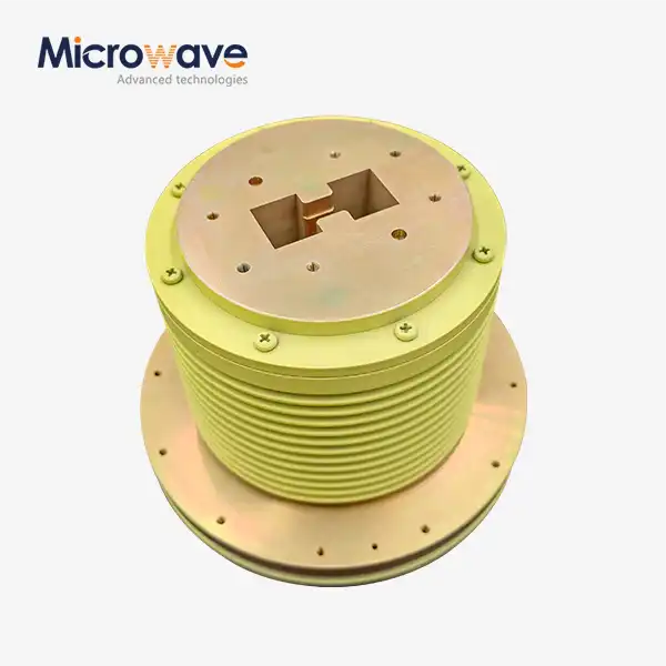 VIEW MOREDouble Ridge Waveguide Rotary Joint
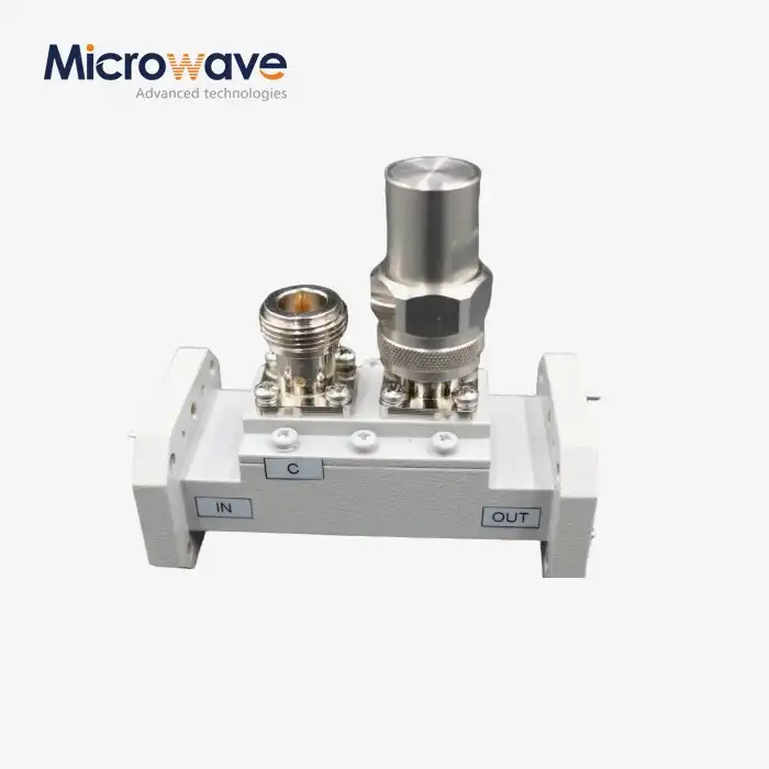 VIEW MOREDouble-Ridged Waveguide Loop Coupler
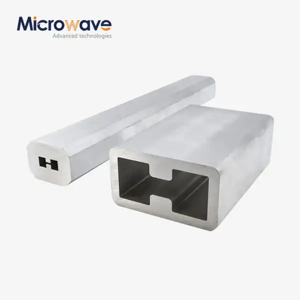 VIEW MOREDouble Ridge Waveguide Tube
 VIEW MOREPlastic Flange Caps
