





Waveguide Variable Attenuator Selection Guide: Key Specs Explained
Choosing the right waveguide variable attenuator is one of those decisions that seem straightforward until you're staring at a datasheet full of competing specs. A waveguide variable attenuator is a precision microwave component that controls signal amplitude within a waveguide transmission line — continuously adjustable, typically from 0 dB to 30 dB or beyond — without disrupting the signal path. Whether you're qualifying radar receivers, stress-testing a satellite ground station, or calibrating millimeter-wave test equipment, selecting the wrong unit can compromise your entire measurement chain. This guide walks through the specs that matter most.
Understanding Waveguide Variable Attenuators: Principles and Applications
How They Work — and Why It Matters
Basically, these devices work by adding a resistive dielectric vane into the electric field that is moving through the waveguide. The attenuation goes up as the vane moves deeper into the field and absorbs more energy. There are two main types of mechanical designs: the flap (vane) type and the rotary vane type. Based on Malus's Law, rotary vane designs move an absorbing element between two fixed attenuating sections. They offer very high accuracy (±0.1 dB or better) and phase stability, which makes them essential for calibrating vector network analyzers (VNAs).
Fixed attenuators give you a loss number that doesn't change. You can control things live and over and over again with variable designs, which is very important for situations where signal levels change quickly.
Where These Devices See Action
Most buyers don't realize how many different uses waveguide variable attenuators have at first. In professional settings, they are essential in the following ways:
- Radar system calibration: Precise attenuation control models target return signals at controlled power levels, letting the receiver's sensitivity be checked over dynamic ranges of more than 60 dB.
- Satellite communications testing: Engineers test satellite communications by simulating rain fade and free-space path loss conditions to make sure the link margin works in the worst-case situations before putting it into use.
- Defense electronics and EW systems: Ruggedized variable attenuators let you send controlled signals into electronic warfare and bugging devices while they are being tested at the bench level.
- Research and metrology labs: Universities and government labs use flexible microwave attenuators as their main reference standards when measuring high-frequency power.
All of these use cases have one thing in common: they need signal control that can be tracked and repeated in tough conditions.
Key Specs to Consider When Selecting a Waveguide Variable Attenuator
Frequency Range and Band Compatibility
The actual opening of waveguide variable attenuator components limits the frequency range that they can work with. The frequency range that can be used is directly related to the size of the waveguide. The WR-90 covers the X-band (8.2–12.4 GHz), the WR-28 covers the Ka-band (26.5–40 GHz), and the WR-10 covers the W-band (75–110 GHz). If you choose a unit that isn't in its intended band, it will cause cutoff losses and standing wave behavior that you can't predict. Before you buy, you should always make sure that the waveguide flange type (UG, CPR, etc.) and band name fit the interconnects in your system.
Attenuation Range, Resolution, and Insertion Loss
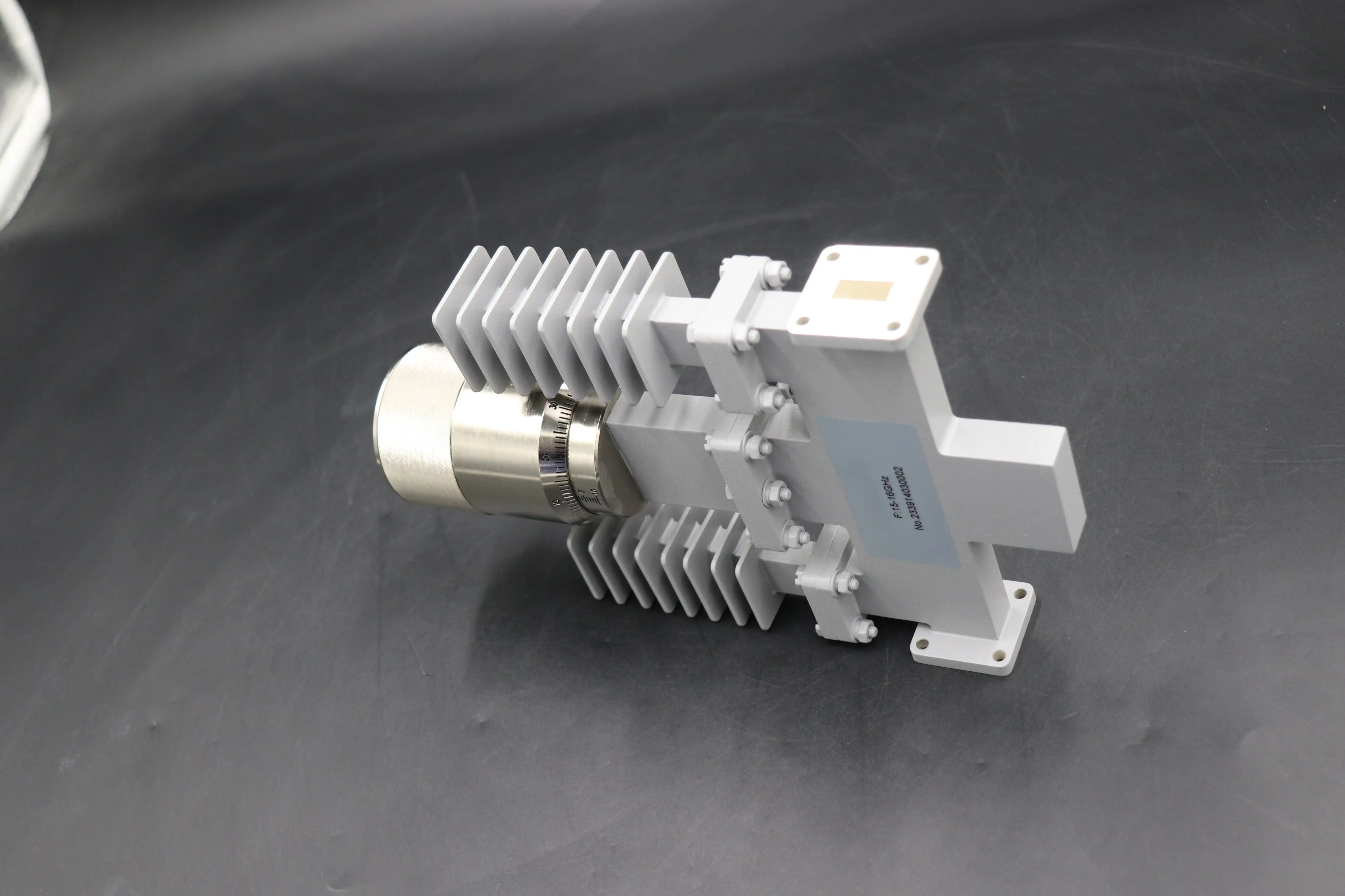
How much power you have over the sound is set by the dynamic range. Most lab-grade units have a range of 0 to 30 dB, and high-dynamic-range types can go up to 60 dB or more. In precision testing, resolution, or the smallest step that can be repeated, is very important. Designs that are driven by micrometers can often reach 0.01 dB resolution, which is much higher than what direct-reading drum-scale models can do. At a setting of 0 dB, residual insertion loss should ideally stay below 0.5 dB. This keeps the system efficient when attenuation is not needed.
Power Handling, VSWR, and Construction Robustness
In high-power or fielded settings, these specs can often tell the difference between a waveguide variable attenuator that works well and one that doesn't:
- Average power handling depends on how well the resistive element can get rid of heat. This is very important for continuous wave (CW) applications where the vane needs to keep absorbing energy without breaking down.
- Peak power handling defines the voltage breakdown threshold inside the waveguide. This is the most important number for pulsed radar duty cycles, where instantaneous power can reach kilowatts.
- VSWR should stay below 1.15:1 as the attenuation range widens so that harmful signal reflections don't happen back toward amplifiers or sources that are sensitive.
- Construction standards for defense-grade uses typically follow MIL-DTL-3933, which mandates robustness in harsh environments with temperature changes, shocks, and vibrations common in aircraft systems.
When buying for mission-critical projects, procurement engineers should ask for full test data, not just average values. You should expect datasheets from all reputable manufacturers that show measured insertion loss and VSWR across the whole frequency range.
Comparing Waveguide Variable Attenuators to Other Attenuator Types
Knowing the pros and cons of different attenuator technologies helps keep expensive gaps between what the component can do and what the application needs.
Fixed attenuators have no moving parts and offer stable, repeatable loss. They work great for impedance matching pads and bias decoupling networks, but are useless when dynamic control is needed. Coaxial variable attenuators work well with a wider range of connectors and lower frequencies, but they have problems with heat and have high insertion loss at millimeter-wave frequencies, where waveguide designs do better. When it comes to automatic test routines, PIN diode attenuators are useful because they can switch electronically quickly. However, their linearity decreases at high power, and they cause more phase variation than rotary vane mechanical designs.
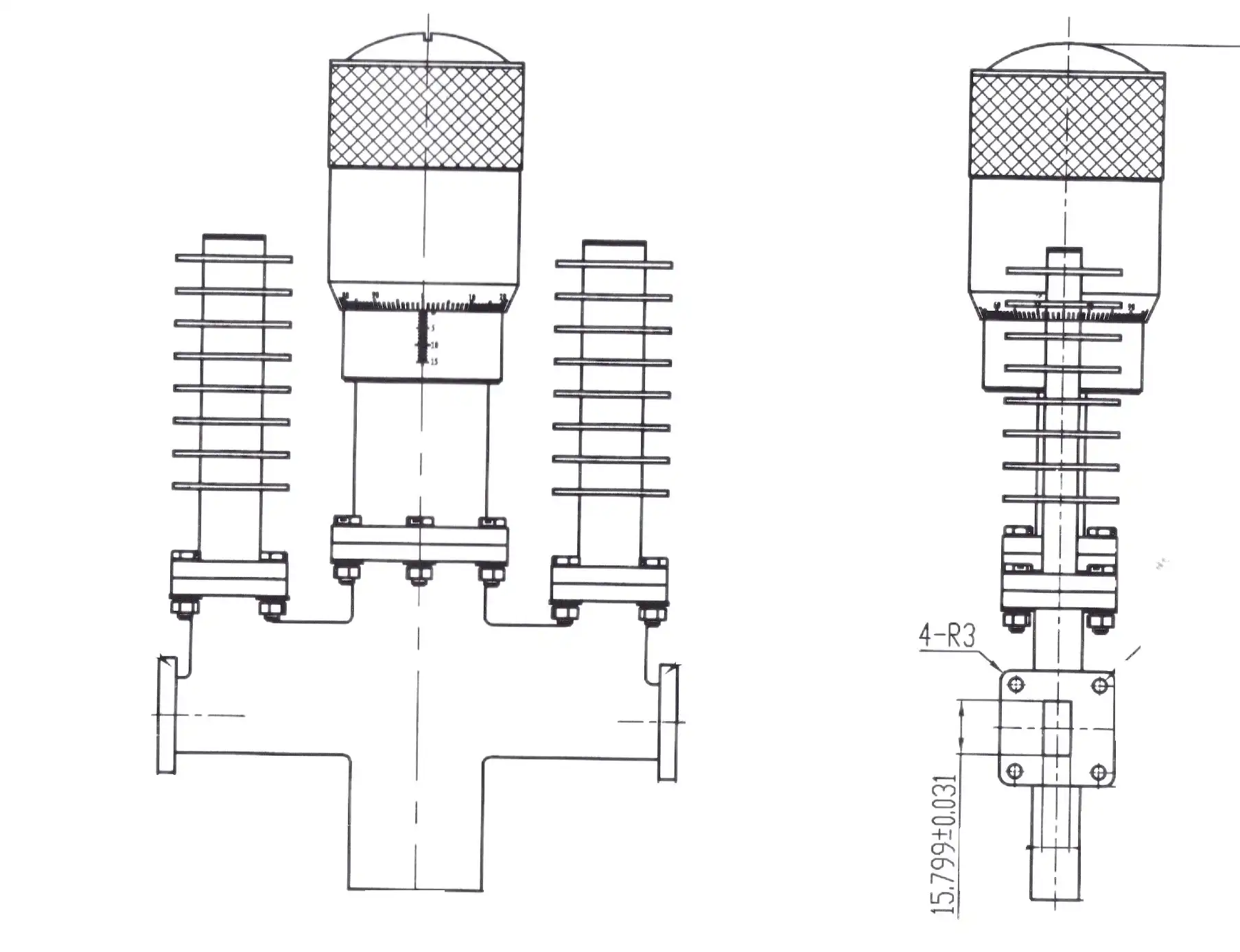
In real life, mechanical waveguide variable attenuators are still the best choice when your application is above Ku-band, needs to handle kilowatt-class power, or needs to be able to repeatably achieve sub-0.5 dB residual insertion loss. PIN diode or step attenuator configurations may be enough for sub-6 GHz automated switching with moderate power.
Procurement Considerations for B2B Buyers
Getting waveguide variable attenuators for mass production is very different from getting them for a single lab setup. Standard stock items usually have lead times of four to eight weeks. Custom designs, such as changed flanges, non-standard frequency bands, or motorized actuator integration, can take twelve weeks or longer. If a procurement team is in charge of a program that lasts more than one year, they should start negotiating blanket purchase deals early.
The review of suppliers should go beyond the store page. Buyers should carefully check to see if the manufacturer is ISO 9001:2015 certified, can provide full documentation on how the materials were made, and offers technical support after delivery. When parts are used in live systems, warranty terms and repair/recalibration services are just as important as the unit price itself.
Motorized and programmable versions deserve a specific call-out: for Automated Test Equipment (ATE) settings, waveguide attenuators with stepper motors and GPIB, USB, or Ethernet interfaces allow script-controlled attenuation sweeping, which gets rid of the chance of making mistakes when adjusting them by hand and greatly speeds up test throughput.
Conclusion
To choose the correct adjustable waveguide variable attenuator, you need to make sure that the physical band parameters, dynamic range, power handling ratings, and building standards are all right for the purpose. For accurate metrology, rotary vane shapes give the best accuracy and phase stability. The dynamic range of flap-type designs is good for general lab use and doesn't cost too much. Automation can start with motorized configurations. No matter what you need, the chance of buying something is greatly reduced when you work with an expert seller who offers full documentation, traceable quality standards, and quick technical support.
FAQ
What frequency bands do waveguide variable attenuators cover?
Waveguide band names are directly linked to standard units. For example, WR-90 is for X-band, WR-62 is for Ku-band, WR-28 is for Ka-band, and so on, all the way down to WR-10 for W-band (75–110 GHz). The ADM can measure up to 110 GHz, which is almost the whole microwave and millimeter-wave range.
Can these attenuators be used in pulsed radar systems?
In that case, the safety factor is the highest power number, not the average power. Waveguide designs handle kilowatt-class peak power far more reliably than coaxial equivalents because the air-dielectric waveguide chamber removes the risk of center-conductor arcing.
What calibration approach is recommended for high-accuracy work?
Inspections using a VNA are usually done on a regular basis. Check the VSWR and insertion loss over the whole frequency range to find damaged or contaminated resistive vanes. Micrometer-driven waveguide variable attenuators need a calibration chart that shows how the mechanical position is related to the absorption value in decibels.
Are motorized versions available for automated test environments?
Yes. For ATE integration, programmable motorized versions with stepper motors and GPIB/USB/Ethernet interfaces are common. These allow for high-repeatability attenuation sweeping that is managed remotely by scripts.
Partner with ADM for Precision Waveguide Variable Attenuator Solutions
For more than 20 years, ADM has sold high-precision waveguide variable attenuators to companies in the defense, space, and research industries around the world. Our production method is ISO 9001:2015-certified; all of the materials can be tracked, and we can measure up to 110 GHz in-house, so you can be sure that every unit works as it should. As usual, you get custom settings, OEM documentation, and quick expert help. Reach our engineering team directly at craig@admicrowave.com to explore our product range and request a quote.
References
1. Pozar, D. M. — Microwave Engineering, 4th Edition, Wiley, 2011.
2. IEEE Std 474 — Specifications and Test Methods for Fixed and Variable Attenuators, IEEE, 2000.
3. MIL-DTL-3933 — Detail Specification: Attenuators, Fixed and Variable, Radio Frequency, U.S. Department of Defense, 2007.
4. Marcuvitz, N. — Waveguide Handbook, IEEE Electromagnetic Waves Series, Peter Peregrinus Ltd., 1986.
5. Keysight Technologies — Microwave Component Measurement Application Note 95-1, Keysight Technologies, 2019.
6. Montgomery, C. G., Dicke, R. H., & Purcell, E. M. — Principles of Microwave Circuits, MIT Radiation Laboratory Series, McGraw-Hill, 1948.
