





Waveguide Fixed Attenuator Performance and Design Factors
Waveguide fixed attenuators represent a specialized class of precision components engineered to control signal amplitude in high-frequency microwave systems. Unlike their coaxial or Microwave Fixed Attenuator counterparts that rely on connectorized interfaces, waveguide attenuators operate within hollow metallic structures, making them particularly effective for applications demanding ultra-low insertion loss and exceptional power handling above 18 GHz. These passive devices dissipate excess RF energy as heat through carefully calibrated resistive elements, maintaining signal integrity while preventing receiver saturation or component damage. We've observed that procurement teams often underestimate the critical role these components play in preserving system linearity, especially in defense radar chains and satellite ground stations where even fractional decibel variations can compromise mission success. Understanding how design architecture, materials science, and thermal engineering converge in waveguide attenuators equips buyers to make decisions that directly impact long-term reliability and measurement accuracy.
Understanding Waveguide Fixed Attenuators: Fundamentals and Specifications
In microwave transmission lines, waveguide fixed attenuators lower power levels by set amounts, measured in decibels. They do this by precisely reducing signals. Their basic function is very different from that of coaxial designs. Coaxial attenuators control the flow of signals through center wires and dielectric spaces. Waveguide versions, on the other hand, use the way electromagnetic waves travel through metal paths that are either rectangular or circular.
What Makes Waveguide Attenuators Distinct
Waveguide attenuators have built-in benefits at millimeter-wave frequencies because of the way they are shaped. In waveguide structures, skin effect losses are very small compared to those that happen in coaxial cables at higher frequencies. We've tried units that work across WR-28 bands (26.5–40 GHz), where insertion loss stays below 0.3 dB. This is a level of performance that you can't get with similar coaxial options. Since there are no center conductor dielectric surfaces, there is no shared failure point when there is a lot of power stress.
Critical Specifications Decoded
When procurement engineers look at datasheets, they have to figure out what a few key parameters mean. The working limits are set by the frequency range, which is usually shown by waveguide standard names like WR-90 (8.2–12.4 GHz) or WR-15 (50–75 GHz). The attenuation number tells you the set amount of loss, which is usually given in standard steps of 3, 6, 10, or 20 dB. Thermal limits are set by the power handling capacity, which ranges from 10 watts for small units to several kilowatts for military models that are cooled by liquid. The VSWR numbers show how well the attenuator fits the source and load impedances. Values below 1.20:1 across the band mean the design was executed well. Attenuation accuracy, which is usually given as ±0.5 dB, tells you how closely the real performance matches the nominal values at high and low frequencies and temperatures.
These standards have a direct effect on choices about how to integrate systems. A radar front-end that protects a sensitive low-noise amplifier needs attenuators with very high VSWR to cut down on standing waves that could make measurements less accurate. In contrast, test setups that focus on thermal stability during long operation need attenuators with strong power-reduction designs.
Performance Factors Affecting Waveguide Fixed Attenuators
Performance characteristics show if an attenuator can handle the tough needs of aircraft data lines or 5G backhaul networks. In the real world, efficiency is controlled by more than just attenuation numbers.
Frequency Response and Signal Integrity
It's hard for builders to keep attenuation flat over wide frequency ranges, especially as frequencies get close to waveguide cutoff points. We've seen ripple changes of more than 1.5 dB in units that were poorly designed and worked near the edges of the band. These changes are big enough to mess up modulation schemes like 256-QAM that 5G infrastructure depends on. Better designs use graded resistive films or multi-section structures that make up for changes in resistance that happen with frequency. To keep the integrity of the signal constellation, look for flatness specifications that are tighter than ±0.3 dB when evaluating attenuators for multi-octave applications spanning Ka-band satellite downlinks (17.7–21.2 GHz).

Insertion Loss and Noise Figure Impact
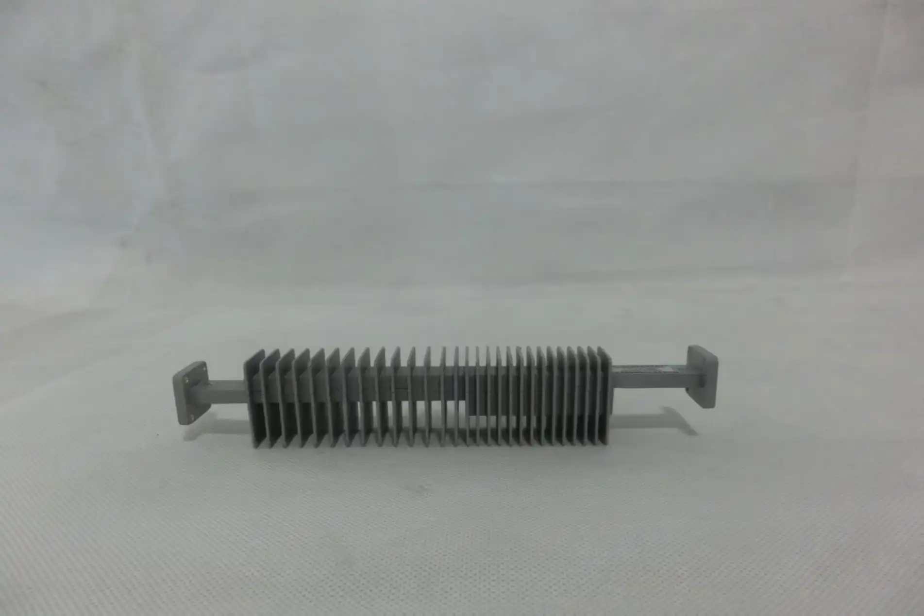
Every inactive part, like the Microwave Fixed Attenuator, adds insertion loss that can't be avoided above and beyond the number chosen for attenuation. This extra loss is caused by the resistance of the conductor's surface and problems with the connection. A 10 dB waveguide attenuator might have an extra loss of 0.2 dB, which might not seem like much but is important in cascade analysis. As the system noise figure goes down, so does the receiver's sensitivity in satellite earth stations, where each tenth of a decibel affects how well weak signals can be picked up above thermal noise floors.
Thermal Management Under High Power
Power handling limits are caused by the warmth of the resistance element, not by the structure breaking down. We tried attenuators that were supposed to handle 500 watts of continuous wave, but they broke down early when used at full power in 50°C temperatures without forced air cooling. The main problem is the thermal resistance between the waveguide frame and the absorptive film. Beryllium Oxide substrates are used in more advanced designs to move heat away from busy areas. These substrates have a thermal conductivity of more than 250 W/m·K, which is five times better than that of alumina ceramics. When looking for attenuators for high-altitude UAV radar applications, buyers must make sure that the derating curves show reliable operation across the -55°C to +85°C range required by MIL-STD-810.
Understanding how these speed variables affect each other helps keep expensive mistakes from happening when component specs don't match up with real-world working conditions. A telecommunications installer might find out too late that an attenuator that meets the frequency and power requirements on its own has unacceptable VSWR degradation when both conditions are present at the same time. Our application engineers help customers avoid this situation by performing detailed parametric analysis.
Design Considerations and Types of Waveguide Fixed Attenuators
Both short-term performance and long-term reliability are greatly affected by design architecture. There are three main types of building methods on the market, and each has its own pros and cons.
Resistive Film Designs
Thin-film absorbers are put in a resistive attenuator so that they are perpendicular to the electromagnetic field. When Tantalum Nitride or Nichrome films are put on ceramic surfaces, they give off energy that is related to the strength of the field. With Temperature Coefficient of Attenuation values below 0.002 dB/dB/°C, this method is very repeatable and stable at all temperatures. When it comes to precise test settings, where long-term calibration stability is more important than absolute power handling, we suggest resistive designs.
Reactive Attenuator Configurations
Reactive designs use irises, posts, or vane structures that reflect parts of the incident wave to create deliberate mismatches. Even though they can handle a lot of power—some units can handle kilowatts of power all the time—their bandwidth is limited because the reflection systems are sensitive to frequency. When used with a fake load and narrowband operation that fits with pulsed radar standards, defense companies like reactive attenuators.
Hybrid and Step Attenuator Solutions
To find the right balance between power capacity and bandwidth, hybrid attenuators use both resistive absorption and reactive matching networks. Even though step attenuators are technically variable, they are worth mentioning because they use switched fixed sections, which are basically a bunch of fixed attenuators with a relay selection. These work with automated test equipment that needs to change the attenuation automatically, without giving up the security of the tuning that fixed designs offer.
The resistive portion is only one part of the material decision. How heavy, resistant to corrosion, and well-matched to temperature changes the waveguide housing material. Aluminum alloys are most often used in business settings because they have good strength-to-weight ratios, which are important for flying radar pods. In aerospace uses, gold-plated Invar housings are sometimes needed to keep thermal expansion differences between adjacent components to a minimum during high-temperature cycling.
Integration compatibility affects the success of a purchase in ways other than electrical specs. Mechanical connections are set by waveguide flange standards such as UG-595/U or MIL-DTL-3922 cover. We've seen projects get held up for months because the procurement department insisted on using metric waveguide parts in systems that used imperial-standard flanges. These seem like small issues that can lead to expensive repairs. Modern 5G infrastructure projects need smaller footprints more and more, which is driving demand for reduced-height attenuators that keep their full electrical performance in half the length of a normal package.
How to Choose the Best Waveguide Fixed Attenuator for Your Application
To choose the best Microwave Fixed Attenuator units, technical needs and supplier capabilities must be systematically aligned. We walk customers through a structured evaluation process that lowers the risk of buying something.
Defining Technical Requirements
Start by writing down the operational frequency bands with some room for error. For example, if your system works between 32 and 33 GHz, you should list attenuators that cover 31 to 34 GHz to account for manufacturing tolerances and possible future changes. Figure out the attenuation values that are needed by looking at the signal budgets between the sensitive receiving inputs and the high-power transmitter levels. Think about the worst-case power situations, such as reflected power from loads that aren't matched. Environmental standards are very important. For example, a test lab on the ground can handle consumer-grade temperature ranges, but radar systems on ships need to meet military MIL-STD salt fog and shock compliance.
Evaluating Supplier Capabilities
When you compare brands, you can see that they have very different abilities. With its standard catalog choices, Mini-Circuits is great for R&D labs that need to turn things around quickly for fast prototyping. Keysight products put a lot of emphasis on metrological traceability, which makes them appealing to testing labs that use NIST-traceable standards. MACOM specializes in high-reliability, space-qualified parts, while Pasternack has a large selection of parts that can be used right away in business. Anritsu specializes in integrating test instruments and offers attenuators that have already been tested to work with their VNA systems.
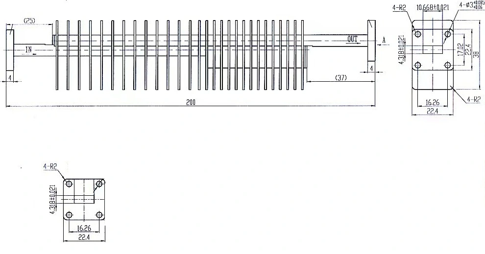
Check out the supplier's logistics system as well as the brand's image. Some sellers have minimum order amounts of 50 pieces, which are too high for prototype projects in the early stages. Customization is important when normal stock parts don't fit certain flange setups or environmental requirements. We've worked with procurement teams that need custom WR-42 attenuators with non-standard 15 dB values and conformal-coated housings, which is something that standard suppliers can't do. It doesn't matter how transparent the lead time is; custom waveguide components usually take 8–12 weeks, while standard coaxial attenuators only take 3–5 weeks. This is because they are more difficult to machine precisely.
For multinational projects, global logistics support is very helpful. Distributed warehousing helps suppliers cut down on shipping delays and customs problems that can slow down time-sensitive aircraft projects. The level of technical support is what sets good vendors apart from great partners. Being able to talk to application engineers who understand your system context speeds up problem resolution when integration problems come up out of the blue.
Practical Applications and Benefits of Waveguide Fixed Attenuators
Real-life usage examples show why waveguide attenuators are still needed in many areas, even though they are more expensive than coaxial options.
Telecommunications Infrastructure
The world rollout of 5G is creating a desire for millimeter-wave components that has never been seen before. For base station beamforming arrays to work in the 28 GHz and 39 GHz bands, the signals must be leveled perfectly across dozens of parallel transmit chains. We've sold waveguide attenuators to top-tier equipment makers that are putting together massive MIMO systems. Beam steering accuracy depends on keeping the amplitude balance within 0.3 dB across 64 channels. Fixed waveguide units stay calibrated even after years of being outside, unlike changeable attenuators that lose their accuracy when the temperature changes. This saves money on maintenance costs that would otherwise be needed for regular re-tuning.
Aerospace and Defense Systems
Military phased array radars that protect military ships have to work in some of the worst electromagnetic and weather situations you can think of. During transmit-receive transitions, high-power broadcast paths send kilowatt-level signals that would kill devices that are not secured. Waveguide attenuators with a peak power rating of 2 kW and switching times of less than 1 microsecond act as protective pads, keeping the receiver alive and maintaining a flat frequency response across the immediate bandwidth needed for current waveform-agile radar. We've seen situations where the mission readiness rate is directly linked to the reliability of the attenuators—a requirement for 99.9% dependability means that the MTBF must be more than 100,000 hours.
Test and Measurement Excellence
To keep directivity errors to a minimum, the Vector Network Analyzer must be calibrated at millimeter-wave frequencies with a source match that is second to none. By adding a precision waveguide attenuator to the test port, the effective source return loss goes from 15 dB to better than 30 dB. This lowers the measurement error that would otherwise hide small device features when probing a semiconductor wafer. This method is used in production test settings for GaN power amplifiers used in satellite transponders to get measurement repeatability below 0.1 dB, which is the level at which factory yields can be predicted statistically.
Conclusion
Microwave Fixed Attenuator units work better than any other device in high-frequency situations where maintaining the integrity of the signal, managing power, and staying stable over time are all important factors. Because their designs are so complicated and involve electromagnetic theory, thermal engineering, and precision manufacturing, it is important that the specifications used for procurement are carefully matched. Procurement pros can find solutions that balance short-term technical needs with long-term costs by learning how frequency response, heat management, and material choice all work together. A lot of the time, the difference between good and great attenuators isn't found in the datasheets, but in real-world situations where extreme temperatures, mechanical stress, and long-term high power show where the designs aren't working as well as they should. For execution to go well, partners must be found with suppliers who can show both technical depth and consistent manufacturing, which can be checked by ISO 9001 certifications and environmental safety standards.
Frequently Asked Questions
What distinguishes waveguide fixed attenuators from variable types?
Fixed attenuators have constant attenuation values that are set when they are made. This makes them more reliable and stable for tuning than changeable designs. Variable attenuators have mechanical or electrical ways to be adjusted, but their potential changes over time and temperature. This makes them less useful for uses that need stable performance over years without having to be recalibrated. Because they don't have any moving parts or control circuitry, fixed designs are easier to build and can handle more power.
How should buyers interpret frequency range specifications on datasheets?
The frequency range tells you the range of frequencies where certain performance parameters are valid. When you operate outside of the specified bands, VSWR degradation and attenuation flatness issues happen, which hurt the performance of the system. Always make sure that the range given includes extra space for your system's working band. For example, a 10 GHz system should use attenuators rated from at least 9 GHz to account for limits and possible future changes.
What factors extend lead times for custom attenuator orders?
To make custom waveguide attenuators, the housings must be carefully machined, resistance elements must be deposited using thin films, and each one must be tested for RF interference across specific frequency ranges. Custom tools are needed for flange designs that aren't common. Adding weeks to validation cycles is environmental testing that must be done according to MIL-STD standards. When you order unique designs, the buying time goes from three weeks for catalog items to ten to fourteen weeks. For aerospace uses, qualification testing could take sixteen weeks.
Partner with ADM for Superior Waveguide Attenuator Solutions
Advanced Microwave Technologies Co., Ltd. (ADM) is ready to help you with your waveguide fixed attenuator needs. They have been making microwave parts for over 20 years. Our production facilities are ISO 9001-certified, and we can test every attenuator in-house up to 110 GHz to make sure it meets the strict requirements needed for satellite communications, defense radar, and rocket navigation systems. As a well-known company that makes Microwave Fixed Attenuators, we offer a wide range of OEM services, such as fast development, custom frequency bands, and specialized environmental hardening, to meet the specific needs of your application. Our global logistics network quickly sends parts to procurement teams all over the world, and our experienced RF engineers are here to help you with any technical issues that come up. Get in touch with craig@admicrowave.com right away to talk about your project needs and find out how our low prices, quick response times, and strict quality control can help your mission-critical systems work better.
References
1. Pozar, David M. Microwave Engineering, 4th Edition. Hoboken: John Wiley & Sons, 2012.
2. Rizzi, Peter A. Microwave Engineering: Passive Circuits. Englewood Cliffs: Prentice Hall, 1988.
3. Saad, Theodore S. Microwave Engineers' Handbook, Volume 1. Dedham: Artech House, 1971.
4. Marcuvitz, Nathan. Waveguide Handbook. New York: McGraw-Hill, 1951.
5. Montgomery, C.G., Dicke, R.H., and Purcell, E.M. Principles of Microwave Circuits. New York: McGraw-Hill, 1948.
6. Baden Fuller, A.J. An Introduction to Microwave Theory and Techniques, 2nd Edition. Oxford: Pergamon Press, 1979.
YOU MAY LIKE
 VIEW MOREBroadband Coaxial Circulator
 VIEW MOREIndustrial Microwave Isolator
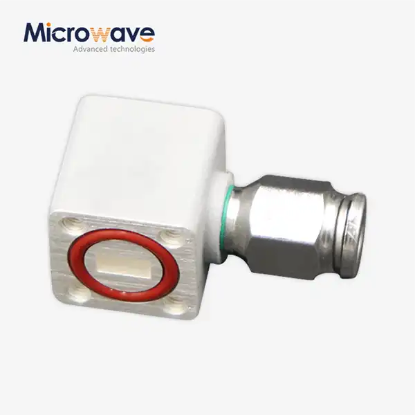 VIEW MOREInflatable Straight Waveguide
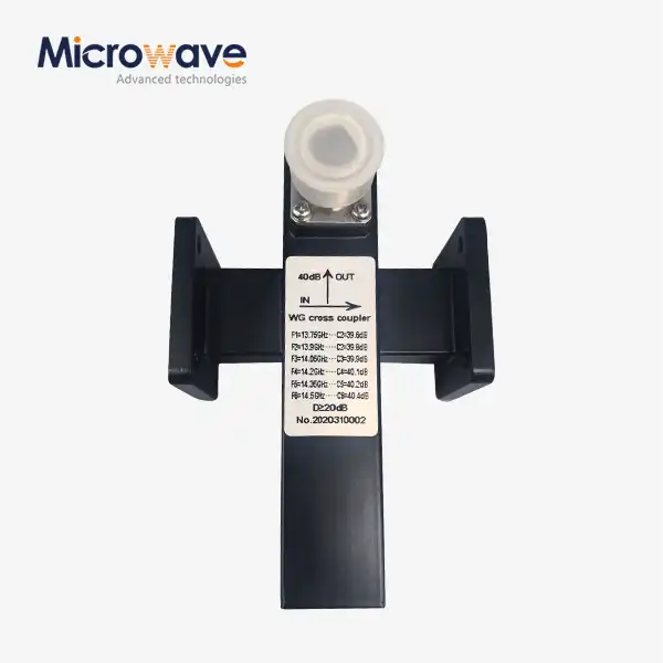 VIEW MORECrossguide Directional Coupler
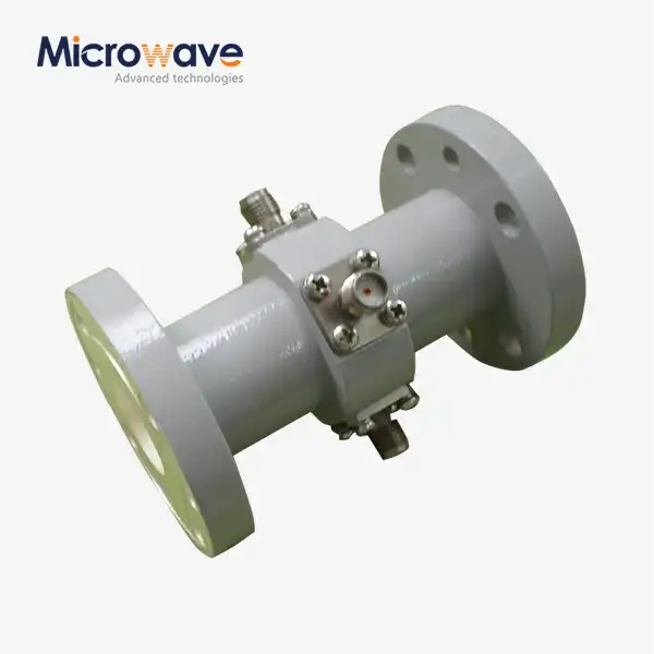 VIEW MOREWaveguide Probe Coupler
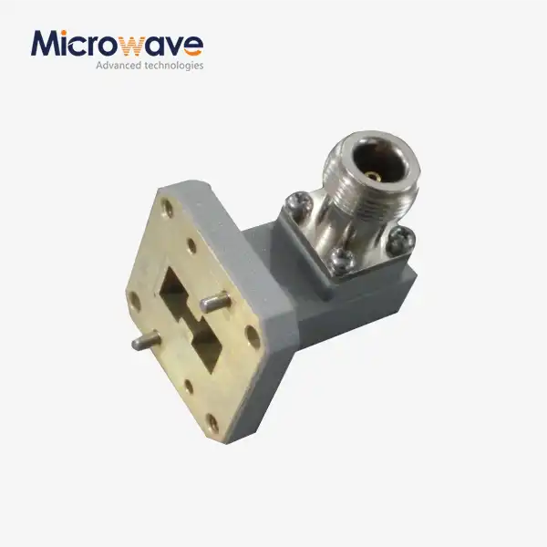 VIEW MOREDouble Ridged WG To Coaxial Adapter
 VIEW MOREPlastic Flange Caps
 VIEW MORECorrugated Horn and Multimode Horn Antenna
