Stepped Impedance vs Corrugated Waveguide Low Pass Filter Trade-Offs
Procurement teams have to make tough decisions about the pros and cons of both stepped impedance and corrugated waveguide low-pass filter designs. These decisions affect the performance, cost, and long-term dependability of the system. Stepped impedance designs use distinct impedance changes along the waveguide path to create frequency-selective rejection. They have small footprints and are easy to make. Periodic grooves or ridges in corrugated designs change the way electromagnetic fields are distributed, which improves stopband rejection and power handling. By knowing these basic differences, engineers and procurement managers can choose filters that meet the needs of specific applications while also meeting the needs for cost-effectiveness and integration.
Understanding Waveguide Low Pass Filters: Fundamentals and Design Principles
Waveguide low-pass filters are important passive parts in microwave architectures because they control the spectrum by letting signals below a certain cutoff frequency through while blocking unwanted harmonics and spurious emissions. These gadgets use the way electromagnetic waves naturally move through hollow metal tubes, where they travel in distinct modes that are set by the waveguide's shape and frequency.
Stepped Impedance Architecture
Stepped impedance designs achieve frequency selection by switching between parts with different cross-sectional sizes. Each change creates a reflection coefficient that, when properly phased across several stages, blocks frequencies that aren't wanted. As part of the design process, section lengths and impedance ratios are worked out using Chebyshev or Butterworth polynomial responses, with passband flatness and stopband steepness being balanced. Precision milling or casting of aluminum or brass is usually used to make these filters. They are then silver-plated to reduce insertion loss. Because this shape is simple, it means shorter production cycles and simpler tools. This makes stepped impedance filters a good choice for projects that need to be finished quickly or on a budget.
Corrugated Filter Topology
Corrugated waveguide low-pass filters have grooves that are machined at right angles to the direction of propagation. These grooves create capacitive and inductive elements that change the frequency response. Cutoff characteristics and stopband attenuation are directly affected by the depth, width, and spacing of the grooves. Engineers can get rejection levels above 60 dB at harmonic frequencies by using advanced electromagnetic simulation tools like HFSS or CST Microwave Studio to fine-tune these settings. The corrugated structure naturally spreads current concentration more evenly than sudden changes in impedance. This means that it can handle more power, which is very important in transmitter applications that need to pass kilowatt-level continuous wave signals or megawatt peak pulses without arcing. Choosing the right material is often like choosing a stepped impedance design, but there may be stricter surface finish rules to follow to keep the loss low across the passband.
Noise Suppression and Signal Integrity
Both types of filters make a big difference in the quality of the signal at the system level by getting rid of unwanted spectral components that are caused by nonlinearities in amplifiers or frequency converters with waveguide low-pass filters. Unwanted harmonics can mess up nearby communication lines, go beyond the limits set by regulators, or cause false warnings in radar processing chains if they are not stopped. During specification, the attenuation slope and ultimate rejection level are very important measurements that have a direct effect on the accuracy of measurements in test tools and the transmission range in real-world systems. To keep standing waves from making amplifiers less efficient, procurement teams should ask for S-parameter data across the whole working span and make sure that return loss stays below the specified levels.
Trade-Off Analysis: Stepped Impedance vs. Corrugated Waveguide Low-Pass Filters
When picking between these two waveguide low-pass filter architectures, you have to think about a lot of performance factors and practical issues that affect the total cost of ownership and the success of the operation.
Frequency Response and Insertion Loss
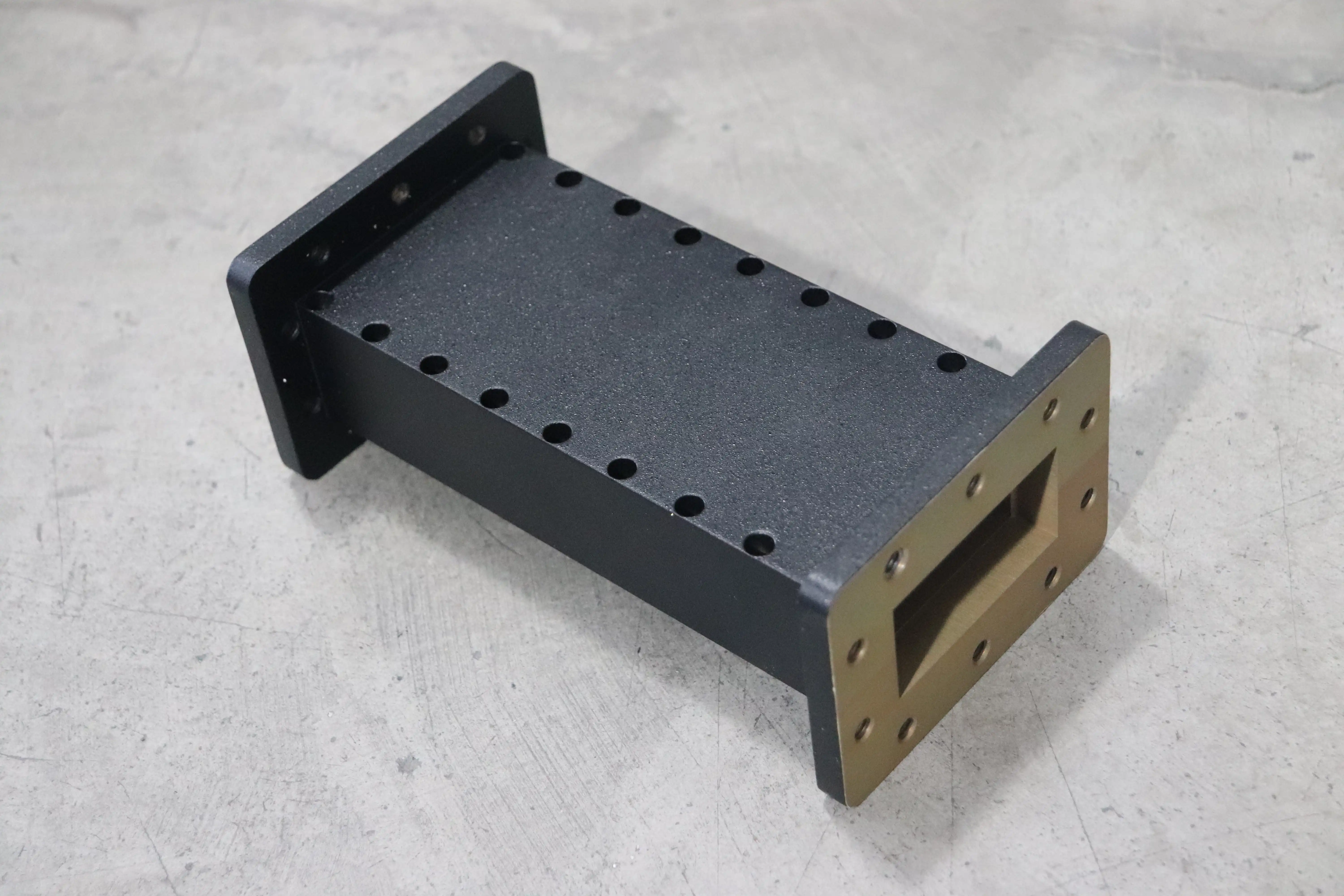
In the passband, stepped impedance filters usually have insertion losses of 0.2 to 0.5 dB, and at the second harmonic, they have stopband rejection of 40 to 50 dB. Because there are only so many impedance steps that can be used, the attenuation slope that can be made is limited. This means that the change from passband to stopband happens over a wider frequency range than with corrugated designs. Because field transitions are smoother and current crowding is less, corrugated filters have lower insertion loss—often below 0.15 dB. Their spread-out design lets them have sharper cutoffs and better stopband rejection, often reaching 60 dB within a smaller transition span. When it comes to applications like satellite earth stations, where every tenth of a decibel can affect link budget margins, corrugated designs are often the better choice, even though they cost more at first.
Physical Dimensions and Manufacturing Complexity
Because they only need a few sections to achieve mild rejection levels, stepped impedance filters usually take up less longitudinal room. This makes them ideal for setups that are limited in space on mobile or airborne platforms. Standard end mills and turning operations are used in the simple machining process, which means that prices are low and lead times are as short as four to six weeks for standard waveguide sizes. To make uniform, repeating groove patterns in corrugated filters, you need special tools. This makes manufacturing more difficult and can take eight weeks or more, depending on how customized the filters need to be. But there isn't much of a weight difference between the two types when they use the same base materials. For example, for waveguide shapes that are the same, the difference is usually less than 10%.
Power Handling and Thermal Stability
In high-energy settings, corrugated filters stand out because they can handle more power. The change in distributed impedance lowers electric field peaks that can cause multipactor discharge in vacuum systems or voltage breakdown in waveguides that are under pressure. As long as the heat is managed properly, corrugated designs can easily handle constant wave powers of more than 5 kilowatts and peak powers of more than 100 kilowatts. Stepped impedance filters can only handle continuous waves of about 2 to 3 kilowatts unless they are boosted with pressurization or bigger waveguide sizes. This is because they run into field concentration at sharp changes. You should also think about the thermal expansion factors. For both designs to work well, they need to use aluminum alloys with controlled thermal properties. This keeps the frequency stable even when the temperature changes a lot, like in spaceships or outdoor sites.
Cost Implications and Budget Planning
When the same base metals and plating options are used for both architectures, the cost of materials stays the same. The main difference in costs comes from the spending in production labor and tools. Stepped impedance filters have lower unit prices—usually 15 to 25% less expensive for normal setups. This makes them a good choice for projects on a budget or situations where moderate performance is enough. The higher price of corrugated filters is due to their better electrical performance and ability to handle power. They are a better deal in mission-critical systems where a component failure would cause big problems with operations. When defense contractors or satellite makers order a lot of filters, volume pricing structures become important. Making long-term agreements can cut the cost of filters by 10 to 15% while keeping the supply chain running smoothly.
Reliability and Maintenance Considerations
Both types of filters work as passive, non-tunable parts that don't need much upkeep once they're placed. Because corrugated waveguide low-pass filter designs don't have any sharp internal edges that could break when they're handled or exposed to vibration, they are a little more mechanically robust. If you specify them correctly, stepped impedance filters are still very reliable. The only ways they can fail are if the flange gets damaged or the metal wears away in corrosive conditions. For outdoor installations, hermetic sealing is very important. Helium leak testing and pressure decay monitoring make sure that moisture stays out for a long time, which keeps the VSWR performance high and stops corrosion. Environmental stress screening, such as thermal cycling and random vibration testing, should be required by procurement specifications to prove reliability in line with MIL-STD-810 or similar standards.
Selecting the Right Waveguide Low Pass Filter for Your Application
To choose the right waveguide low-pass filter, you must first carefully look at the system's needs, the environment in which it works, and the limits of its integration. Specifications for frequencies must include both passband limits with reasonable insertion loss and stopband needs measured by rejection levels at certain harmonic frequencies. There are a lot of physical limits on what can be designed, such as the amount of mounting space that is available, the suitability of the flange with current waveguide runs, and the weight limits for flying platforms.
Application-Specific Decision Criteria
When harmonic suppression needs to be higher than 55 dB to keep interference from receiving channels or nearby radar installations, corrugated filters are useful for radar transmitters that work in the X-band to Ku-band frequency range. Because it can handle more power, it can work with magnetron or klystron outputs without breaking down. Low insertion loss is important for satellite communication ground stations to get the most out of their link budgets. This is especially true for uplink paths, where every fraction of a decibel means more data flow or a longer operating range. When space is limited and low rejection levels are enough to meet regulatory requirements, stepped impedance designs may be used in telecommunications infrastructure that uses microwave backhaul links.
When research labs do precise measurements, they often need custom filter designs with passband flatness and phase linearity that can be tightly controlled. Advanced Microwave Technologies Co., Ltd. provides full design support, using our 24-meter anechoic room and testing tools that can handle frequencies up to 110 GHz to ensure that custom filters work well before they are made. Our ISO 9001:2015-certified methods make sure that the same thing happens in every production lot, which is very important when putting together multi-channel systems that need filters with the same properties.
Alternative Filter Technologies
Waveguide filters work best in high-power, low-loss situations, but other technologies should also be considered depending on the situation. Coaxial filters are small and work well for frequencies below 18 GHz, but they have more insertion loss and can't handle as much power as waveguide filters. Dielectric resonator filters are very selective and don't take up much space. They work well in receiver front-ends where strong signals from adjacent channels need to be thrown out. Cavity filters are flexible because they have tuning devices that let test tools or reconfigurable communication systems change the frequency. Microstrip planar filters make it possible to integrate them with printed circuit assemblies. This makes the assembly process simpler in commercial products that need to use moderate amounts of power and are cost-conscious.
Manufacturer Selection and Technical Resources
Working with skilled manufacturers gives you access to tried-and-true designs, quality certifications, and quick technical support all the way through the procurement process. Advanced Microwave Technologies Co., Ltd. has been making waveguide components, including waveguide low-pass filters, for over 20 years and works with defense contractors, satellite operators, and research institutions all over the world. Our range of products includes standard waveguide sizes from WR-650 to WR-28. We can also make them to order by offering different flange designs, special plating choices like gold for corrosion resistance, and pressurization connections for high-power installations. Full S-parameter files, mechanical CAD models that work with SolidWorks and AutoCAD, and thermal analysis reports make planning integration easier and speed up the testing process.
Conclusion
When deciding between stepped impedance and corrugated waveguide low-pass filters, you need to carefully weigh the performance needs against the available budget and time. Stepped designs are affordable and work well for many uses, while corrugated architectures are more expensive but deserve it because they are better at rejecting signals, handling power, and preventing insertion loss. To be successful at procurement, you need to have clear specifications, work with experienced manufacturers, and pay close attention to the little details of customization that make system integration work best. Advanced Microwave Technologies Co., Ltd. is ready to help you with your filter needs with their proven knowledge, wide range of testing options, and customer-focused service that guarantees mission success in radar, satellite, and telecommunications areas.
FAQ
1. What determines whether a stepped impedance or corrugated filter better suits my application?
The choice depends on three main things: the required stopband rejection depth, the ability to handle power, and the flexibility of the budget. Corrugated designs are usually needed for applications that need rejection of more than 55 dB at harmonic frequencies, like high-power radar transmitters or satellite uplinks that share spectrum with receive bands. In the same way, power levels above 3 kilowatts continuous wave favor corrugated designs because they have less field concentration. Stepped impedance filters are often chosen for projects that want to save money and accept mild rejection around 40 to 50 dB and lower power levels. They work reliably and don't cost as much.
2. How do I verify filter performance after installation?
Vector network analysis is used to measure S-parameters across the given frequency range for performance testing. Connect the filter between test ports that have been calibrated and sweep from below the passband to the stopband harmonics. During the passband, insertion loss should stay below certain limits, usually less than 0.3 dB for good designs. Return loss greater than 20 dB proves that the impedances are properly matched. Specification thresholds must be met for stopband rejection measured at second and third harmonic frequencies. For high-power testing, you need special tools and a controlled environment. Manufacturers usually give customers certified test data, so they don't have to check it themselves unless application-specific conditions call for it.
Partner with ADM for Superior Waveguide Low Pass Filter Solutions
Precision-engineered waveguide low pass filter solutions are made by Advanced Microwave Technologies Co., Ltd. They have ISO 9001:2015 certification and have been working with microwaves for over 20 years. Whether you need corrugated filters for high-power uses or stepped impedance designs for projects that need to be cost-effective, our expert team can help you with everything from the specification process to delivery. We work with defence companies, satellite operators, and telecommunications developers all over the world. We can customise our services to meet the exact needs of your system. We make sure that every waveguide low-pass filter manufacturer's product meets strict quality standards before it is shipped by using an advanced 24-meter measurement facility and testing tools that can handle frequencies up to 110 GHz. Get in touch with craig@admicrowave.com right away to talk about your filter needs, get complete datasheets and CAD models, or get a full quote. When you work with a reliable waveguide low-pass filter provider who is committed to the success of your goal, you can expect high reliability and performance.
References
1. Matthaei, G.L., Young, L., and Jones, E.M.T. Microwave Filters, Impedance-Matching Networks, and Coupling Structures. Artech House, 1980.
2. Levy, R. "Stepped Impedance Transformers and Filter Prototypes." IEEE Transactions on Microwave Theory and Techniques, vol. 14, no. 7, 1966, pp. 339-345.
3. Arndt, F., and Beyer, R. "Rigorous Analysis of Corrugated Waveguide Low-Pass Filters." IEE Proceedings - Microwaves, Antennas and Propagation, vol. 138, no. 2, 1991, pp. 97-102.
4. Collin, R.E. Foundations for Microwave Engineering. 2nd ed., IEEE Press, 2001.
5. Pozar, D.M. Microwave Engineering. 4th ed., John Wiley & Sons, 2012.
6. Marcuvitz, N. Waveguide Handbook. IEE Electromagnetic Waves Series 21, Peter Peregrinus Ltd., 1986.