Rigid vs Flexible Waveguide Assembly: Which One Should You Use
Your individual application needs will determine whether a rigid or bendable waveguide assembly is best for you. Rigid waveguides provide better electrical performance with low insertion loss. They work especially well in fixed sites that need to handle a lot of power, like radar systems and ground-based satellite stations. Flexible waveguides can be mechanically changed to fit different situations. This lets them route through tight areas and dampen vibrations in moving platforms like ships and airplanes. To get the most reliable system, you should choose a product that balances electrical performance measures like insertion loss, VSWR, and power capacity with installation limitations, environmental conditions, and long-term upkeep needs.
Understanding Rigid and Flexible Waveguide Assemblies
Waveguide assembly units work like special transmission lines, sending electromagnetic waves through hollow metal tubes instead of sending data along wires. The basic idea behind how it works is that waves are reflected within holes that are exactly sized. This allows for certain propagation modes, most often TE10, which change depending on the size of the waveguide and the frequency band.
What Defines a Rigid Waveguide?
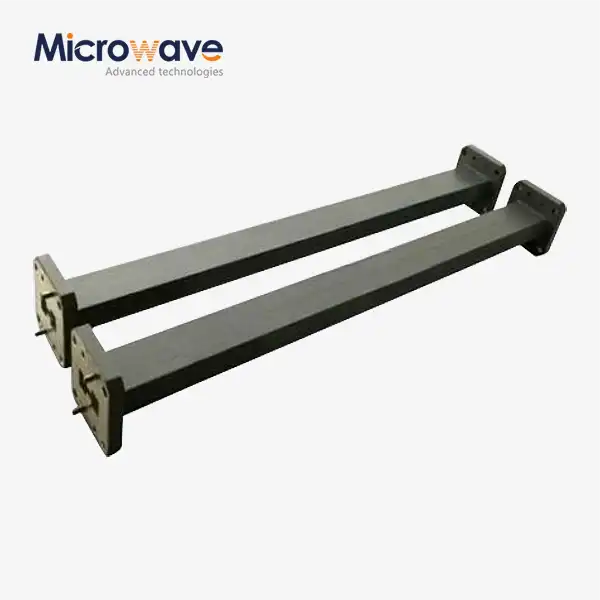
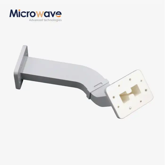
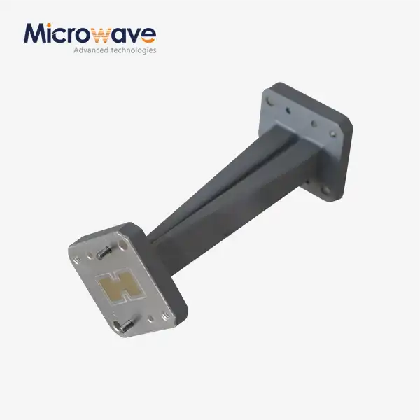
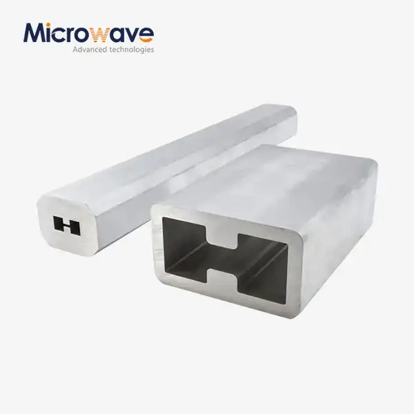
When you make a rigid waveguide out of aluminum, copper, or brass, you use sections that are straight or carefully formed and have exact interior measurements. Standard versions include the WR-90 for use in the X-band and the WR-284 for use in the lower S-band. When properly torqued, these systems have flanged connections that make sure there is perfect electrical continuity and stop RF leaks, such as those found in CPR, UG, or UBR standards. CNC cutting or extrusion is used to make the parts, and then they are plated on the inside (usually with silver) to reduce surface resistance and increase conductivity. To change directions or rotate polarization, rigid pieces can have mitered bends and twists that are all made to keep the internal cross-section the same.
Characteristics of Flexible Waveguides
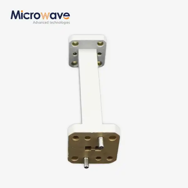
Flexible waveguides are made of silver-plated bronze or copper strips that are curved or overlapping and wound into a hollow structure that can bend. The complicated structure can bend in both the E-plane and the H-plane, and some types that can be twisted can also rotate axially. Protective coats made of rubber, silicone, or polished metal keep the inner core clean and flexible while keeping it safe from outside influences. These assemblies can handle misaligned parts, absorb thermal expansion, and keep out vibrations, all of which are very important in aircraft and mobile radar sites. On the other hand, they have a little more insertion loss than rigid ones—usually between 0.3 and 0.8 dB per meter, depending on the frequency, waveguide assembly, and bend radius.
Operating Frequency Ranges and Standards
Different frequency bands can be supported by fixed and flexible designs based on their cross-sectional sizes. The WR-90 works well from 8.2 to 12.4 GHz, and the WR-28 and other millimeter-wave sizes work well from 26.5 to 40 GHz. At ADM, our labs have testing tools that can go up to 110 GHz. This lets us check the performance across all radio frequencies, as well as the new 5G and 6G frequencies. Standards compliance, such as ISO 9001:2008 certification and RoHS conformance, makes sure that international purchasing rules and environmental laws that guide the defense and aircraft supply chains are met.

Core Comparison: Rigid vs Flexible Waveguide Assembly
When procurement teams know the differences in performance between rigid and flexible setups, they can match technology skills with application needs. The next section looks at some important factors that affect how reliable and cost-effective a waveguide assembly is.
Electrical Performance Metrics
It is better for rigid waveguides to have low insertion loss, usually between 0.02 and 0.1 dB per meter across their effective span. This low attenuation is due to smooth internal surfaces and a uniform shape that keep the best conditions for the main TE10 mode to propagate. Flexible structures lose more electricity—about 0.3 to 0.8 dB per meter—because the wavy surface makes more paths for current and small changes in resistance. Also, the VSWR requirements are different. Rigid parts usually get 1.05:1 or better, while flexible types usually get 1.20:1 to 1.30:1, based on the state of the bend. Power handling capacity strongly favors a rigid structure. At X-band frequencies, a WR-90 stiff waveguide can handle continuous wave power of more than 100 kW. Its limits are mostly set by the breakdown voltage at the flange, not by internal arcing. Flexible parts can only handle 10 to 30 kW of continuous power because their walls aren't very thick, and there could be hotspots at spiral peaks. This means that rigid parts are necessary for high-power radar transmitters and satellite transfer boosters because they can handle more power. Another important difference is phase stability. As long as proper thermal management is done, rigid parts keep the same electrical length no matter what the surroundings is like. If you move or change the temperature of flexible types, they might change phase by 2 to 5 degrees, which could affect phased array calibration and precision measurement tasks. At ADM, our testing procedures make sure that the phase stays stable under mechanical stress so that we can be sure of how it will work in changing settings.
Mechanical Durability and Environmental Resilience
Rigid waveguides work best in fixed systems that need to be resistant to vibration and maintain their shape over time. The solid design can handle shock loads, keep the flanges aligned during thermal cycles, and doesn't bend when outside forces act on it. Because of these features, rigid structures are perfect for infrastructure on the ground that is exposed to harsh weather and for use in industrial settings where machinery vibrates. For systems that need to allow for moving, flexible assemblies are important. Because the pieces fit together, vibrations that would normally stress hard connections are absorbed, protecting delicate flanges and mating surfaces. This feature is very important for gimbaled antenna systems that need flexible RF links because they are always rotating. The parts also fix any problems with thermal expansion that might exist between the equipment and the structure, which stops breakdowns caused by stress. To keep the curved core from permanently changing shape, the minimum bend radius requirements must be met. These are usually 2.5 to 4 times the waveguide width.
Installation Complexity and Spatial Requirements
Installation issues have a big effect on the total cost and time of the job. When rigid waveguides are put together, they need to be perfectly aligned, which can only be done by skilled workers using special tools. Straight runs may need special lengths to avoid having to be changed in the field, and changes in direction need bends that are made in the mill at a certain angle. This level of accuracy ensures the best performance, but it makes installation take longer and makes it harder to make changes in the field. Flexible parts make it easier to route through busy equipment bays and around obstacles because they don't need as many stiff sections and elbow fittings. Being able to make smooth shapes cuts down on connection points, which are a source of possible leakage or increased insertion loss. Installation teams like that they can save time and are less likely to damage the flanges while putting them together. Small mistakes in the sizes of the parts can be put together without having to be redone, which is helpful during the testing and integration of the waveguide assembly of prototypes.
Cost Considerations and Lead Times
When purchasing in large enough quantities, the cost of materials makes hard building the best choice. Standard catalog items ship fast from wholesalers, but special lengths and configurations take 4 to 8 weeks to make, based on how complicated they are. Economies of scale help large orders, especially for defense projects that need a lot of the same parts. Flexible parts cost more because they have to be made in a certain way, and the materials used to make the cores and protected jacketing are more expensive. Lead times are extended to 6 to 10 weeks for custom requirements such as specific flange types, jacket materials, and length standards. These lead times can be shortened with OEM partnerships like the ones ADM offers. These partnerships keep popular setups in stock and offer engineering help to improve designs before committing to production.
How to Choose the Right Waveguide Assembly for Your Application
To choose the right waveguide assembly, you need to carefully weigh the needs of your application against the waveguide's performance. The following framework helps people make choices about buying by taking technical and practical factors into account.
Defining Critical Application Parameters
Start by making a list of system needs that can't be changed. The size of the waveguide depends on the frequency band. For example, a Ka-band satellite terminal needs WR-28 or a similar millimeter-wave size, while an L-band radar needs WR-650 or bigger openings. Depending on the power level, hard structures may be needed, or flexible types may be better for managing heat. Figure out the total system insertion loss budget by deciding how much attenuation is okay for waveguide runs and active components. The environment affects the choice of materials and the level of protection needed. Jackets and base finishes that don't rust are needed for outdoor installs. Leak tests must be done on gas-tight parts in pressurized systems to make sure they are safe. Extreme temperatures can damage both electrical and mechanical components. Our ISO 14001:2015-certified methods make sure that environmental concerns are taken into account at every stage of production.
Balancing Performance Against Practical Constraints
Rigid waveguide infrastructure is helpful for high-power radar emitters that drive stable antenna arrays. The complicated construction is worth it because it ensures low insertion loss, high power handling, and long-term stability. When military surveillance systems are used in harsh environments, they depend on the mechanical strength of rigid parts to keep their balance even when they are vibrating and changing temperatures. When weight reduction and vibration isolation are more important than small changes in electrical performance, satellite packages and airborne systems prefer flexible parts. Being able to send signals through spacecraft structures that are limited in area or around airplane bulkheads gives designers a lot of freedom. For mechanically moving phased array antennas, the parts need to be able to bend so that the gimbal can move without putting stress on the stiff plumbing. Test and measurement uses present unique requirements. Flexible assemblies make links to laboratory vector network analyzers easier to use and protect the object being tested from stress caused by repeated connections. At ADM, our 24-meter microwave darkroom uses precise, flexible assemblies to allow antenna placement without adding measurement mistakes caused by rigid mechanical limits.
Leveraging OEM Expertise for Custom Solutions
When making difficult purchasing choices, it helps when manufacturers work together during the specification step. OEM providers like ADM offer engineering advice to help improve designs by offering different layouts that meet performance goals while cutting costs or lead times. When standard catalog items don't work, custom flange specs, non-standard lengths, and jacket materials made for a certain purpose can be added. With prototyping, you can test something before committing to making a lot of it. With quick-turn samples, you can test the electrical performance, mechanical fit, and fitting processes of a whole system. This step-by-step method lowers the risk in new designs and makes sure that the specs for purchases match the needs of operations. Our ISO 9001:2008 approval makes sure that the quality stays the same from the prototype to the finished product, keeping the performance traits that were proven in tests.
Installation, Maintenance, and Troubleshooting Best Practices
When you handle and maintain a waveguide assembly the right way, it will keep working well for a long time. The tips below come from decades of working in the field and helping mission-critical sites around the world.

Installation Procedures for Optimal Performance
For rigid waveguide installation, the flange waveguide assembly must be carefully lined up so that signals don't get reflected and there are no possible arcs at high power levels. Use accurate torque wrenches to load the bolts to the manufacturer's specifications. For standard WR-90 flanges, this is usually 40 to 60 inch-pounds. This will make sure that the gasket is compressed evenly and doesn't distort. Before putting the parts together, clean the matching surfaces with rubbing alcohol and lint-free cloths to get rid of any dirt or dust that could damage the electrical contact. When moving, flexible structures need to be made with minimum bend radius requirements in mind. Avoid quick changes that would put a lot of stress on the corrugated core and could cause it to bend permanently. Support the weight of the wire at regular intervals to keep it from sagging and putting too much twisting or pulling force on the flange connections. When specifying twistable parts, keep axial rotation within the ranges given, which are usually 90 to 180 degrees total. This will keep the jacket's integrity and keep the core from sticking. The entry of moisture is a major cause of failure. To get rid of dampness, pressurize waveguide systems with dry nitrogen or air to a positive gauge pressure, which is usually between 0.5 and 2 PSI. Set up tracking systems and pressure gauges to find leaks before moisture and fog hurt performance. As part of our production process, we test the seals under pressure to make sure they are solid before sending them out. During installation, field links need the same level of care.
Preventative Maintenance Strategies
Set up review times based on how vulnerable the area is to the environment and how important it is. For outdoor systems in naval or industrial settings, eye checks should be done every three months to look for corrosion, physical damage, or jacket wear. For climate-controlled indoor systems, the time between reviews may be extended to once a year. After installation, write down the standard VSWR and insertion loss readings so that you can compare them during regular testing to find degradation trends. Flange surfaces need to be re-torqued from time to time, especially in the first year after installation, when seals compress, and thermal cycles cause them to settle. During repair, write down the torque values to keep track of changes that could mean the seal is wearing out or the flange is damaged. Gaskets should be replaced as directed by the maker, which is usually every 5 years for indoor setups or every time the connection is taken apart for field-serviceable connections.
Troubleshooting Common Issues
More often than not, signal degradation shows up as higher insertion loss or VSWR jumps at certain frequencies. Isolate the damaged area in a planned way by taking sweep measurements and comparing the results to the initial data. When moisture gets in, broadband loss usually goes up, and VSWR changes with temperature. Check the pressure levels and look at the flanges for signs of condensation or rust. Damage to flexible assemblies shows up physically as kinked sections, jacket splits, or smoothed spots where the assembly was bent too much. These flaws cause breaks in the resistance, which cause echoes and could concentrate current flow, which causes the device to overheat. It's better to replace broken parts than to try to fix them in the field, because the level of accuracy needed to meet electrical standards is higher than what most sites can handle. Arcing at high power levels means that the joint is not aligned correctly, there is contamination, or the internal surfaces are breaking down. With our arcing detection waveguide technology and UV-clear fused silica viewports, systems can be monitored in real time to trip before they do any harm. In high-power radar and satellite uplink uses, where arc events can damage expensive parts, this safety is very helpful.
Conclusion
To choose between rigid and flexible waveguide assembly configurations, you need to carefully look at the working surroundings, electrical performance needs, and mechanical limitations. Rigid designs are great for fixed placements and high-power uses because they have better insertion loss, power handling, and long-term security. For mobile platforms, limited routing, and systems that can't handle vibrations, flexible assemblies are important for providing the necessary mechanical compliance. To be successful at procurement, you need to balance these technical factors against your budget, supply dates, and the supplier's skills. When you work with skilled OEM partners early on in the planning process, you can find ways to improve system performance while keeping costs low. Quality certifications, the ability to test, and quick technical help are what set suppliers apart who can support mission-critical apps throughout the lifetime of a product.
FAQ
What frequency ranges are best suited for rigid versus flexible waveguides?
Based on their cross-sectional sizes, both types can handle the same frequency bands. Rigid parts keep tighter limits that improve performance across the whole bandwidth, especially at higher frequencies above 40 GHz, where accuracy in dimensions is very important. Flexible systems work well within their designated bands, but their loss traits may be a little worse at the edges of the bands.
Can flexible waveguides handle high-power applications?
Power levels for flexible units are high—usually 10 to 30 kW, constant for standard sizes like WR-90—enough for many radar and communication systems. Rigid construction has better heat dissipation and voltage breakdown margins, which are useful for applications that need more power or constant operation close to maximum values.
What lead times should I expect for customized orders?
From wholesaler stock, standard setups ship in one to two weeks. Depending on the complexity of the design and the number of tests that need to be done, custom standards take 4 to 8 weeks for rigid parts and 6 to 10 weeks for flexible types. OEM providers like ADM can speed up important projects by working together on engineering and setting production priorities.
Partner with ADM for High-Performance Waveguide Solutions
Advanced Microwave Technologies Co., Ltd delivers waveguide assembly precision-engineered waveguide assemblysolutions backed by over 20 years of microwave expertise and ISO 9001 certification. Our comprehensive product range includes rigid and flexible configurations from 0.5 to 110 GHz, serving defense, aerospace, satellite communication, and industrial applications. As a trusted waveguide assembly manufacturer, we provide complete customization capabilities through our OEM services, supported by advanced testing in our 24-meter microwave darkroom. Our engineering team collaborates on feed network designs, X-band assemblies, and complex system integrations, ensuring your specifications are met with precision and reliability. Contact craig@admicrowave.com today to discuss your requirements and receive a detailed quotation. Let our technical expertise and responsive support empower your next RF system with proven performance.
References
1. Pozar, David M. Microwave Engineering, 4th Edition. John Wiley & Sons, 2011.
2. Collin, Robert E. Foundations for Microwave Engineering, 2nd Edition. IEEE Press, 2001.
3. Saad, Theodore S. Microwave Engineers' Handbook, Volume 1. Artech House, 1971.
4. Institute of Electrical and Electronics Engineers. IEEE Standard for Precision Coaxial Connectors (IEEE 287-2007).
5. International Organization for Standardization. ISO 9001:2015 Quality Management Systems – Requirements.
6. Military Standard. MIL-DTL-3922: Waveguide, Flexible, Radio Frequency. United States Department of Defense, 2018.