Planar Spiral Antenna Bandwidth, Gain, and Polarization Explained
Understanding the bandwidth, gain, and polarization characteristics of a Planar Spiral Antenna is vital when selecting RF components for mission-critical applications. These antennas leverage spiral geometry etched on flat substrates to deliver ultra-wideband performance and circular polarization stability across multi-octave frequency ranges. Advanced Microwave Technologies Co., Ltd. designs planar spiral antennas spanning 1 GHz to 40 GHz with low VSWR, compact form factors, and customizable specifications—making them indispensable for satellite communication, electronic warfare, and aerospace systems where frequency agility and reliable signal integrity define operational success.
Understanding Planar Spiral Antennas: Key Concepts and Working Principles
What Makes Spiral Geometry Effective for Wideband Performance
A Planar Spiral Antenna is made up of conductive arms etched onto a dielectric substrate in the shape of an Archimedean or equiangular spiral. The spiral works on the idea of frequency independence, which is different from resonant antennas that are tied to specific bands. The spiral is activated in different parts by different frequencies. Lower frequencies work on the outer turns, while higher frequencies are more concentrated near the center feed point. This traveling-wave behavior makes sure that the impedance and radiation patterns stay the same over very large frequency ranges. It is possible to get frequency ratios of 10:1 or even 30:1 without using tuning networks or multiple antenna arrays.
Bandwidth Characteristics and VSWR Control
With bandwidth, you can talk about the range of frequencies that the antenna works well on. Our Planar Spiral Antennas work across the whole 1 to 40 GHz spectrum with VSWR below 2:1, making them wideband. This low voltage standing wave ratio cuts down on signal reflections and insertion loss, making sure that power moves quickly from the transmitter to the antenna or from the antenna to the receiver. The flat impedance response, which is usually matched to 50 ohms by an integrated wideband balun, gets rid of the need for external matching parts and makes system integration easier, which is very important for buying teams that are looking at the total cost of ownership and the complexity of deployment.
Gain Definitions and Radiation Pattern Stability
When compared to an isotropic radiator, gain measures how well an antenna focuses energy in a certain direction. Gains from 3 dBi to 8 dBi are delivered by Planar Spiral Antennas, which cover the entire hemisphere with beamwidths between 70° and 90°. While high-gain directional antennas lose field of view, spiral antennas have a modest gain and a wide angular coverage, making them perfect for uses like radar warning systems and satellite telemetry that need to receive signals from multiple angles at the same time. The self-complementary geometry keeps the symmetry of the radiation pattern and the stability of the phase center even when the frequency changes. This lowers distortion in time-domain pulse applications like ground-penetrating radar.
Circular Polarization and Axial Ratio Performance
Polarization tells us how the electric field vector in the emitted wave is oriented. Planar Spiral Antennas naturally create circular polarization, which can be right-hand (RHCP) or left-hand (LHCP), based on the direction of the spiral wrapping. Circular polarization is much better than linear polarization because it lowers polarization mismatch losses when talking to platforms that are shaking or turning, stops multipath fading in cities, and counteracts Faraday rotation effects in ionospheric transmission. Our designs achieve axial ratios below 3 dB across most of the operating band. This guarantees good polarization purity, which is important for satellite ground stations and aircraft data links that need to work regardless of orientation.
When buying and engineering teams understand these basic ideas, they can compare antenna specifications to system needs. The way that bandwidth, gain, and polarization work together determines whether or not an antenna can work in a variety of situations without needing to be redesigned or multiple antennas to be installed.

Comparing Planar Spiral Antennas with Other Antenna Types: Informed Decision-Making
Planar Spiral vs. Patch Antennas
With their high directivity, patch antennas work great in narrowband applications, but they have trouble with bandwidth limits. Patch systems usually work over bandwidths of 5 to 10% around the center frequency, which means that antenna farms need to cover a lot of bands. Planar Spiral Antennas, on the other hand, offer multi-octave bandwidth in a single aperture, which makes the system simpler and lowers the cost of installation. Spirals are better for frequency-hopping communication systems and broadband signal intelligence platforms because they maintain gain and polarization purity across much wider spectrums, while patches achieve higher peak gains (8–12 dBi).
Planar Spiral vs. Log-Periodic Antennas
Scaled dipole groups in log-periodic antennas also make them work well in broad conditions. They are more directed than spirals, but they need bigger shapes and more complicated feed networks. Because Planar Spiral Antennas have a flat shape, they can be mounted on curved surfaces and fit into platforms with limited space, like UAVs and CubeSats. For polarization diversity, log-periodic designs usually give linear polarization, which needs to be mechanically rotated. This is not needed with Planar Spiral Antennas because they have circular polarization built in. This makes the mechanical design easier and improves stability in mobile applications where moving parts can cause failures.
Planar Spiral vs. Helical Antennas
Because they are three-dimensional, helical antennas take up a lot of room along their length, but they have great circular polarization and high gain in axial mode. This height limit makes things hard for flying platforms and marine installations that need to deal with profile drag and radar cross-section. Planar Spiral Antennas have the same level of polarization quality but a very low vertical profile—often less than 10 mm when the substrate and cavity backing are added. When put on the bodies of planes or missiles, the low-profile design lowers the aerodynamic cost and allows flush fitting, which keeps the performance traits of the platform.
Understanding these comparative trade-offs empowers procurement professionals to select antenna architectures aligned with specific performance priorities, spatial constraints, and operational environments. The choice between antenna types directly impacts system integration timelines, recurring costs, and long-term maintenance requirements.
Design and Simulation Insights for Optimal Planar Spiral Antenna Performance
Critical Design Parameters and Material Selection
Picking the right spiral geometry and substrate materials is the first step to getting the best performance from a Planar Spiral Antenna. The outer diameter determines the lowest frequency that can be used. At the cutoff frequency, the circumference usually needs to be close to one wavelength. The highest frequency limit is set by the inner feed point measurements and the design of the balun. For performance above 18 GHz, precise etching tolerances at the micron level are necessary. When choosing a substrate, it is important to keep the dielectric constant stability, loss tangent, and temperature expansion coefficients in mind. We use Rogers and Taconic laminates that meet IPC-6012 Class 3 standards. This makes sure that the electrical properties stay the same at temperatures ranging from -55°C to +85°C, which are common in defense and aerospace applications.
Simulation Tools for Performance Optimization
Modern electromagnetic simulation software lets you make a virtual prototype before making the real thing. Full-wave solvers are used to model how current flows, how radiation behaves, and how impedance changes with frequency. These tests show how changes in the design affect the axial ratio, gain flatness, and VSWR. This lets the design be improved over and over again until it meets strict requirements. Putting radar-absorbent material behind a cavity changes two-way radiation into one-way patterns that can be used for ground terminals. However, the phases must be carefully matched to avoid resonances that limit the bandwidth. Our 24-meter microwave darkroom can test from 0.5 GHz to 110 GHz, so we can compare simulation results to measurements to make sure that production designs meet theoretical expectations and client needs.
Quality Control and Performance Verification
Quality of manufacturing has a direct effect on how well electronics work. Automated optical inspection checks the widths and spacing of the spiral traces and finds problems with the way they were made before they are put together. Measurements with a vector network analyzer show that the VSWR is below the limits set by the manufacturer in all working bands. Axial ratio testing in quiet rooms with rotating sources proves the purity of circular polarization. Radiation pattern measurements check the beamwidth and gain flatness to make sure that parasitic resonances do not change the coverage that was intended. These steps of verification, which are done according to IEEE 149 standards and MIL-STD-810 environmental protocols, give procurement teams documentation that can be tracked back to support predictions of reliability and compliance with contractual requirements.
Advanced simulation capabilities and rigorous testing protocols distinguish high-quality suppliers from commodity vendors. Procurement teams benefit from partnering with manufacturers possessing in-house measurement facilities and electromagnetic modeling expertise, reducing technical risk and accelerating qualification timelines for new platform integrations.
Procurement Guide: Sourcing High-Quality Planar Spiral Antennas for Your Business
Evaluating Supplier Capabilities and Technical Support
To find trustworthy manufacturers of Planar Spiral Antennas, you need to look at more than just published datasheets. Check to see if your providers have ISO 9001, ISO 14001, or ISO 45001 certifications. These show that they follow standards for quality control, environmental responsibility, and safety at work. Check that your in-house test facilities have standardized equipment that can be tracked back to national standards. Suppliers that rely on third-party testing cause delays and problems with quality control. It is also important to have technical support—responsive engineering teams can help with integration problems, give S-parameter files for system simulations, and suggest design changes for certain operational scenarios. At Advanced Microwave Technologies, our team has more than 20 years of experience with radio frequency (RF) technology. We offer prototyping services and application advice throughout the whole buying process.
Interpreting Datasheet Specifications and Custom Options
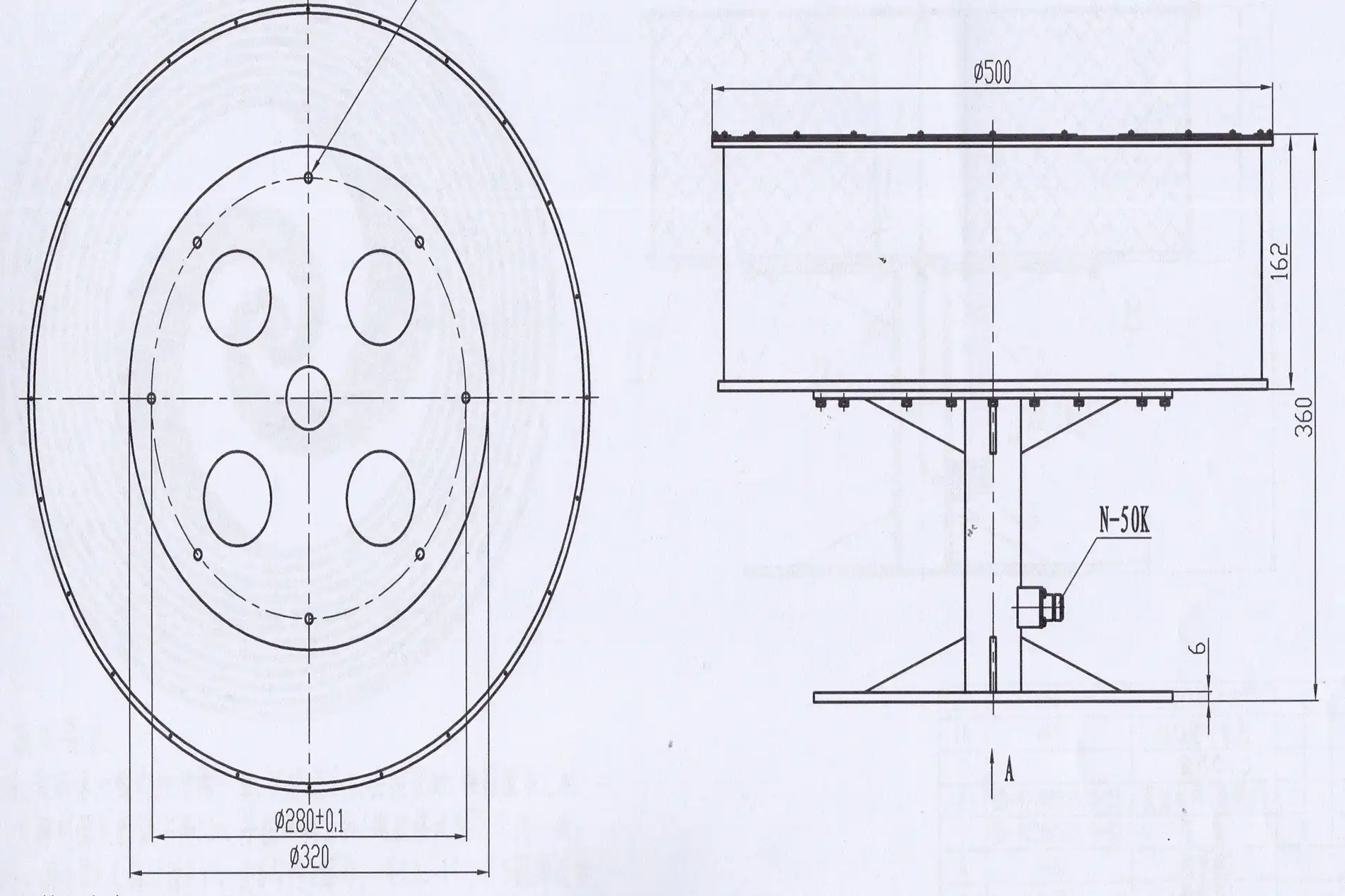
Important information in the datasheet includes the frequency range, VSWR limits, gain at certain frequencies, axial ratio across the band, and the ability to handle power. Watch out for specs that do not list test conditions. For example, gain values should list particular angles and frequencies, and VSWR must list how the measurements were made. Planar Spiral Antennas work best as receiving antennas or for sending small amounts of power. For sending large amounts of power, you need special designs for heat control and baluns. Customization choices are useful when normal goods cannot meet specific needs. For example, outer diameter scaling lets you change the frequency range; choosing the right substrate material for harsh locations is important, and special radomes are needed to protect the environment. Our OEM services offer custom solutions that include full integration support, quick prototyping, and management of the global supply chain.
Pricing Factors and Lead Time Considerations
Antenna prices depend on how complicated the design is, how much the substrate material costs, how precisely it is made, and how many are ordered. Because of their tight manufacturing standards and unique balun designs, multi-octave bandwidth antennas cost a lot. By making production more efficient, volume promises lower unit costs. Talk about expected quantities during the first talks. Customization levels affect lead times. Catalog items can be shipped within weeks, but fully customized designs need 8–12 weeks for engineering, prototyping, and setting up production. Critical path delays can be avoided by planning buying timelines around product development goals. A framework deals with qualified suppliers to make sure that you get enough capacity and good prices for projects that last more than one year.
Thorough supplier evaluation, specification interpretation, and strategic procurement planning minimize technical and business risks. Partnering with established manufacturers offering comprehensive support—from initial concept through production delivery—accelerates time-to-market and ensures antenna performance meets operational requirements.
Advantages and Applications: Why Choose Planar Spiral Antennas?
Key Advantages Driving Adoption
Planar Spiral Antennas have strong benefits that solve important problems in current radio frequency (RF) systems. The ultra-wideband feature gets rid of problems with spectrum fragmentation by combining multiple antenna arrays into a single coherent aperture. This is especially useful in electronic warfare systems that need to cover threat radars working across GHz to tens of GHz at the same time. Circular polarization naturally reduces orientation sensitivity, so the quality of the link stays the same even when satellite positions change or when planes do high-G maneuvers. Small form factors let them fit into platforms that are limited in size, like handheld tools and small satellites. Low-profile designs, on the other hand, lower aerodynamic drag and radar marks on combat aircraft. Manufacturing stability, with no moving parts or resonant cavities, ensures that the product will work reliably in high and low temperatures, as described in MIL-STD-810 testing procedures.
These advantages translate into tangible operational benefits: a simpler system lowers the costs of acquisition and maintenance; investments are safe against changing spectrum allocations because of frequency independence; and link availability is better in difficult propagation environments because of polarization diversity. The combination positions Planar Spiral Antennas as strategic components for organizations prioritizing operational flexibility and long-term value.
Mission-Critical Applications Across Industries
Planar Spiral Antennas are used in radar warning systems, electronic support measures, and satellite communication terminals in the defense and military industries. The hemispherical coverage pattern can find threats coming from many directions without having to mechanically scan, and the wideband response can pick up emissions from all over the electromagnetic spectrum. Ground-penetrating radar uses the antenna's ultra-wideband pulse accuracy to get clear pictures of what's below the ground for geological studies and checking out infrastructure. For better range and capacity, phone companies use spiral antennas in base stations that need to work on multiple bands and have different polarizations.
The CubeSat revolution in commercial space leverages flat spiral geometries meeting ISIPOD deployment standards, with circular polarization countering ionospheric effects during rapid orbital passes. Research institutions utilize customizable spiral designs for experimental communication systems, spectrum monitoring, and antenna measurement test ranges. This breadth of applications reflects the antenna's versatility and adaptability to diverse technical requirements across industries demanding uncompromising performance.
Conclusion
Planar Spiral Antennas are a high-tech answer for uses that need to work across a wide frequency range, keep the circular polarization fixed, and fit into a small space. When procurement workers understand the connections between bandwidth, gain, and polarization, they can make smart choices that meet technology needs and work within practical limits. When you compare antenna architectures, you can see how directivity, form factor, and frequency agility are affected by each other. This is important information for getting the best system performance for your money. Production antennas must meet strict requirements for mission-critical deployments. This is made possible by strict design processes and powerful simulation and measurement tools. Working with skilled makers that offer customization, technical support, and quality standards lowers the risk of buying things and speeds up the time it takes to put together next-generation communication and sensing systems.
FAQ
What frequency ranges do planar spiral antennas typically cover?
Planar Spiral Antennas have wide frequency ranges that depend on their outer diameter (low frequency) and the accuracy of their inner feed point (high frequency). In a single aperture, our designs cover frequencies from 1 GHz to 40 GHz. Depending on the needs of the application and the skills of the fabricator, we can also make versions that go as low as 500 MHz or as high as 110 GHz.
How does polarization mode affect wireless signal integrity?
Circular polarization keeps the signal strong no matter which way the transmitter and receiver are facing. This is very important for mobile platforms and satellite links. It counteracts ionospheric Faraday rotation and lowers multipath fading in urban environments. Linear polarization needs to be perfectly aligned, but it may get higher peak gains in fixed setups. Which one to use relies on how the links will be used and how much money is available for the links.
What customization options exist for industrial applications?
Customization options include changing the frequency range by scaling the shape, choosing the substrate material based on high or low loss needs, adding radomes for outdoor protection, and creating unique mounting interfaces. We work with clients to make sure that designs are the best they can be for each platform. This includes making sure that designs are mechanically compatible, block electromagnetic interference (EMI), and meet industry standards such as DO-160 for avionics and MIL-STD for defense systems.
Partner with ADM for Superior Planar Spiral Antenna Solutions
Advanced Microwave Technologies Co., Ltd. (ADM) stands ready to elevate your wireless infrastructure with precision-engineered Planar Spiral Antennas that offer high bandwidth, stable gain, and strong circular polarization. We use ISO 9001:2015-certified production methods and state-of-the-art testing facilities, such as our 24-meter microwave darkroom, to make sure that every antenna meets strict performance requirements from 1 GHz to 40 GHz. Our experienced engineering team offers full OEM services, from fast development to volume production, and full integration support, whether you need spiral antennas for satellite ground stations, electronic warfare systems, or telecommunications infrastructure. Get in touch with our experts at craig@admicrowave.com to talk about unique frequency bands, substrate materials, and mounting arrangements that meet your specific needs. ADM has been a trusted maker of Planar Spiral Antennas for over 20 years and has a lot of experience with microwaves. They offer the technical accuracy, quality certifications, and quick service that procurement professionals need.
References
1. Balanis, Constantine A. Antenna Theory: Analysis and Design, Fourth Edition. John Wiley & Sons, 2016.
2. Nakano, Hisamatsu, and Junji Yamauchi. Spiral and Helical Antennas: Frequency-Independent Antennas. Research Studies Press, 1987.
3. Corzine, Robert G., and Joseph A. Mosko. Four-Arm Spiral Antennas. Artech House Publishers, 1990.
4. IEEE Standard 149-1979. IEEE Standard Test Procedures for Antennas. Institute of Electrical and Electronics Engineers, 1979.
5. Volakis, John L., editor. Antenna Engineering Handbook, Fifth Edition. McGraw-Hill Education, 2019.
6. Kaiser, John A. The Archimedean Two-Wire Spiral Antenna. IEEE Transactions on Antennas and Propagation, Vol. AP-8, No. 3, May 1960.