AC Signal Amplifier Circuit Design for Better Signal Quality
An AC signal amplifier is a specialized electronic circuit designed to boost weak alternating current signals while preserving their original waveform characteristics. In mission-critical applications spanning satellite communications, defense radar systems, and aerospace navigation, these amplifiers ensure that signals maintain their integrity across transmission paths, reducing distortion and noise. By carefully balancing gain, bandwidth, and linearity, a well-designed amplifier circuit becomes the cornerstone of reliable RF and microwave communication systems that demand precision and stability.
Understanding AC Signal Amplifier Basics and Applications
Over the past 20 years, signal amplification technology has changed a lot. This is because people are always wanting higher bandwidth and better communication lines. Basically, signal amplification is the process of making an electrical signal louder without adding a lot of noise or distortion. This step is necessary in places where signals naturally get weaker over time because of things like distance, interference, or the limitations of the transmission medium.
Key Technical Specifications That Matter
When procurement engineers look at different amplification options, they need to pay attention to a number of performance measures that have a direct effect on how well the system works. Gain, which is given in decibels (dB), shows how much the amplifier boosts the sound. Industrial-grade amplifiers usually have gains between 20 dB and 60 dB, based on the needs of the application. Noise figure represents the additional noise from the amplification process itself, with a lower noise figure meaning better performance. At microwave frequencies, noise levels in good RF amplifiers are usually less than 2 dB.
The frequency response of an amplifier tells you what range of sounds it can handle well. Modern communication systems that use 4G LTE bands need amplifiers that cover 700 MHz to 2.7 GHz. New 5G networks will need amplifiers that cover millimetre waves above 24 GHz. Our testing capabilities at Advanced Microwave Technologies Co., Ltd. go up to 110 GHz, which lets us check how well amplifiers work with all current and future wireless technologies.
Distinguishing Analog and Digital Amplification
Analogue amplifiers directly process continuous signals, keeping the natural pattern properties that are needed for radar and satellite communication. When low latency and little signal processing delay are needed, these circuits work great. Digital amplifiers, on the other hand, turn signals into discrete values that can be processed. This makes them easier to program and more compatible with current software-defined radio systems.
Environmental factors are also very important when choosing an amplifier. Extreme temperatures, moisture, and physical stress make outdoor installations need ruggedised enclosures and better thermal management. Even though deployments inside are more controlled, they still need to take into account electromagnetic interference from nearby equipment and enough airflow to get rid of heat.
Core Components and Circuit Design Principles for Optimal Signal Quality
The building blocks of any good amplifier circuit are the basic electrical parts that are carefully chosen and put together. Each part of the overall performance envelope makes a unique contribution. Knowing these contributions helps procurement teams better judge the skills of suppliers.
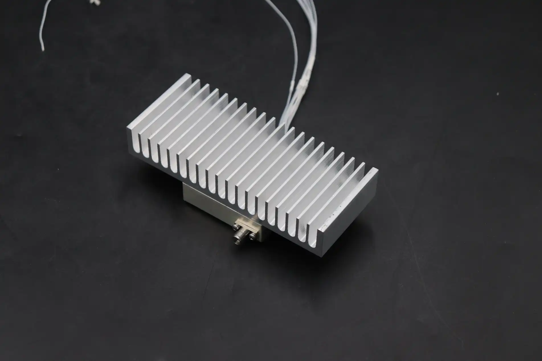
Essential Building Blocks of Amplifier Circuits
Transistors serve as the active amplifying elements, and bipolar junction transistors (BJTs) and field-effect transistors (FETs) each have their own benefits. High-electron-mobility transistors (HEMTs) are the best choice for microwave uses because they have better gain and less noise at frequencies above 10 GHz. Controlling large current flows through small input signals is how these semiconductor devices work. This effectively increases the power of the signal.
Capacitors play a number of important roles in AC signal amplifier circuits. Coupler capacitors stop DC voltages but let AC signals go between steps, making sure that transistor elements are properly biased. Bypass capacitors keep power supply voltages stable by sending high-frequency noise to ground. This stops oscillations that hurt signal quality. What kind of capacitor to use—ceramic, tantalum, or film—depends on the voltage values, frequency range, and need for temperature stability.
Resistors set bias points, gain levels, and feedback paths that keep the operation of an amplifier stable. Precision metal-film resistors with tolerances below 1% make sure that performance stays the same from one production run to the next. This is very important for OEM makers who are putting amps into bigger systems.
Advanced Design Strategies for Noise Minimization
To get great signal quality, you need to do more than just connect parts according to schematic diagrams. The layout of a circuit board has a big effect on how well it works, especially at microwave frequencies, where the lengths and shapes of the traces act as transmission lines with their own resistance properties. How impulses move through the circuit is affected by the design of the ground plane, where the vias are placed, and how far apart the components are.
Impedance matching makes sure that the most power can flow between circuit stages and connections to the outside world. Signal echoes, which show up as ripples in frequency response and lower overall gain, happen when impedances are not matched. To find these features, network analyzers use numbers called S-parameters. For example, S11 stands for input return loss and S21 for forward gain. When amplifiers are properly built, they keep S11 values below -15 dB throughout their working range.
Shielding techniques keep unwanted electromagnetic waves from reaching sensitive amplifier circuits and stop the amplifier itself from sending out these waves. When metal enclosures are properly grounded, they create Faraday cage effects that weaken fields that are trying to interfere. Internal compartmentalisation separates input and output steps even more, which stops feedback loops that make the system unstable.
Engineers have to make basic trade-offs when they try to balance gain, linearity, and bandwidth. It is more likely for higher gain stages to experience nonlinearity, which causes harmonic distortion and intermodulation products that mess up frequency channels next to them. To keep things stable, operations with a wider frequency often need less gain per stage. These engineering choices affect the final specs of the amplifier and show if it works with certain tasks.
Installation, Troubleshooting, and Maintenance Guide
Putting together signal-boosting gear the right way involves more than just mounting hardware and joining wires. Systematic startup processes reduce the chance of performance problems and set up a base for long-term, reliable operation.
Site Preparation and Compatibility Verification
Before the equipment comes, expert teams should make sure that the places where the equipment will be installed have the right weather controls. Temperature ranges must be within what the maker says they are, which for ruggedized equipment made for defense and aircraft uses is usually between -40°C and +70°C. Controlling humidity stops condensation, which eats away at connections and lowers the resistance of insulation.
Power supply infrastructure needs to be carefully looked at. For amplifiers, including an AC signal amplifier, to work, they need DC voltage sources that are stable, clean, and able to handle enough current. Even though switching power sources are small and efficient, they can add high-frequency noise that can damage RF systems. This risk is kept to a minimum by using linear regulators or switching sources that have output impedances below 0.1 ohms across the frequency range.
Wiring and Grounding Best Practices
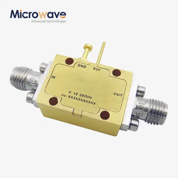
RF links need coaxial wires and connectors that are rated for the frequency range they will be used with. Because cable losses go up with frequency, microwave uses need short cable runs. SMA connectors work reliably up to 18 GHz, while 2.92mm and 2.4mm connectors can be used up to 40 GHz and 50 GHz, respectively.
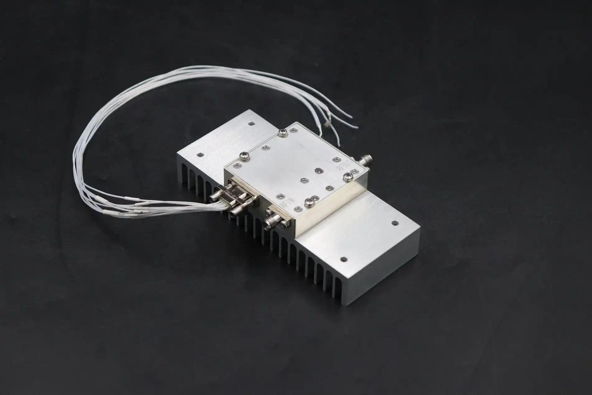
Grounding sets the reference potential for all signals and gives currents low-impedance ways to return. Low-frequency systems work well with single-point grounding, but high-frequency systems need multipoint grounding to keep ground loop areas to a minimum. Circuit boards should have dedicated ground planes that connect to chassis ground through several low-inductance routes.
Diagnostic Approaches for Common Issues
Most of the time, connection problems, wire damage, or bad termination cause signal loss. By measuring gain and return loss at each interface point, systematic testing with spectrum analyzers and network analyzers finds the exact location of the fault. While slow decline can be caused by aging or heat stress, sudden drops in gain usually mean that a component has failed or that there is a problem with the bias voltage.
On spectrum analyser screens, distortion shows up as harmonic content and intermodulation products. When input signal levels are too high, amplifiers go into compression, which means that output power doesn't rise linearly with input. Usually, a linear function is restored by lowering the input values by 3 to 5 dB. If distortion keeps happening even when the drive levels are right, it could mean that a component is worn out and needs to be replaced.
Visual checks for corrosion, loose connections, and signs of thermal stress, like discoloured parts, should be part of regular maintenance schedules. Using known reference signals for calibration checks makes sure that the amplifier gain stays within the limits. A lot of high-reliability apps need to be recalibrated every year or every other year, and they need to keep records that go back to national standards.
Comparing AC Signal Amplifiers with Other Signal Enhancement Solutions
Signal enhancement is a more general term that includes a number of different technologies, each of which is best for a different set of situations and system designs. When you understand these differences, you can make better procurement decisions that are in line with your actual operational needs.
Amplifiers Versus Repeaters and Boosters
In everyday speech, these terms are sometimes used interchangeably, but there are technical differences between them. The major job of amplifiers is to boost signals within a certain frequency range while keeping the quality of the signals. Repeaters get signals, boost them, and send them again. This increases the range, but it adds delay and the chance of instability if the send and receive signals couple up. Boosters are usually consumer-grade gadgets that are made to improve cell phone signals in homes or small businesses.
Professional amplifiers made for industrial use have exact gain controls, low noise levels, and stable operation even when power and temperature change. Due to these qualities, they can be easily integrated into complicated systems that need to work reliably. Even though consumer boosters are cheaper, they don't always come with the paperwork, licensing, and ability to be tracked that is needed for mission-critical deploys.
Analog Versus Digital Amplifier Architectures
Traditional analogue amplifiers, including an ac signal amplifier designed for specific signal conditioning tasks, work by processing signals in their native domain, which makes them simple, quick, and low-power. Because of these benefits, analog designs are better for real-time uses like radar processing and satellite ground stations, where signal delays build up over the course of the system.
Digital amplifiers use progress in digital signal processing and converting analogue signals to digital ones to use complex methods such as adaptive filtering and predistortion linearisation. Digital methods that let reconfiguration happen through firmware updates instead of hardware changes are good for software-defined radio systems. In exchange, more power is used, and processing takes longer, which might not be a problem in transmission base stations but is a problem in high-speed sensing uses.
Cost considerations go beyond the initial buy price and include things like how hard it is to install, how much power it uses, and how much it costs to maintain over its lifetime. For simple amplification tasks, analogue systems usually have lower total costs because they don't need as much supporting infrastructure. They don't need fast processors, memory, or complicated firmware. The extra cost of digital systems is worth it when their freedom and advanced features make them more useful in the workplace.
Conclusion
To create and use signal amplification solutions that work, you need to pay close attention to technical details, the quality of the parts, and the supplier's skills. Throughout this exploration of amplifier basics, circuit design, installation best practices, and buying strategies, the central theme remains: signal integrity is what makes system performance in mission-critical applications work.
Procurement professionals navigating this complex landscape benefit from partnering with well-known makers who have technical know-how, quality certifications, and full support capabilities. Choosing the right parts, installing them in the right way, and keeping up with their maintenance all work together to make sure that amplifier circuits work reliably for their whole life, supporting everything from next-generation 5G networks to advanced defense radar systems.
FAQ
1. Can a single amplifier support both WiFi and cellular signals simultaneously?
In theory, it is possible with designs that are wide enough, but in practice, it is usually better to have different boosters for WiFi signals (2.4 GHz and 5 GHz bands) and cellular signals (700 MHz to 2.7 GHz for LTE). Frequency-specific amplifiers improve noise performance and gain flatness within their target bands, giving better results than ultra-wideband limitations. In multi-band distributed antenna systems, each frequency band usually has its own amplifier chain, and signals are only combined at the antenna feed points.
2. What distinguishes indoor versus outdoor amplifier installation requirements?
For outdoor installations outside, you need weatherproof cases that meet IP65 or IP67 standards. These protect electronics from dust, rain, and changes in temperature. To stop damage from close hits, lightning protection and surge suppression become necessary. Indoor units don't need as much weather hardening, but they still need to be compatible with electromagnetic fields, have enough airflow, and work with the building's power systems. Thermal control methods are very different. For cold areas, outdoor units often have heating elements, while indoor setups use HVAC systems.
3. How do I determine whether analog or digital amplifiers better suit my industrial application?
When latency is important and real-time signal processing is needed without digital conversion delays, analog amplifiers are the best choice. Analogue architectures are often needed for radar systems, navigation equipment, and high-speed sensing platforms. Digital amplifiers are better when they need to be flexible, can be set up from a distance, or have advanced signal processing features that explain their extra complexity and power use. Digital methods work well with base station equipment and software-defined radio systems. This basic design choice is based on how much delay an application can handle, how much power it can use, and what features it needs.
Partner with Advanced Microwave Technologies for Superior RF Amplification Solutions
Advanced Microwave Technologies Co., Ltd. has been making precise RF and microwave parts for defence, aircraft, and satellite communication needs for more than 20 years. We know a lot about waveguide assemblies, coaxial components, and special amplifier solutions. These are all checked in our state-of-the-art 24m microwave darkroom, which can measure up to 110 GHz.
We know that projects need more than just catalogue items to be successful. They need quick technical help, the ability to make changes, and dependable delivery. Our ISO 9001:2015-certified manufacturing methods guarantee consistent quality, and our engineering team helps with all aspects of applications, from the initial design consultation to installation support and ongoing upkeep.
Our OEM services are flexible enough to handle projects of all sizes, from making a prototype for trying the idea to mass production for large-scale operations. You can meet tight project deadlines with the help of global logistics support, quick turnaround times, and competitive pricing structures for large orders.
Connect with our technical sales team at craig@admicrowave.com to talk about what you need from an AC signal amplifier. We'll help you understand the specifications, suggest the best solutions, and give you detailed quotes that meet your technical and financial goals.
References
1. Pozar, David M. Microwave Engineering, Fourth Edition. Wiley, 2011.
2. Gonzalez, Guillermo. Microwave Transistor Amplifiers: Analysis and Design, Second Edition. Prentice Hall, 1996.
3. Ludwig, Reinhold, and Gene Bogdan ov. RF Circuit Design: Theory and Applications, Second Edition. Pearson, 2008.
4. Razavi, Behzad. RF Microelectronics, Second Edition. Prentice Hall, 2011.
5. Cripps, Steve C. RF Power Amplifiers for Wireless Communications, Second Edition. Artech House, 2006.
6. Vendelin, George D., Anthony M. Pavio, and Ulrich L. Rohde. Microwave Circuit Design Using Linear and Nonlinear Techniques, Second Edition. Wiley-Interscience, 2005.