





low loss bandpass filters: Key Specs for Better RF Performance
Low-loss bandpass filters represent a cornerstone technology in modern RF and microwave systems, enabling precise frequency selection while preserving signal strength throughout transmission chains. These specialized components allow desired frequency bands to pass through with minimal insertion loss—typically under 1.0 dB—while effectively rejecting unwanted signals outside the passband. In mission-critical applications spanning satellite communications, defense radar systems, and aerospace navigation platforms, the difference between a standard filter and a low-loss variant can determine overall system viability. The growing complexity of wireless spectrum management, coupled with stringent power budget constraints in remote installations, has elevated low loss bandpass filters from convenient accessories to indispensable system elements that directly influence link reliability and operational range.
Understanding Low Loss Bandpass Filters: Fundamentals and Design
At the heart of any good RF system is the ability to separate certain frequency bands without affecting the purity of the data. Low-loss bandpass filters do this by carefully designing resonant structures that make the passband edges very sharp while keeping the insertion loss very low across the operating band.
Fundamental Operating Principles
The way these filters work is based on resonant cavity structures that hold electromagnetic energy at certain frequencies. These structures can be coaxial, waveguide, or a mix of the two. When signals with the design frequency go through the filter, they meet impedance-matched resonators that let them pass with almost no loss. Out-of-band signals, on the other hand, encounter high impedance gaps, which lead to rebound and attenuation. The sharpness of frequency selection and the possible insertion loss are both controlled by the quality factor (Q) of these resonators. Higher Q values mean better performance.
Core Design Parameters for Procurement Evaluation
Insertion Loss Characteristics: The passband insertion loss has a direct effect on receiver sensitivity and system gain limits. High-end coaxial designs lose only 0.3 to 0.8 dB because they use high-conductivity silver-plated brass housings. On the other hand, waveguide designs can lose less than 0.2 dB at microwave frequencies because they use air-dielectric propagation and have large surface areas that reduce resistive losses.
Return Loss and VSWR Performance: Enough return loss (usually >20 dB) keeps signal bounce to a minimum, which stops standing waves that mess up data being sent and make power transfer less efficient. Purchasing engineers should check the S11 parameter data across temperature ranges that are relevant to the deployment environment.
Bandwidth and Selectivity Balance: The filter's fractional bandwidth tells us how much energy it passes compared to the center frequency. Narrow bandwidths (1–5%) work well for blocking adjacent channels in crowded spectrum areas, while wider designs (10–20%) can handle modulated signals with large sidebands.
Power Handling Capacity: Filters that can handle steady RF power of 100W to several kilowatts are needed for high-power uses in radar transmitters and satellite ground stations. Corona discharge limits and the ability to remove heat become important factors for evaluation.
Material Considerations and Manufacturing Quality
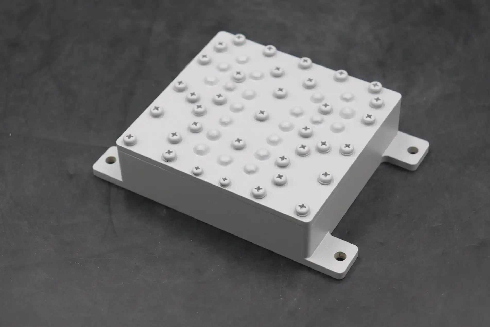
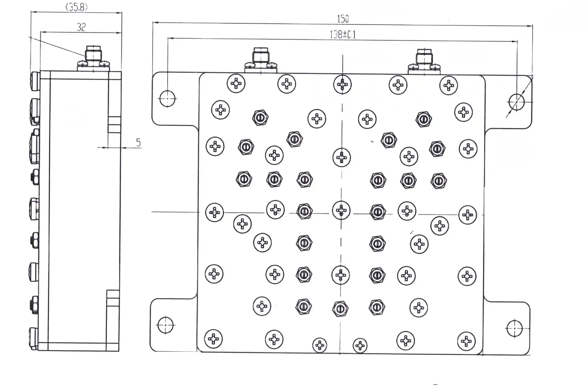
The actual structure has a big effect on how well the electricity works. Skin effect losses at microwave frequencies can be cut down by plating aluminum or brass bodies with silver that is at least 3–5 μm thick. Passive intermodulation (PIM) goods that mess up sensitive receiving bands can't happen with materials that aren't magnetic. Long-term performance stability under mechanical stress and thermal cycling depends on the torque specs for the screws and the quality of the connection contact. Precision manufacturing, which can be reached with CNC machining and tolerances below ±0.01mm, makes sure that the measurements of the resonator match electromagnetic models. This turns theoretical designs into reliable hardware.
Comparing Low Loss Bandpass Filters with Other Filter Types
By knowing the performance trade-offs between filter designs, you can make smart purchasing choices that meet the needs of your application and your budget.
Performance Differences Across Filter Topologies
Low Loss versus Standard Bandpass Filters: Regular bandpass filters that are good enough for consumer electronics may have insertion loss of 2 to 4 dB, which builds up as they are cascaded in complex RF chains. Low loss bandpass filters give up some of their small size and low cost to achieve performance of less than 1 dB. This keeps the signal strong in satellite links with limited power and increases the operating range of wireless backup systems.
Coaxial versus Waveguide Implementations: Below 10 GHz, coaxial bandpass filters work best because they have manageable size and Q-factors that reach 1,000 to 5,000. Above 10 GHz, waveguide filters are the best because their air-filled design gives them unbeatable Q-factors of over 10,000 and the ability to handle more power than coaxial structures can without breaking down.
Cavity Filters in Base Station Deployments: Cellular infrastructure relies on cavity filters a lot for duplexer tasks, where narrow guard bands split the send and receive bands and steep skirt selectivity is needed. These filters block 60–80 dB of offset frequencies while keeping insertion loss at about 0.5 dB. This keeps sensitive LNAs safe from transmitter noise.
Application-Specific Selection Criteria
Which type of filter to use depends on the frequency range, the exposure to the surroundings, and the limitations of the processing process. Aerospace uses waveguide screens because they can withstand vibrations and keep out outside air. Because they are small and work well, coaxial filters are chosen by telecommunications system designers for base station combiners. When research institutions make prototypes of trial systems, they often choose coaxial designs that can be changed and tuned over and over again while the systems are being developed.
Procurement Guide for Low Loss Bandpass Filters
To find mission-critical RF parts in the global supply world, you have to balance technical requirements with supplier skills, wait times, and the total cost of ownership.
Identifying Reputable Manufacturers and Suppliers
North American Providers: In the U.S., makers follow strict defense rules (ITAR, DFARS) and provide full traceability paperwork that is needed for aerospace projects. These suppliers usually keep their ISO 9001:2015 and AS9100 certifications up to date, which makes sure that quality management stays the same during all production cycles.
Asia-Pacific Manufacturing Ecosystems: Chinese suppliers like ADM offer reasonable prices and over 20 years of experience in microwave technology. Our ISO-certified factories and RoHS-compliant production methods make waveguide and low-loss bandpass filters that meet international quality standards and can be easily customized for OEM integration.
European Specialty Providers: European companies are great at making high-precision filters in small quantities for science instruments and specific defense uses. However, because of their smaller production sizes, they have longer wait times and higher prices.
Pricing Structures and Lead Time Expectations
Standard catalog filters ship in two to four weeks, but it takes eight to twelve weeks for custom designs that need electromagnetic simulation, prototyping, and tuning. Prices go up as the complexity goes up. Simple 3-pole coaxial filters cost a few hundred dollars, while high-power waveguide filters with strict requirements can cost several thousand dollars per unit. Long-term supply agreements and volume commitments give buyers the power to negotiate lower prices.
Best Practices for Supplier Assessment
Suppliers you can trust give full S-parameter data measured across certain temperature ranges, third-party test reports that back up claims about power handling, and documentation for environmental stress screening (MIL-STD-810 compliance for defense applications). Before agreeing to production amounts, ask for sample units to be tested in-house. You can find out how quickly the technical support team is by doing pre-sales engineering consultations. Suppliers who are willing to spend time getting to know your system design show that they are committed to a smooth integration.
Optimizing RF Performance with Low-Loss Bandpass Filters
Filter specifications can be turned into measurable system improvements in a wide range of deployment scenarios with the help of good integration practices and proactive performance management.
Common Integration Challenges and Solutions
Impedance mismatches at filter surfaces often cause signal reduction above a certain insertion loss. System VSWR performance is kept high by carefully choosing connectors and matching transmission line impedance, which can be done with precision coaxial adapters or waveguide transitions. Grounding techniques have a big effect on how well low loss bandpass filters reject signals. For example, proper chassis grounding stops RF from leaking through mounting structures, which would get around filter stopbands.
Installation and Matching Techniques
Putting filters close to sensitive receiver front-ends cuts down on cable losses that lower noise levels overall. Putting directional couplers after filters in high-power transmitters lets you keep an eye on the reflected power all the time. This lets you know right away if the filters are wearing out or if the antennas aren't matched up right. In precision uses, keeping the center frequency stable requires thermal management, such as passive heatsinking or active temperature control.
Real-World Performance Gains
In the southwestern United States, a satellite ground station operator added waveguide bandpass filters to their X-band uplink chain. This cut interference from nearby satellites by 25 dB while keeping insertion loss below 0.3 dB. This improvement made it possible for faster data rates and more stable links when the weather changed. Defense contractors that use airborne radar systems say that low PIM coaxial filters get rid of unwanted responses caused by nonlinearities in the components. This directly improves the ability to find targets in electromagnetic environments that are busy.
Future Trends and Innovations in Low Loss Bandpass Filters
As new wireless standards and demands for miniaturization continue to shape technological progress, filter design methods and manufacturing methods are also changing.
Material and Manufacturing Advances
With additive manufacturing, it is now possible to make resonators with complicated shapes that were not possible with traditional machining. This could lower production costs while keeping electromagnetic performance the same. Modern ceramics with dielectric factors that don't change with temperature allow for small filter designs that need to fit in small spaces. Using special plating methods to apply silver nanoparticle coatings makes the layers thinner, which increases conductivity while lowering material costs without sacrificing the performance of low-loss bandpass filters.
5G, IoT, and Next-Generation Wireless Systems
As 5G millimeter-wave bands (24–110 GHz) become more common, filter technologies that can handle bigger instantaneous bandwidths with flat group delay characteristics are needed to keep the purity of complex modulation. Massive MIMO antenna arrays need dozens of filter channels with precise amplitude and phase matching. This is a problem that has led to the creation of tunable filter architectures using MEMS or semiconductor varactor technologies. IoT sensor networks that have to work with very little power depend more and more on ultra-low-loss filters, which make batteries last longer by reducing RF chain losses.
Strategic Investment Considerations
Companies that want to invest in RF infrastructure for the long term should look at their suppliers' research skills and past performance in new frequency bands. Partners who are involved in standards-setting groups and who keep up-to-date measurement facilities, like our 24m microwave darkroom with 0.5-110 GHz test capabilities, are in a good position to meet changing technical needs. As spectrum allocations change, modular filter designs that allow for future frequency refarming through tuning changes offer upgrade options that are both cost-effective and flexible.
Conclusion
Low loss bandpass filters are still important technologies for high-performance RF systems that depend on signal integrity and spectral purity to work well. When procurement teams understand how design factors like insertion loss, selectivity, power handling, and weather resistance affect each other, they can choose parts that really meet the needs of the application instead of just checking off the right boxes on the datasheet. As technology continues to move toward higher frequencies, wider bandwidths, and more crowded spectrum environments, low-loss filter technology will continue to improve. New materials, more precise manufacturing, and better integration techniques will all lead to measurable performance gains. Companies that work with experienced suppliers that offer a wide range of technical services, thorough testing, and adaptable customization options can take advantage of these improvements while lowering the risk of technology becoming obsolete.
FAQ
How do low-loss bandpass filters improve RF signal quality in practical systems?
In more than one way, these low-loss bandpass filters improve the quality of the signal. They improve sensor signal-to-noise ratios by blocking out-of-band noise and interference. This lets weaker messages be picked up. With little insertion loss, transmitted power is kept, and communication range is increased without the need for new amplifiers. In crowded spectrum settings, sharp passband edges stop interference from neighboring channels, which lowers the number of bit errors in digital communications. The cumulative effect makes voice communications clearer, data throughput faster, and system operation more reliable when RF conditions are tough.
What factors impact cost and lead times for customized filter designs?
Cost and time are mostly affected by how complicated the design is. Standard resonator configurations that are made using tried-and-true methods ship quickly and at reasonable costs. Custom specs that need electromagnetic modeling, sample manufacturing, and tuning over and over again add 6 to 10 weeks to the development process. Costs go up a lot when you need unusual materials or parts that can work in harsh conditions (like those that are rated for space) or in conditions with high temperatures. The number of units ordered has a big effect on the price per unit, since the number of prototypes used incurs development costs that are spread out over production runs.
Are low-loss bandpass filters compatible with existing RF system architectures?
Standard connector interfaces (SMA, N-type, and waveguide flanges) make it easy for most filters to work with existing systems. Matching the impedance (usually 50Ω for coaxial and frequency-dependent for waveguide) makes sure that it works with regular transmission lines. Standard rack mounting or inline installation can be done with mechanical form factors. In retrofit situations, interface adapters or small changes to the wire assembly may be needed, but electrical compatibility is usually not a problem as long as the filters match the system's frequency bands and power levels.
Partner with ADM for Superior Low Loss Bandpass Filter Solutions
For more than 20 years, Advanced Microwave Technologies Co., Ltd. (ADM) has been creating and making precise RF and microwave parts for the toughest uses in the world. Our wide range of services, including modern antenna systems, waveguide kits, and coaxial filters, is backed by ISO 9001:2015 and RoHS approvals that guarantee quality and safety. We offer personalized technical talks to make sure that the parts you buy are exactly what your system needs, whether you're looking for low-loss bandpass filters for satellite ground stations, military radar systems, or next-generation wireless infrastructure. Before we ship any of our products, we make sure they work in our state-of-the-art 24m microwave lab, which can measure up to 110 GHz. As a reliable company that makes low loss bandpass filters for defense contractors, telecom installers, and research institutions around the world, we offer unique solutions with quick turnaround times and helpful customer service after the sale. Contact our team today at craig@admicrowave.com to discuss your specific RF filtering challenges and discover how our proven track record can enhance your system performance and reliability.
References
1. Pozar, David M. Microwave Engineering, 4th Edition. Wiley, 2012. Print.
2. Hunter, Ian C. Theory and Design of Microwave Filters. Institution of Engineering and Technology, 2001. Print.
3. Matthaei, George L., Leo Young, and E.M.T. Jones. Microwave Filters, Impedance-Matching Networks, and Coupling Structures. Artech House, 1980. Print.
4. Hong, Jia-Sheng, and M. J. Lancaster. Microstrip Filters for RF/Microwave Applications. Wiley-Interscience, 2001. Print.
5. Cameron, Richard J., Chandra M. Kudsia, and Raafat R. Mansour. Microwave Filters for Communication Systems: Fundamentals, Design, and Applications. Wiley, 2018. Print.
6. Levy, Ralph. "Filters for Communications Satellites." IEEE Transactions on Microwave Theory and Techniques, vol. 32, no. 9, 1984, pp. 1042-1054. Print.
YOU MAY LIKE
 VIEW MORESlotted Waveguide Array Antenna
 VIEW MOREIndustrial Microwave Sliding Short
 VIEW MOREcpw waveguide
 VIEW MOREWaveguide Single Channel Rotary Joint
 VIEW MOREDouble-Ridged Waveguide Loop Coupler
 VIEW MORELow Phase Noise Amplifier
 VIEW MOREConical Dual circular Polarization Horn Antenna
 VIEW MORECassegrain Antenna
