Installation Guide and Best Practices for Parabolic Antennas
Installing a parabolic antenna requires precision and careful planning to ensure optimal performance and longevity. This comprehensive guide outlines the essential steps and best practices for installing parabolic antennas across various applications. From site selection and preparation to alignment techniques and maintenance protocols, we cover all aspects of parabolic antenna installation to help you achieve maximum signal strength and reliability. Whether you're setting up a satellite communication system, radar installation, or telecommunications infrastructure, these expert guidelines will help you optimize your parabolic antenna performance.
Site Selection and Preparation
Evaluating Environmental Conditions
Choosing the right location for your parabolic antenna is crucial for its performance and longevity. When evaluating potential installation sites, consider factors such as wind load, precipitation patterns, and temperature variations. Parabolic antennas with larger aperture diameters (ranging from 30 cm to 12 m) are particularly susceptible to wind forces, which can affect alignment precision and structural integrity. Advanced Microwave Technologies' parabolic antennas are designed with durable materials like aluminum, steel, or composite reflectors that can withstand harsh environmental conditions, but proper site selection remains essential. For coastal or high-humidity environments, aluminum reflectors with corrosion-resistant coatings are recommended to prevent degradation over time. Additionally, ensure the site has minimal obstructions in the signal path, as parabolic antennas require clear line-of-sight to operate effectively across their frequency range of 1 GHz to 110 GHz. Conduct a thorough site survey to identify potential obstacles such as buildings, trees, or terrain features that could introduce signal interference or physical restrictions for installation and maintenance activities.
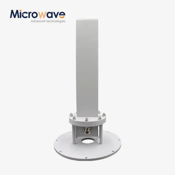
Foundation and Mounting Structure Requirements
The foundation and mounting structure for a parabolic antenna must be engineered to support both the static load of the antenna system and dynamic forces from environmental factors. For ground-based installations, concrete foundations with appropriate reinforcement are typically required, with specifications varying based on the antenna size and local building codes. The mounting structure should be designed to minimize vibration and movement, as even minor misalignments can significantly impact the performance of high-gain parabolic antennas (capable of up to 60 dBi). Advanced Microwave Technologies offers both fixed and adjustable mounting options to accommodate various installation scenarios and alignment requirements. For rooftop installations, additional structural reinforcement may be necessary to support the antenna load and ensure building safety. The mounting structure should also include provisions for cable management to protect feed lines from environmental damage and prevent unnecessary strain on connectors. When installing multiple parabolic antennas, proper spacing must be maintained to prevent signal interference and ensure each unit has adequate clearance for alignment adjustments and maintenance access.
Access and Safety Considerations
Installation of parabolic antennas often requires working at heights and with heavy equipment, making safety planning essential. Ensure all installation personnel have proper training and safety equipment, including fall protection systems when working at elevation. Plan the installation process to include safe access routes for both equipment and personnel, considering the potential need for future maintenance activities. For larger parabolic antennas, crane access and staging areas must be identified in advance. Additionally, be aware of potential RF exposure risks, particularly with high-power transmission systems, and implement appropriate safety measures and signage. Advanced Microwave Technologies provides comprehensive installation documentation that includes safety guidelines specific to each antenna model. When installing in public or shared spaces, consider security measures to prevent unauthorized access or tampering. The installation area should also be designed to accommodate diagnostic equipment that may be needed during commissioning or troubleshooting. Creating a detailed installation plan that addresses these safety considerations not only protects personnel but also helps ensure the parabolic antenna is installed correctly and efficiently, minimizing downtime and reducing the risk of equipment damage during the installation process.

Assembly and Installation Techniques
Unpacking and Component Verification
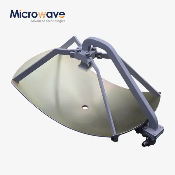
The installation process begins with careful unpacking and inspection of all parabolic antenna components. Advanced Microwave Technologies provides precisely manufactured parabolic reflector antennas of both primary focus feed type and back-fed type, each requiring specific handling procedures. Upon receiving the shipment, verify that all parts are present according to the packing list, including the reflector, feed assembly, mounting hardware, and any additional accessories. Inspect each component for shipping damage, particularly checking the parabolic reflector surface for dents or deformations that could affect performance. Even minor damage to the reflector can significantly impact the antenna's gain and directivity, especially in high-frequency applications up to 110 GHz. Document any issues immediately with photographs and contact Advanced Microwave Technologies' technical support team if replacement parts are needed. For larger parabolic antennas with diameters exceeding 2 meters, specialized lifting equipment may be required for safe handling. Follow the manufacturer's unpacking sequence to prevent stress on critical components. Before proceeding with assembly, verify that all mounting hardware matches the specification for your installation environment, ensuring compatibility with the mounting structure and sufficient strength to withstand expected wind loads and other environmental forces.
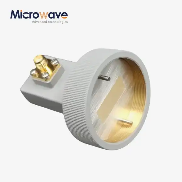
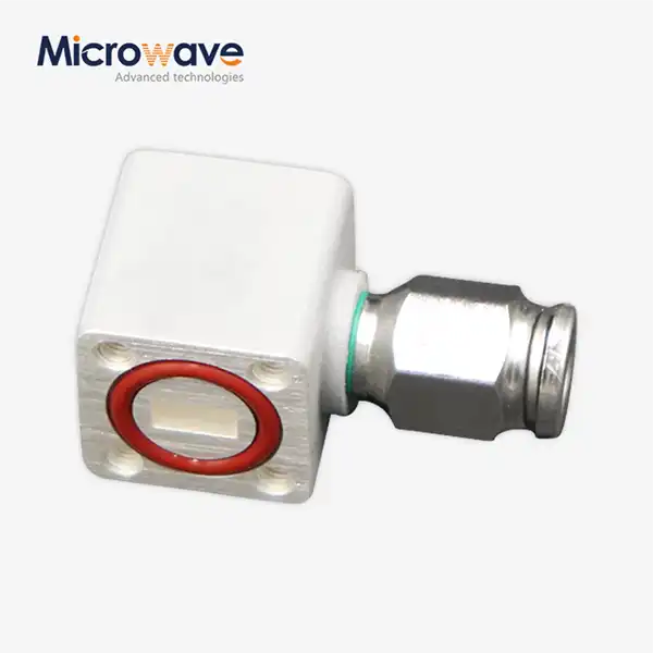
Reflector Assembly and Feed System Installation
Assembling the parabolic antenna requires precision to maintain the geometric accuracy essential for optimal performance. Begin by assembling the reflector according to the manufacturer's instructions, paying careful attention to maintaining the parabolic curve that gives these antennas their distinctive properties. For segmented reflectors, ensure all sections align perfectly to form a continuous parabolic surface. Next, install the feed system, which varies depending on whether the antenna is a primary focus feed type or back-fed type. The feed system must be positioned precisely at the focal point of the parabola to achieve maximum gain (up to 60 dBi depending on the model). Advanced Microwave's parabolic antennas feature precision-engineered feed systems optimized for specific frequency ranges, but they require careful installation to maintain performance specifications. When installing the feed system, verify the polarization orientation (linear or circular) matches the system requirements for your application. Secure all waveguide connections with the specified torque values to prevent signal leakage while avoiding damage to components. For weatherproofing, apply appropriate sealants to all connections, ensuring the integrity of the 50 Ohm impedance system throughout the installation. Prior to mounting the fully assembled antenna, perform a final inspection to verify all components are properly secured and aligned according to the assembly drawings.
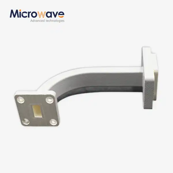
Cable Management and Weatherproofing
Proper cable management and weatherproofing are essential for ensuring the long-term reliability of parabolic antenna installations. Begin by planning the cable routing path from the antenna to the associated equipment, minimizing bend radius stress and physical exposure to environmental hazards. For waveguide installations, use proper support brackets at recommended intervals to prevent sagging or twisting that could degrade signal quality. When installing coaxial cables, maintain the manufacturer's specified minimum bend radius to prevent impedance mismatches and signal degradation. All outdoor connections should be thoroughly weatherproofed using industry-approved methods, including weatherproofing tape, heat-shrink tubing, or specialized weatherproofing kits. Advanced Microwave Technologies recommends double-layer weatherproofing for critical connections in harsh environments. Install drip loops in cable runs to prevent water ingress into equipment connections, and secure cables with UV-resistant ties at appropriate intervals. Ground the system according to local electrical codes and industry best practices, installing lightning arrestors where required to protect sensitive equipment. For installations in extreme environments, consider additional protective measures such as cable trays or conduits. Document the complete cable installation with photographs and detailed drawings to facilitate future maintenance and troubleshooting. Well-executed cable management and weatherproofing not only protect the physical components but also ensure the parabolic antenna maintains its specified electrical performance characteristics across the operating frequency range of 1 GHz to 110 GHz.

Alignment and Optimization
Azimuth and Elevation Adjustment Procedures
Precise alignment is critical for maximizing the performance of parabolic antennas, particularly in applications requiring high gain and narrow beamwidth. Advanced Microwave Technologies' parabolic antennas are engineered for exceptional directionality, but this characteristic also makes them sensitive to alignment errors. Begin the alignment process by establishing accurate reference points using GPS coordinates or surveying equipment to determine the exact azimuth (horizontal) and elevation (vertical) angles required for your specific application. For satellite communications, these coordinates will depend on the orbital position of the target satellite and your geographic location. The adjustment procedure should follow a systematic approach, starting with a coarse alignment using visual sighting tools or laser pointers, followed by fine-tuning based on signal strength measurements. Advanced Microwave's adjustable mounting systems provide precise control for these adjustments, with some models offering micrometer-level precision for critical applications. When adjusting both azimuth and elevation, it's important to secure one axis while adjusting the other to prevent unintended movement. For larger parabolic antennas, the adjustment process may require multiple technicians working in coordination. Throughout the alignment process, use appropriate signal strength measurement equipment calibrated for your specific frequency range (1 GHz to 110 GHz) to verify the effectiveness of each adjustment. Document the final alignment settings, including any reference marks or indicators that can be used for future verification.
Signal Strength Testing and Measurement
After completing the physical alignment of the parabolic antenna, comprehensive signal testing is essential to verify performance and optimize system parameters. Begin by connecting appropriate test equipment suitable for your frequency range, such as spectrum analyzers, network analyzers, or specialized satellite finders for satellite communications applications. Advanced Microwave Technologies provides guidance on recommended test equipment specifications for their various antenna models. Perform baseline measurements of signal strength, signal-to-noise ratio, and other relevant parameters based on your specific application requirements. For bidirectional communication systems, test both transmission and reception capabilities across the operational frequency range. Pay particular attention to signal quality at the band edges, as this can indicate potential alignment or polarization issues. For dual-polarized systems, verify isolation between polarization planes to ensure they meet specification requirements. The parabolic antenna's narrow beamwidth characteristic should be evident in the measurements, with signal strength dropping significantly with even small angular deviations from the optimal alignment. Create a comprehensive test report documenting all measurements under various conditions, including different weather scenarios if possible. Advanced Microwave's parabolic antennas are designed to maintain stable performance across operating conditions, but environmental factors can influence signal propagation. For critical installations, consider implementing a continuous monitoring system to track performance over time and identify any degradation that might require maintenance or realignment.
Polarization Optimization Techniques
Polarization alignment is a critical yet often overlooked aspect of parabolic antenna installation that can significantly impact system performance. Advanced Microwave Technologies' parabolic antennas support both linear and circular polarization options, each requiring specific optimization techniques. For linearly polarized systems, ensure that the polarization orientation of the antenna precisely matches that of the transmitting or receiving station. Even small rotational misalignments can cause substantial signal loss, particularly in cross-polarized interference scenarios. Use a polarization alignment tool or spectrum analyzer with polarization measurement capabilities to verify and optimize the orientation. For circularly polarized systems, verify the correct sense (right-hand or left-hand) for your application and ensure that the feed system is properly configured. In more complex deployments involving frequency reuse through orthogonal polarization, precise adjustment becomes even more critical. Advanced Microwave's high-performance parabolic antennas can achieve excellent cross-polarization isolation when properly optimized, enhancing system capacity and reducing interference. For systems operating in environments with significant atmospheric effects, consider how polarization may be affected by rain, ice, or other conditions, and implement appropriate compensation strategies. Document the final polarization settings, including rotational reference points that can be used for verification during future maintenance. For installations requiring remote adjustment capabilities, consider implementing motorized polarization control systems that can be fine-tuned in response to changing conditions or requirements. Proper polarization optimization ensures that the parabolic antenna delivers its full performance potential across its operating frequency range from 1 GHz to 110 GHz.
Conclusion
Installing parabolic antennas requires careful attention to detail, from site selection and preparation to final alignment and testing. Advanced Microwave Technologies' comprehensive range of parabolic antennas provides exceptional performance across diverse applications, but proper installation is key to achieving optimal results. By following these guidelines, you can ensure reliable operation and maximum signal quality from your parabolic antenna system.
Looking for expert support with your parabolic antenna installation? Advanced Microwave Technologies Co., Ltd offers comprehensive technical assistance backed by over 20 years of industry experience. Our ISO:9001:2008 certified and RoHS compliant products come with full installation support and customization options to meet your specific requirements. Contact our team today at sales@admicrowave.com to discuss your parabolic antenna needs and discover how our expertise can enhance your communication systems.
References
1. Johnson, R.C. and Jasik, H. (2023). Antenna Engineering Handbook, 5th Edition. McGraw-Hill Professional.
2. Balanis, C.A. (2022). Antenna Theory: Analysis and Design, 5th Edition. Wiley.
3. Milligan, T.A. (2021). Modern Antenna Design, 3rd Edition. IEEE Press.
4. Huang, Y. and Boyle, K. (2023). Antennas: From Theory to Practice, 2nd Edition. Wiley.
5. Volakis, J.L. (2022). Antenna Engineering: Principles and Practice. Cambridge University Press.
6. Stutzman, W.L. and Thiele, G.A. (2023). Antenna Theory and Design, 4th Edition. John Wiley & Sons.