Installation and Maintenance Guide for Feed Fired Lens Antenna
The Feed Fired Lens Antenna represents a pinnacle achievement in microwave engineering, combining sophisticated electromagnetic principles with practical design considerations to deliver exceptional performance across various applications. This comprehensive guide provides detailed instructions for proper installation and maintenance of Feed Fired Lens Antenna systems, ensuring optimal functionality and extended operational lifespan. By adhering to these guidelines, users can maximize the efficiency and reliability of their antenna systems while minimizing potential issues that might compromise performance. Advanced Microwave Technologies Co., Ltd. brings over two decades of expertise in microwave product engineering to help users navigate the complexities of these sophisticated systems.
Pre-Installation Planning and Site Preparation
Environmental Considerations for Feed Fired Lens Antenna Placement
The location where you install your Feed Fired Lens Antenna significantly impacts its performance and longevity. Feed Fired Lens Antennas operate within specific environmental parameters that must be carefully assessed before installation. First, evaluate the surrounding area for potential signal obstructions such as buildings, trees, or other structures that could interfere with the antenna's line-of-sight requirements. The antenna should be positioned with a clear view of the target satellite or communication source. Additionally, consider weather patterns in your region—strong winds, heavy precipitation, and extreme temperatures can all affect performance. Advanced Microwave's Feed Fired Lens Antennas are designed with durable materials including high-grade aluminum and copper components that withstand environmental challenges, but proper placement remains crucial. For optimal performance, the installation site should also account for accessibility for maintenance, protection from physical damage, and minimal exposure to corrosive elements like salt spray in coastal regions. Conducting a thorough site survey with appropriate tools to measure signal strength across different potential locations can help identify the optimal placement position.
Foundation and Mounting Structure Requirements
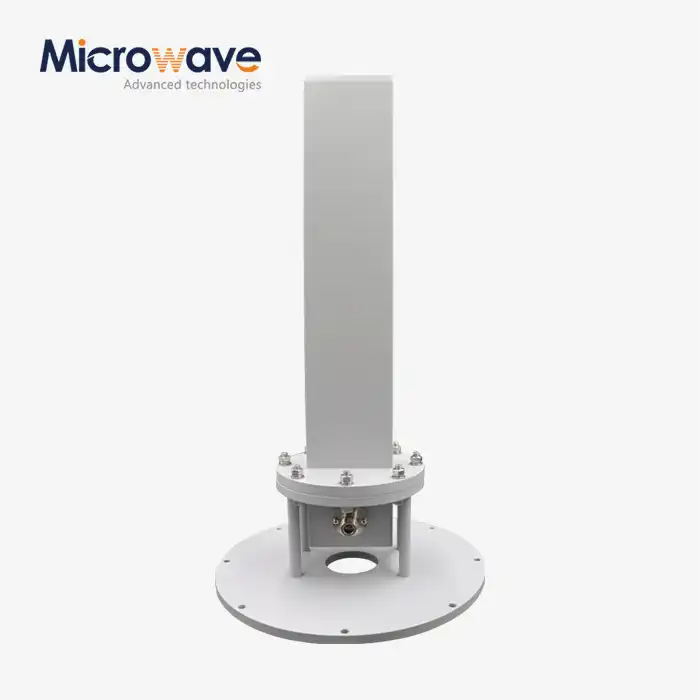
A stable foundation is essential for the proper functioning of Feed Fired Lens Antenna systems. These antennas, which operate across a frequency range of 1 GHz to 40 GHz, require precision alignment that can only be maintained with a secure mounting structure. Begin by assessing the weight and wind load specifications of your specific Feed Fired Lens Antenna model. Typically, these antennas require reinforced concrete foundations when installed at ground level, with specific depth and composition requirements based on local soil conditions and building codes. For roof-mounted installations, structural engineering analysis is necessary to ensure the building can support both the static weight and dynamic forces during adverse weather conditions. The mounting structure itself should be constructed from corrosion-resistant materials compatible with the antenna's materials to prevent galvanic corrosion. Advanced Microwave Technologies offers custom mounting solutions specifically designed for their Feed Fired Lens Antenna models, ensuring compatibility and optimal performance. These mounts incorporate vibration damping features to maintain the precision alignment necessary for the antenna's high gain specifications (30 dBi to 45 dBi). The foundation and mounting structure must also account for thermal expansion and contraction cycles, particularly in regions with significant temperature variations, as these can affect the critical alignment parameters of the feed system relative to the lens.
Tools and Equipment Checklist for Installation
Proper preparation before installation of a Feed Fired Lens Antenna saves time and prevents potential damage to the sophisticated components. Assemble the following essential tools: calibrated torque wrenches to ensure proper tightening of mounting hardware without overtightening; precision levels and digital inclinometers for accurate alignment; signal strength meters appropriate for your frequency range to verify signal quality during installation; weather-resistant electrical tape and appropriate connectors for cable terminations; and personal protective equipment including gloves, safety glasses, and fall protection equipment for elevated installations. Specialized tools may include waveguide flange alignment pins, connector wrenches specific to your connector type (whether flanged or coaxial as offered by Advanced Microwave Technologies), and RF power meters for system verification. Additionally, prepare documentation including installation manuals, site surveys, frequency coordination information, and regulatory compliance documents. For the Feed Fired Lens Antenna specifically, include tools for precise feed alignment relative to the lens, as this critical relationship determines the amplitude and phase distribution across the aperture field. Advanced Microwave Technologies provides detailed specifications with each antenna, including recommended torque values for different fastener sizes and materials. Having spare parts such as fasteners, gaskets, and connector components on hand can prevent installation delays if items are damaged during the process. Finally, ensure adequate communication equipment is available for team coordination during complex installations.

Installation Procedures and Techniques
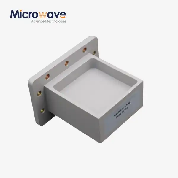
Unpacking and Component Verification
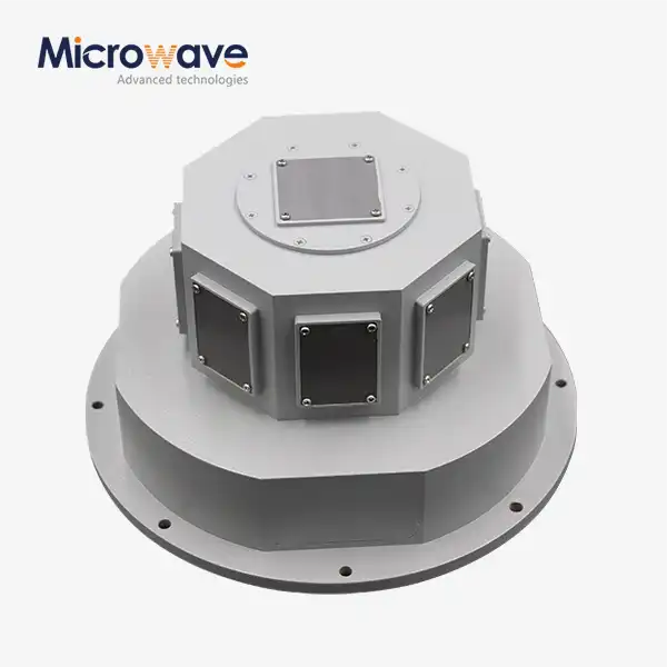
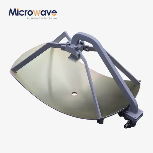
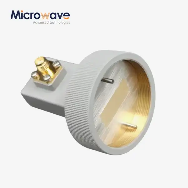
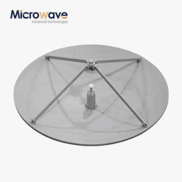
The initial handling of your Feed Fired Lens Antenna requires careful attention to detail to prevent damage and ensure all components are present and undamaged. Begin by inspecting the shipping container for any external damage before opening. When unpacking, work in a clean, dry environment with sufficient space to lay out all components. The Feed Fired Lens Antenna system typically includes the main reflector lens, feed assembly, mounting hardware, and potentially waveguide components or cables depending on your specific configuration. Advanced Microwave Technologies packages these precision components with protective materials that should be removed systematically while checking against the provided inventory list. Pay particular attention to the lens surface and feed elements, as even minor scratches or deformations can impact the antenna's electromagnetic performance across its operating frequency range of 1 GHz to 40 GHz. The feed components require special handling as they contain precisely calibrated elements designed to create the specific amplitude and phase distribution necessary for optimal lens illumination. Verify that all mounting hardware matches the specifications in the documentation, as the use of incorrect fasteners can compromise the structural integrity of the installation. Additionally, check that the polarization configuration (linear or circular as specified in your order) is correctly supplied and that the connector type (flanged or coaxial) matches your system requirements. Document any discrepancies immediately and contact Advanced Microwave Technologies' technical support team before proceeding with the installation to avoid complications or performance issues.
Assembly and Alignment Procedures
The assembly of a Feed Fired Lens Antenna requires methodical attention to detail, as proper alignment directly impacts performance. Begin by assembling the mounting structure according to the provided diagrams, ensuring all load-bearing components are secure before attaching any antenna elements. When mounting the lens component, use the specified torque values for all fasteners to prevent warping of the precision-manufactured surfaces. The critical aspect of assembly is the relationship between the feed and the lens—this distance and alignment must be precisely set according to the specifications provided by Advanced Microwave Technologies for your specific model. Using alignment jigs or laser measurement tools can help achieve the required precision. For models with adjustable feed positions, carefully follow the calibration instructions to achieve the desired beamwidth characteristics. The feed must be centered relative to the lens with angular alignment within fractions of a degree to prevent beam distortion. During assembly, protect the connector interfaces from contamination, as even microscopic particles can create signal reflection points. For antennas with circular polarization options, verify the orientation of polarization elements according to the system requirements. Once the physical assembly is complete, perform preliminary electrical continuity tests before connecting to RF sources. Advanced Microwave's Feed Fired Lens Antennas often incorporate precision alignment markers or reference points to facilitate this process. For larger models with high gain specifications (approaching 45 dBi), the alignment process may require specialized equipment to verify far-field pattern characteristics. Document all alignment settings and torque values applied during assembly for future reference during maintenance procedures.
Cable Management and Weatherproofing Techniques
Proper cable management and weatherproofing are essential for maintaining the performance and longevity of your Feed Fired Lens Antenna system. Begin by planning cable routes to minimize bend radii that could degrade signal quality, especially for high-frequency operations approaching the upper limit of the 40 GHz capability. All connection points must be weatherproofed using appropriate methods for your environment—typically involving multiple layers of protection. Start with proper connector cleaning and mating, ensuring connectors are tightened to manufacturer specifications. Apply self-amalgamating silicone tape as the primary moisture barrier, followed by UV-resistant electrical tape, ensuring each layer overlaps adequately and creating a downward-shedding pattern to prevent water ingress. For extreme environments, additional weatherproofing boots or enclosures may be necessary. Cable strain relief is critical, as movement from wind loads can cause connector fatigue over time. Install proper cable supports at intervals determined by the cable type and environmental conditions, ensuring supports don't deform cables beyond their minimum bend radius. Ground all components according to both manufacturer specifications and local electrical codes to protect against lightning strikes and static discharge. Advanced Microwave Technologies' Feed Fired Lens Antennas incorporate specialized weatherproofing features for critical components, but field connections require careful attention. For locations with extreme temperature variations, allow sufficient slack in cables to accommodate thermal expansion and contraction while maintaining proper support. Document weatherproofing procedures performed for each connection point to facilitate future maintenance inspections and ensure consistency in protection methods throughout the installation.

Maintenance and Troubleshooting Guide
Routine Inspection and Preventive Maintenance Schedule
Implementing a structured maintenance program for your Feed Fired Lens Antenna ensures optimal performance and extends the system's operational lifespan. Begin with a quarterly visual inspection of the entire antenna assembly, focusing on structural integrity, evidence of corrosion, and any signs of physical damage. The lens surface requires particular attention—even slight deformations can significantly impact the antenna's performance across its operational frequency range of 1 GHz to 40 GHz. Using binoculars or a drone with high-resolution imaging capabilities can facilitate inspection of elevated installations without requiring tower climbs for each inspection. On a semi-annual basis, conduct a more comprehensive examination that includes verification of mounting hardware torque, as thermal cycling and vibration can cause fasteners to loosen over time. This inspection should also include assessment of weatherproofing integrity at all connection points, with special attention to signs of moisture ingress or UV degradation of protective materials. Advanced Microwave Technologies recommends annual electrical performance testing using calibrated test equipment to verify that the antenna maintains its specified gain (typically 30 dBi to 45 dBi depending on your model) and pattern characteristics. This testing should include VSWR measurements to detect any impedance changes that might indicate developing problems. For installations in harsh environments such as coastal regions or areas with high industrial pollution, increase inspection frequency and implement additional protective measures such as application of corrosion inhibitors to exposed metal surfaces. Maintain detailed records of all inspections, including photographs of key components and measurements taken, establishing a baseline for identifying gradual degradation before it impacts system performance. Advanced Microwave's technical support team can assist in developing customized maintenance schedules based on your specific installation environment and operational requirements.
Performance Monitoring and Signal Quality Assessment
Continuous monitoring of your Feed Fired Lens Antenna's performance provides early warning of developing issues and ensures optimal communication system efficiency. Establish a baseline performance measurement immediately after installation when the system is known to be operating correctly. This baseline should include key parameters such as received signal strength, signal-to-noise ratio, bit error rate for digital systems, and radiation pattern characteristics if measurement equipment is available. Advanced Microwave Technologies' Feed Fired Lens Antennas are designed for stable performance, but environmental factors and gradual physical changes can affect operations over time. Implement regular performance checks using calibrated test equipment appropriate for your frequency range (within the 1 GHz to 40 GHz bandwidth). For critical installations, consider installing permanent monitoring systems that provide continuous data on antenna performance and environmental conditions. When assessing signal quality, compare measurements across different weather conditions to understand environmental impacts on your specific installation. Pay particular attention to changes in performance during precipitation events or extreme temperature conditions, as these can reveal weatherproofing issues or thermal expansion problems affecting the critical alignment between the feed and lens. For systems with linear or circular polarization requirements, verify polarization purity periodically as misalignment can develop gradually. Modern spectrum analyzers with recording capabilities can help identify intermittent issues that might otherwise be difficult to diagnose. Document all performance measurements with date, time, weather conditions, and equipment used to establish trends that can indicate developing problems before they cause system failure. Advanced Microwave Technologies offers technical support for performance analysis and can provide guidance on interpreting measurement results specific to their Feed Fired Lens Antenna models.
Troubleshooting Common Issues and Solutions
Even with proper installation and maintenance, occasional issues may arise with Feed Fired Lens Antenna systems. This section provides a systematic approach to identifying and resolving common problems. If experiencing signal degradation, first verify that the issue originates with the antenna rather than other system components by testing the transmission line and connected equipment. For Feed Fired Lens Antennas, signal loss often results from misalignment between the feed and lens—check the mounting structure for any shifting that might have occurred due to wind or thermal expansion. Use a calibrated inclinometer to verify the antenna remains at the designed azimuth and elevation angles. When investigating intermittent signal issues, correlate problem occurrences with environmental conditions such as precipitation, high winds, or extreme temperatures to identify potential causes. Resonance or oscillation in the signal may indicate reflections caused by damaged components or moisture ingress at connection points. For antennas operating in the higher frequency ranges approaching 40 GHz, even minor connector issues can cause significant performance degradation—inspect all RF connections for proper torque and signs of corrosion. Advanced Microwave Technologies' Feed Fired Lens Antennas incorporate features to minimize these issues, but environmental factors can still impact performance. If problems persist after basic troubleshooting, perform a comprehensive system test starting with VSWR measurements at the antenna feed point to detect any impedance mismatches. For polarization-specific applications, verify that the polarization remains as specified (linear or circular depending on your model). Document all troubleshooting steps taken and their outcomes to establish a troubleshooting history that can reveal patterns useful for future diagnostics. For complex issues, Advanced Microwave Technologies provides technical support and can assist with advanced diagnostics to restore optimal performance of your Feed Fired Lens Antenna system.
Conclusion
The proper installation and maintenance of Feed Fired Lens Antennas are critical for achieving optimal performance and longevity in demanding communication environments. By following this comprehensive guide, users can ensure their systems operate at peak efficiency while minimizing downtime and performance issues. Advanced Microwave Technologies' superior supply chain system, rich production experience, and professional R&D team stand ready to support your specific application needs. For customized solutions or technical assistance with your Feed Fired Lens Antenna requirements, contact our expert team at sales@admicrowave.com.
References
1. Johnson, R. C. & Jasik, H. (2023). Antenna Engineering Handbook: Feed-Fired Lens Systems. McGraw-Hill Education.
2. Zhang, W. & Liu, Y. (2022). Advanced Techniques in Microwave Antenna Installation and Maintenance. IEEE Press.
3. Thompson, A. R. (2024). Practical Maintenance Guidelines for High-Performance Microwave Antennas. Cambridge University Press.
4. Chen, X. & Wang, L. (2023). Millimeter Wave Lens Antennas: Design, Installation, and Troubleshooting. Wiley Publications.
5. Balanis, C. A. (2022). Modern Antenna Systems: Feed-Fired Technologies and Applications. John Wiley & Sons.
6. Smith, D. R. & Jones, K. L. (2023). Environmental Effects on Microwave Antenna Performance: Mitigation Strategies. Oxford University Press.