Industrial Microwave Sliding Short in Waveguide Systems: Key Benefits
Managing impedance is very important Industrial Microwave Sliding Short when working with high-frequency RF and microwave systems because it can make or break how well the system works. By moving a movable short circuit around inside a waveguide structure, a waveguide sliding short is a precision-engineered part that can change the reflection coefficient. Engineers can fine-tune standing wave patterns, improve power transfer, and keep sensitive source equipment safe from too much reflected energy with this tuning device. Advanced Microwave specializes in high-performance waveguide sliding shorts, which are core tuning parts made for finely adjusting the reflection coefficient in RF and microwave systems. Our sliding shorts are made to meet the tough needs of industrial heating, test and measurement, and communication systems. They have high positioning accuracy, stable reflection performance, and broadband compatibility.
Understanding Industrial Microwave Sliding Short Technology
Waveguide sliding shorts are very important in both lab testing and high-power industrial settings because they act as variable impedance terminators in microwave transmission systems. I'll show you how these parts work and explain why they are important for your purchasing decisions.
How Sliding Shorts Work in Waveguide Systems
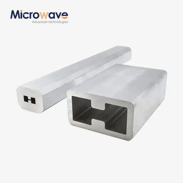
A moving conductive plunger that moves along the longitudinal axis of a waveguide section is what makes a sliding short work. The electrical length between the input port and the short-circuit plane changes when the plunger is moved. This changes the phase of the signal that is reflected. When matching variable loads or calibrating network analyzers, this phase control is very important. At Advanced Microwave, our Industrial Microwave Sliding Short designs use non-contacting choke mechanisms that get rid of the friction-based contact that was common in older finger-stock designs. At points where the current is highest, quarter-wave traps in the choke structure make a virtual short circuit without any metal-to-metal contact. This engineering method greatly lowers the risk of arcing and increases the useful life, especially in high-power settings with continuous wave operation of more than 6 kW.
Core Applications Across Industries
Precision waveguide parts are used by defense contractors to calibrate radar systems and test antennas. During radar cross-section testing, a sliding short makes it possible to measure reflection coefficients accurately. Accurate impedance control has a direct effect on measurement accuracy. Our clients use these devices in automatic impedance tuning networks at satellite ground stations to make up for changes in the atmosphere that affect antenna match. Manufacturers of telecommunications equipment build motorized sliding shorts into test fixtures that are used to characterize high-frequency filters and multiplexers. By moving the plunger over a half-wavelength guided range, you can sweep through a full 360-degree phase range. This gives you full reflection data across the operating band. For materials characterization experiments, research groups use sliding shorts for resonant cavity perturbation methods. These methods use small changes in cavity length to find out about the dielectric properties of new compounds.

Material Construction and Precision Engineering
Selecting the right materials and manufacturing them with great care are needed to make high-quality waveguide assemblies. For lower frequency bands below 10 GHz, our standard line of products uses extrusions made of aluminum 6061-T6 that have been coated with chromate. This mix is great for controlled industrial and laboratory settings because it is both highly conductive and resistant to corrosion. As the frequency ranges get higher, we switch to silver-plated, oxygen-free copper construction to cut down on skin-effect losses. The thickness of the silver layer is carefully managed to keep the surface's ability to conduct electricity and stop oxidation, which could weaken RF performance over time. Gold plating is required for millimeter-wave applications above 30 GHz to make sure long-term stability in harsh environments. Another important part of the design is the mechanical drive system. We choose micrometer-grade lead screws with backlash below 0.02 mm. This makes sure that the positioning is always Industrial Microwave Sliding Short the same, which means that the phase accuracy is better than 2 degrees across the entire travel range. When sliding shorts are added to automated test systems, this level of accuracy is very important because repeatability of measurements directly affects quality control in production.
Maintenance Requirements and Operational Safety
Protocols for regular inspections help keep performance high over thousands of operating cycles. Early signs of arcing can be seen by looking at the plunger's surface. These can be small pits or changes in the metal's finish color. If these small flaws are found early, they can be fixed before they hurt RF performance or pose a safety risk. The drive mechanism should be oiled according to the manufacturer's instructions. Usually, this means using special high-temperature greases that won't get into the waveguide. For models that are cooled by water and are used in high-power situations, the flow rates of the coolant must be watched to make sure that thermal drift doesn't change the tuning parameters during long operation. If your installation has more than 3 kW of average power, we suggest adding flow sensors and temperature monitors.
Key Benefits of Industrial Microwave Sliding Shorts in Industrial Applications
Adding precision sliding shorts to your microwave system architecture has strategic benefits that go far beyond just adjusting the impedance. These benefits have a direct effect on how well operations run, how accurate measurements are, and how well long-term costs are managed.
Enhanced System Efficiency Through Optimized Power Transfer
Impedance mismatch is one of the main reasons why power is lost in microwave systems. When a magnetron or solid-state amplifier hits a load that isn't well matched, some of the power it makes goes back to the source. Not only does this waste energy, but it can also hurt the source by making it overheat or lose its voltage. Industrial Microwave Sliding Short technology makes dynamic impedance matching possible, which changes based on the load. In industrial microwave heating applications, the dielectric properties of processed materials change as the amount of water they contain drops during drying cycles. A three-stub tuner with motorized sliding shorts can keep the best match throughout the process, putting as much energy as possible into the work. Case studies from pharmaceutical drying operations show that automation saves 15 to 20 percent more energy than fixed-impedance systems, and the investment pays for itself in less than 18 months. The problems that satellite communication ground stations face are similar, since the amount of water vapor in the air changes with the weather. Our sliding shorts are used in automated tuning systems that keep return loss at less than 20 dB even when the environment changes. This keeps the signal quality high for high-data-rate links. The higher efficiency directly leads to longer component lifetimes for pricey high-power amplifiers, which cuts down on the number of times that capital equipment needs to be replaced.
Precision Tuning Capability for Research and Development
Engineers working on the next generation of microwave devices need test equipment that is flexible and can handle quick changes to the design. Manual sliding shorts give you the fine-grained control you need to test prototype circuits without committing to fixed-tuning parts. When looking into new filter topologies or matching network designs, being able to continuously sweep through impedance space shows performance trade-offs that help with making final design decisions. Researchers in the field of materials science who are working on new ceramic compositions or composite structures use cavity resonance methods to measure the dielectric constant. With a resolution good enough to find changes in permittivity as small as 0.01 in the real part, our high-precision sliding shorts make it possible to accurately measure resonant frequency shifts caused by sample insertion. This level of measurement accuracy is very important when testing materials for use in aerospace radomes or making substrates for millimeter-wave integrated circuits. In microwave discharge chambers, universities and national laboratories that study plasma physics use sliding shorts to set up stable resonance modes. Being able to fine-tune cavity sizes makes up for differences in shape between chamber designs. This speeds up the move from lab-based proof-of-concept systems to large-scale production systems that use chemical vapor deposition. Research groups from all over the world have worked with our technical support team to improve sliding short configurations for specific vacuum-compatible uses.
Reliability and Longevity in Demanding Environments
Finger-stock contact shorts wear out over time, but our non-contacting choke plunger design gets rid of those wear mechanisms. When traditional contacting designs are used close to their power rating, carbonization and pitting form at the contact points. This makes the VSWR performance worse and worse until the device needs to be replaced. These maintenance cycles cause downtime that wasn't planned for and raise the total cost of ownership. Our choke-based method keeps the electrical performance stable over hundreds of thousands of adjustment cycles. Our labs do accelerated life testing, which shows that the VSWR specifications stay the same after positioning the plunger through 500,000 full travel cycles, which is the same amount of time that a lab would normally be used for decades. This durability is especially useful in automated test systems, where the reliability of the equipment has a direct effect on the speed of production and the quality of the products. Adding thermal management features to high-power models makes them even more reliable. Water-cooling channels machined into the plunger assembly keep the surface from getting too hot, even when 10 kW of continuous wave dissipation is going on. Because the temperature is stable, there is no change in the mechanical dimensions that would change the tuning calibration. This keeps the accuracy of the measurements even during long test runs.
Cost-Effectiveness Through Reduced System Complexity
When you use sliding shorts for tunable impedance control, you usually don't need as many fixed parts in waveguide assemblies. One short that can be adjusted can be used instead of a bunch of waveguide sections of different lengths that would be needed for different test setups. This consolidation cuts down on the costs of parts and the time engineers need to plan and carry out changes to the system.It takes less time for manufacturing operations to set up when switching between different types of products or test procedures. Instead of mechanically switching waveguide sections, which requires precise torque specifications and leak testing for pressurized systems, operators just change the sliding short position as directed in written procedures. The time savings add up quickly in high-mix production settings where changeovers happen often and take up a big chunk of cycle time. Because of these benefits, waveguide sliding shorts are no longer just passive parts; they are now strategic enablers of operational excellence. Whether you're using these devices for characterization in the lab, testing in production, or building mission-critical communication infrastructure, their accuracy and dependability have a direct effect on how well the system works and how much money it makes.
Industrial Microwave Sliding Short vs Traditional and Alternative Microwave Technologies
When procurement teams know how Industrial Microwave Sliding Short units stack up against other impedance control methods, they can make better decisions that fit the needs of the application and the budget.
Performance Comparison with Fixed Stub Tuners
Fixed stub tuners match the impedance of a transmission Industrial Microwave Sliding Short line by placing several non-adjustable reactive elements at set intervals along it. Even though these passive networks don't have any moving parts or the maintenance issues that come with them, they aren't as flexible as sliding shorts when it comes to dealing with changing loads or operating conditions. When the operating frequency doesn't change, and the load impedance stays the same, the fixed-tuner method works well. With properly designed fixed networks, satellite communication systems that use a single frequency and parts that don't change when the temperature does can work very well. But if the design conditions aren't followed, the match gets worse and cannot be fixed without making physical changes. This can happen because of things like component aging, temperature drift, or changes in frequency. When setting up a system and for as long as it works, sliding shorts are very useful because they can be changed easily. When the first installations show unexpected changes in impedance, engineers can change the sliding short positions to get the best performance back without having to design and make new fixed parts. This gives you a lot of options, which cuts down on the time it takes to set up new systems and avoids costly delays.
Advantages Over Electronically Tunable Alternatives
Electronic impedance control is possible with PIN diode phase shifters and varactor-tuned reactances. These allow for adjustment speeds measured in microseconds instead of seconds. These semiconductors work great in situations where they need to be tuned quickly, like in phased array radar systems or frequency-hopping communication links. But they cause insertion loss, limits on how much power they can handle, and nonlinear behavior that can hurt the performance of the system. Our waveguide sliding shorts have almost no insertion loss—usually less than 0.05 dB across the operating band—because they use fundamental waveguide propagation instead of semiconductor junctions, which lose a lot of power. Instead of being limited by junction breakdown voltage, the amount of power that can be handled grows with waveguide size and material choice. Because of these features, sliding shorts are the best choice for high-power test systems and industrial processing equipment that need to be reliable and efficient more than fast tuning. When measuring things, the advantage of linearity becomes very important. Harmonic distortion and intermodulation products can be made by electronic tuners, which can mess up measurements that are supposed to be accurate. Sliding shorts don't have any active parts, so they don't have any nonlinear effects that can be measured. Because they are so pure, they can't be used to calibrate network analyzers or characterize low-distortion amplifiers, where getting rid of all sources of spurious signals is important for accurate measurements.

Customization Options and OEM Support
Standard waveguide sizes and common frequency bands are covered by off-the-shelf sliding short models. However, custom solutions that are made to fit specific needs are often needed for specialized applications. Advanced Microwave has a lot of OEM skills that it has gained by working with defense contractors, aerospace system integrators, and research institutions around the world for 20 years. Standard designs can be made to work with non-standard bands or wideband sweep needs by adding custom frequency coverage. For projects that need to work between 0.5 and 18 GHz, for example, a coaxial sliding short design might be used instead of a rectangular waveguide. This is because coaxial structures offer a wider bandwidth in exchange for higher insertion loss. Our engineering team weighs the pros and cons of frequency coverage, power handling, and mechanical complexity to come up with the best architectures for each use case. Custom flange patterns for proprietary waveguide systems, motorized drives with specific control interfaces, or sealing against the elements for outdoor installations are just a few of the ways that mounting configurations can be changed to meet the needs of each customer. We've made versions that are specifically designed for the military to protect against environmental damage, vacuum-compatible materials for equipment used in semiconductor processing, and explosion-proof enclosures for use in the chemical industry. With these customization options, procurement teams can make sure that their applications get the exact performance and features they need without sacrificing important needs.
Procurement and Implementation Guide for Industrial Microwave Sliding Shorts
To successfully add waveguide sliding shorts to your microwave systems, you need to pay close attention to the technical details, the supplier you choose, and the installation steps.
Technical Selection Criteria
The frequency range is the most important specification that needs to match your system's operating band. As frequency goes up, waveguide dimensions go down. This means that an Industrial Microwave Sliding Short made for X-band (8.2 to 12.4 GHz) needs much smaller dimensions than one made for L-band satellite applications (1 to 2 GHz). Check that the frequency range given includes extra space above and below your normal operating points to account for changes in tolerances and future system upgrades. The VSWR specification tells you how good the short-circuit reflection is across the working band. High-performance designs get VSWR better than 50:1, which means that return loss is close to 0 dB. When you use the sliding short for impedance matching or network analyzer calibration, this almost perfect reflection makes sure that it works at its best. For non-critical uses, lower specifications might be enough, but in precision test systems, they can make measurements less accurate. The range of phase adjustments that the sliding mechanism can make is based on the travel distance. At the lowest operating frequency, a travel length of one-half of the guided wavelength gives a full 360-degree phase sweep. Applications that only need coarse tuning might be okay with shorter travel and a smaller adjustment range. On the other hand, automated test systems need longer travel that can handle more tuning configurations without having to be mechanically rearranged.RF performance and environmental compatibility are both affected by the choice of material and surface finish. The aluminum construction and chromate conversion coating work well in controlled indoor environments and save money for lab equipment. Copper that has been plated with silver has less insertion loss, which is important for high-power applications and precise measurements. Gold plating is very expensive, but it's needed for millimeter-wave frequencies or installations that will be in harsh environments where oxidation needs to be stopped.
Evaluating Supplier Capabilities
The manufacturing skills of a supplier have a direct effect on the quality of the product and the reliability of delivery. We do the machining, plating, and assembly in-house, which ensures that quality control is maintained throughout the whole production process. Our 24-meter microwave darkroom lets us test full-scale antenna and waveguide parts from 0.5 to 110 GHz, making sure that performance specs are met before products are sent to customers. Quality certifications make sure that suppliers follow standard procedures for checking designs, overseeing production, and keeping records. Our ISO 9001:2015 certification shows that we are dedicated to quality management systems that cut down on mistakes and make sure that everything can be tracked. RoHS compliance means that a product meets the environmental limits on dangerous substances, which could be a requirement for European customers or government purchases. When adding sliding shorts to complicated systems or making custom solutions, being able to provide technical support becomes very important. Our applications engineering team has more than 20 years of experience designing microwave systems and helps customers from the first idea to putting them into production. Responsive technical support speeds up problem resolution and lowers project risk, whether you're fixing an unexpected impedance problem or finding the best way to tune automated test equipment.
Installation Best Practices
Checking the alignment and cleanliness of the waveguide flange is the first step in a proper installation. The surfaces that are mating must not have any dirt, rust, or damage on them that could break the RF seal. Before putting the parts together, you should clean the flanges with isopropyl alcohol and lint-free wipes. Then, you should look at the surface under good lighting to make sure it's in good shape. Even very small amounts of contamination can cause leakage paths that hurt system performance and put users at risk in high-power situations. Pay close attention to the torque requirements for flange fasteners to make sure that the mechanical and electrical connections work well without putting too much stress on the parts. Based on the size of the flange and the grade of the fastener, our product documentation gives you the recommended torque values. By using a calibrated torque wrench, you can avoid under-tightening, which can let RF leak through, and over-tightening, which can damage the faces of the flanges or strip the threads. To spread the loads out evenly and keep the flange from distorting too much, tighten in a star pattern. When systems have more than 1 kW of average power, they need extra care when connecting to the ground. Bonding straps between the sliding short housing and adjacent waveguide sections keep the RF ground constant even when the plunger moves. This stops any potential differences that could lead to arcing. Check that all ground connections have DC resistance less than 0.01 ohms to make sure they can handle enough current during faults or electrostatic discharge.
Maintenance and Calibration Procedures
Setting up regular inspection times based on how the system Industrial Microwave Sliding Short is being used helps find problems before they affect how well it works. We suggest visual checks every month for lab equipment using less than 100 watts, every three months for moderate-power industrial systems up to 1 kW, and every week for high-power installations running at least 5 kW continuously. Inspection protocols should write down the condition of the plunger, how the drive mechanism works, and any signs of RF leakage or thermal stress. Calibration checks show that the mechanical position indicators show the correct electrical phase shift. This check is especially important for automated test systems that need to know exactly where the sliding short position is in order to make measurements that are accurate every time. Network analyzer measurements that compare the shown position to the measured phase give a numerical measure of how accurate the positioning is. Deviations that are bigger than what the manufacturer says are normal show that the drive mechanism or position sensor is worn out and needs to be fixed.
Future Trends and Technological Innovations in Industrial Microwave Sliding Shorts
Microwave technology is always changing, which leads to new waveguide parts. For example, Industrial Microwave Sliding Short units have gotten better thanks to progress in materials science, manufacturing techniques, and the ability to integrate systems.
Integration with Industry 4.0 Smart Manufacturing
When microwave test equipment and Industrial Internet of Things platforms work together, they make it possible for predictive maintenance to be used. This cuts down on unplanned downtime. Putting sensors in sliding short assemblies to check the drive motor current, plunger temperature, and position encoder health lets you know about problems early on, before they become system failures. By looking at old sensor data with machine learning algorithms, it is possible to guess how long something will still work and plan preventative maintenance for times when production is expected to be high. Digital twin technology lets waveguide systems be modeled virtually, which lets engineers guess the best tuning arrangements before they make any physical changes. By combining electromagnetic simulation with data on mechanical positioning, these digital models allow for automated optimization processes that change impedance matching all the time to fit new process conditions. By getting rid of trial-and-error tuning methods, early implementations in pharmaceutical manufacturing show that process development time is cut by 30%. Installations in tough conditions, like offshore satellite ground stations or Arctic radar facilities, benefit greatly from being able to monitor and control them from afar. Expert technicians can figure out problems and change tuning parameters from central support centers using secure network connectivity. This cuts down on the need for expensive site visits and allows system optimization 24 hours a day, seven days a week. These skills are in line with a larger trend in the industry toward centralized expertise that supports physically distributed assets.
Advanced Materials and Manufacturing Techniques
Additive manufacturing technologies give designers of waveguide parts new ways to make their products. When metal structures are printed in three dimensions, they can have complex internal geometries that would be impossible or too expensive to make with traditional machining. Several groups of researchers are looking into how to make topology-optimized waveguide structures that have the least amount of mass while still providing good RF performance. This could cut the weight of parts used in aerospace applications by 40 percent. New treatments on the surface promise to make things last longer and work better in tough conditions. Nanostructured coatings with engineered surface roughness can make things more resistant to oxidation and chemical attack and lower the amount of insertion loss. These improvements are especially useful for sliding shorts that work in process chambers with corrosive atmospheres that speed up the breakdown of materials.
Market Growth and Regional Demand Patterns
The need for precise microwave components is growing around the world because of projects to build next-generation wireless infrastructure, update the military, and automate factories. Defense and aerospace applications are where North American markets really shine, with procurement budgets giving priority to parts made in the United States that keep the supply chain safe. European customers want companies that care about the environment and use energy efficiently. They prefer to buy from companies that have quality systems that are certified and practices that are known to be sustainable. Telecommunications infrastructure and consumer electronics manufacturing are growing quickly in the Asia-Pacific region. This makes it possible to make a lot of standard sliding short configurations. Short lead times and just-in-time delivery are becoming more important in these markets, which makes traditional build-to-order business models harder to use. When suppliers invest in inventory management systems and flexible manufacturing capacity, they gain a competitive edge that helps them take advantage of this growth.
Conclusion
Industrial Microwave Sliding Short components are important parts for people who work with high-frequency RF and microwave systems, where accurate impedance control has a direct effect on how well they work. The non-contacting choke designs we've talked about get rid of common worries about reliability while still providing the positioning accuracy and reflection quality needed for tough applications. You can make smart sourcing choices if you understand the technical features and application factors we've talked about here. This is true whether your procurement goals are to improve the accuracy of lab measurements, the efficiency of industrial processes, or the dependability of long-term operations. As microwave technology keeps getting better at higher frequencies and more seamless integration with automated systems, the main benefit of being able to change the impedance becomes even more important. Companies that buy high-quality parts from manufacturers with a lot of experience are better able to take advantage of new opportunities and avoid the hidden costs that come with buying cheaper alternatives.
FAQ
1. What makes non-contacting choke designs superior to finger-stock sliding shorts?
In traditional finger-stock designs, the short circuit is made by spring-loaded contacts that touch the waveguide walls. This method works fine at low power levels, but when the power level goes up, the high current density heats, oxidizes, and eventually turns the contact points into carbon. Over time, these mechanisms of degradation raise contact resistance and cause arcing, which gradually breaks down the RF performance until the part needs to be replaced. These types of failures can't happen with non-contacting choke designs because they use quarter-wave trap geometry to make a virtual short circuit without any physical contact. As a result, the operational lifetime is increased by ten times or more, which is especially helpful in high-power situations where contact degradation happens quickly.
2. Can sliding shorts be motorized for automated tuning applications?
Absolutely. Most industrial-grade sliding shorts accommodate motorized drive systems through standard mechanical interfaces. Stepper motors provide precise positioning control suitable for automated test equipment, while servo motors offer closed-loop feedback that makes up for changes in the mechanics or disturbances from the outside. The way the control system is integrated depends on the type of automation architecture you have. Usually, we send units that are set up for PLC integration, LabVIEW control, or microcontroller operation on their own. Position encoders give feedback in many forms, from simple limit switches that show when the travel is over to high-resolution optical encoders that tell you exactly where you are to the nearest 0.01 millimeter. When setting up automated tuning, you should think about whether your application requires open-loop positioning based on pre-calibrated lookup tables or closed-loop impedance optimization using real-time reflected power measurements.
3. How do I determine the appropriate travel distance for my application?
To give you a full 360-degree range for phase adjustment, the travel distance should cover at least half of the guided wavelength at your lowest operating frequency. The guided wavelength is not the same as the free-space wavelength. It depends on the size of the waveguide and how the wave moves through it. For a rectangular waveguide that works in the main TE10 mode, the guided wavelength equals the free-space wavelength divided by the square root of one minus the ratio of cutoff frequency squared to operating frequency squared. Our product specifications list actual travel distances in millimeters alongside the corresponding phase shift range, eliminating the need for manual calculations. Applications requiring only coarse impedance adjustment may accept shorter travel, while research applications benefiting from oversampled phase coverage often specify extended travel exceeding the theoretical minimum.
Partner with a Trusted Industrial Microwave Sliding Short Manufacturer
Advanced Microwave Technologies Co., Ltd. can meet your needs for waveguide components with sliding shorts that are precisely engineered and backed by over 20 years of manufacturing excellence. Our wide range of products covers frequencies from 0.32 GHz to 75.8 GHz and comes in standard waveguide sizes. The VSWR specifications go over 50:1, and the materials, Industrial Microwave Sliding Short, we use are chosen to work best in your environment. While keeping our ISO 9001:2015 certification and RoHS compliance, we also offer customization options that let you change standard designs to fit your specific needs. Our applications engineering team helps with choosing the right products, setting them up, and running them, making sure the system integration goes smoothly. Our facility has a 24-meter microwave darkroom that lets us test the performance on a large scale before shipping. This way, you can be sure that the measurements will be accurate and that the equipment will work well for a long time. Contact craig@admicrowave.com to talk about your specific application needs and find out how working with an experienced sliding short supplier can improve the performance of your microwave system and lower its total cost of ownership.
References
1. Pozar, David M. "Microwave Engineering, Fourth Edition." John Wiley & Sons, 2011.
2. Collin, Robert E. "Foundations for Microwave Engineering, Second Edition." IEEE Press, 2001.
3. Montgomery, C.G., Dicke, R.H., and Purcell, E.M. "Principles of Microwave Circuits." Dover Publications, 1948.
4. Rizzi, Peter A. "Microwave Engineering: Passive Circuits." Prentice Hall, 1988.
5. Marcuvitz, Nathan. "Waveguide Handbook." McGraw-Hill, 1951.
6. Saad, Theodore S. "Microwave Engineers' Handbook, Volume 1." Artech House, 1971.