How Do low loss bandpass filters Reduce Signal Attenuation?
Low loss bandpass filters achieve minimal signal attenuation through careful engineering that addresses multiple loss mechanisms simultaneously. These specialized components utilize high-conductivity materials like silver-plated brass or aluminum housings that reduce skin-effect losses during signal propagation. The filters employ resonant cavity designs with exceptionally high unloaded Q-factors—typically ranging from 500 to 5,000—which enable selective frequency passage with insertion loss below 1.0 dB. Premium dielectric materials and optimized coupling structures ensure that desired signals traverse the passband with minimal energy dissipation. By combining precision machining tolerances, low-PIM (Passive Intermodulation) design techniques, and mathematically optimized topologies like Chebyshev or Butterworth responses, low-loss bandpass filters preserve signal strength while providing sharp stopband rejection that eliminates interference without compromising the integrity of mission-critical communications.
Introduction
Signal integrity affects system performance, link budget margins, and operational dependability in contemporary RF and microwave systems. Communication designs utilise bandpass filters to let desired frequency bands through while rejecting out-of-band interference that might damage receiver sensitivity or violate spectrum. Conventional filtering methods frequently increase insertion loss, which is problematic when operating margins are low or power efficiency is crucial.
How low-loss bandpass filters minimise signal attenuation while preserving strong filtering features becomes more important for procurement engineers and system designers. This differential is important for defence radar systems that need maximum detection range, satellite ground stations near thermal noise floors, and 5G infrastructure where every tenth of a decibel impacts coverage radius and capacity. Understanding attenuation reduction techniques helps source products that balance technical performance, cost, customisation, and supply chain needs.
Understanding Low Loss Bandpass Filters
Low-loss bandpass filters are a special type of passive RF part that is designed to send signals only within a certain frequency range while wasting as little energy as possible in the passband. General-purpose filters can handle insertion losses of up to 2 to 3 dB, but these precision devices usually have insertion losses below 1 dB because they pay close attention to the materials they use, how they are built, and how well they are made.
Defining Characteristics and Performance Parameters
The performance range of these filters is set by three basic factors. Insertion loss measures how much signal power is lost within the passband. The lower this number, the better the filter keeps signal strength. Bandwidth tells you what range of frequencies the filter keeps its passband properties over. Tighter bandwidths need more complex resonator designs. Frequency response describes how the filter acts across the whole spectrum, including how flat the passband is, how high the transitions are, and how deep the stopband rejection goes.
Operating Principles That Minimize Attenuation
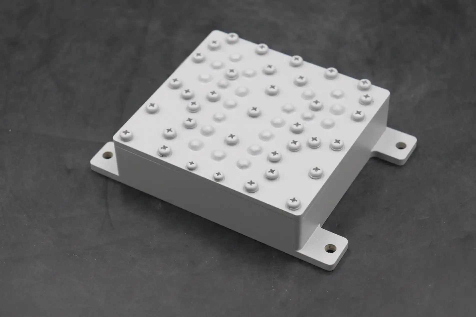
Attenuation reduction is based on making the resonator quality factor (Q) as high as possible while reducing resistance losses. In coaxial designs, electromagnetic energy moves in TEM mode between the inner and outer conductors. Most of the energy is lost because metal surfaces don't conduct electricity very well. If you compare bare brass or copper to high-quality silver plating, which is usually 3 to 5 micrometers thick, you can see that the surface resistance losses are much smaller. By using air-filled cavities, waveguide versions completely get rid of dielectric losses, achieving unloaded Q-factors above 10,000 at microwave frequencies. The coupling iris measurements and resonator spacing are carefully optimized using electromagnetic modeling to reach the desired bandwidth without adding any discontinuities that would cause loss.
Advantages Over Conventional Filtering Solutions
In more than one way, these precision filters work better than alternatives like ceramic or lumped-element filters. The signal quality stays the same because the minimum passband ripple and group delay variation keep the modulation properties that are needed for digital messaging. In low-noise amplifier chains, the noise figure input stays very small, which keeps the receiver's sensitivity from going down. Power efficiency goes up a lot in transmitter applications, where every decibel of insertion loss means more wasted DC power and more heat management needs to be done. This is especially important for satellite payloads and airborne platforms that have to stay light and cool.
Key Design Principles Behind Low Loss Bandpass Filters
To get the least amount of loss, you need to pay careful attention to both the theory and practice of electromagnetic design. Narrow bandwidth vs. acceptable size, sharp selection vs. low insertion loss, and high power handling vs. small form factors are all goals that engineers have to balance.
Controlling Insertion Loss Through Topology Optimization
Loss efficiency is based on choosing the right filter design. Chebyshev filters give you sharper transition bands, but they also add passband ripple that shows energy being mirrored instead of lost. Butterworth topologies make passband flatness better, but they slow down rolloff rates in exchange. For strong rejection, elliptic designs put transmission zeros in the stopband. However, they need extra resonators that add to the loss. Designers look at the needs of the application to choose designs that offer the best balance of trade-offs. They know that adding another filter order increases selectivity while decreasing insertion loss for low loss bandpass filters.
Material Properties That Minimize Energy Dissipation
Premium materials directly deal with the basic causes of loss. High-purity OFHC (oxygen-free high-conductivity) copper substrates are better at conducting electricity than regular alloys. The width of silver plating is carefully controlled—too thin, and pinholes will affect how well it works, and too thick, and resources will be wasted without any visible benefit. In microstrip versions, dielectric surfaces use low-loss tangent materials like PTFE composites that keep their electrical properties fixed at high and low temperatures. Materials that aren't magnetic stop hysteresis losses and PIM generation, which happen when ferromagnetic parts are used at high power levels.
Precision Frequency Response Tuning
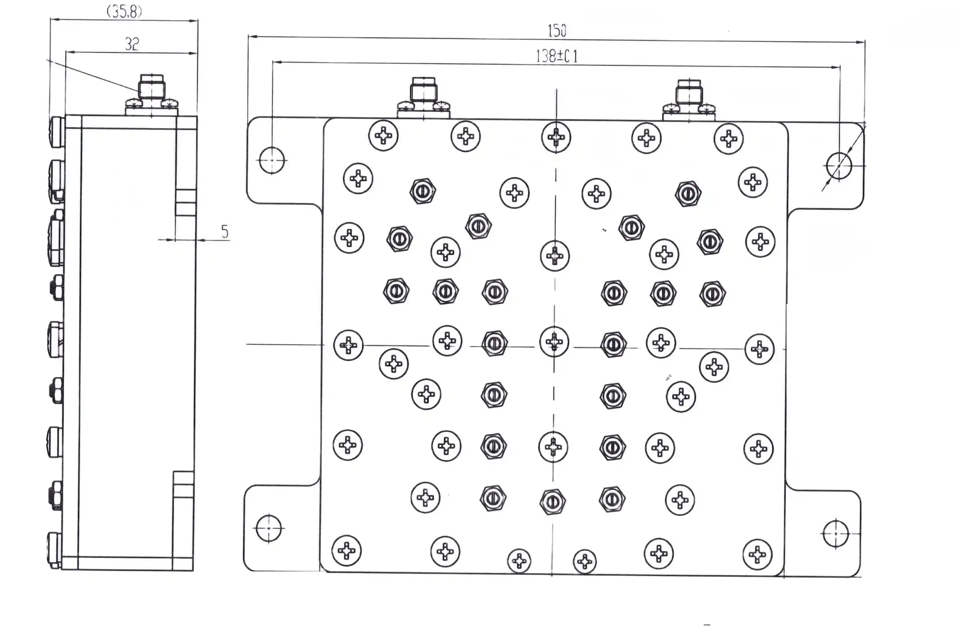
Variations in manufacturing need post-production tweaking to achieve claimed performance. Changing the effective electrical length requires tuning screws in resonant holes. This compensates for production tolerances and material attributes. Multiple tests with a Vector Network Analyser demonstrate that this approach maintains center frequency accuracy within ±0.1% and achieves established insertion loss targets. The cavity coupling strength and resonator spacing determine out-of-band rejection. While designing, high-tech electromagnetic simulation tools assist designers in locating the ideal values for these parameters before costly sample production.
Full-wave electromagnetic modelling techniques that simulate Maxwell's equations over complex three-dimensional geometries are increasingly employed for design validation. These tools estimate insertion loss from wire resistance, dielectric dissipation, radiation leakage, and mismatch effects. This helps designers improve structures digitally before prototyping. Expected and measured passband values now agree within 0.1 dB due to enhanced simulation accuracy. This greatly reduces development time and hardware expenses.
Comparing Low Loss Bandpass Filters with Other Filter Types
To choose the right filtering technology, you need to know how the different methods solve problems in different applications. There are big differences in performance, physical limitations, and cost structures between filter groups. This means that making an informed choice is very important for the successful buying of low-loss bandpass filters.
Performance Distinctions Across Filter Categories
High-loss bandpass filters that use ceramic resonators or mixed elements give up insertion loss performance—often more than 3–4 dB—in order to be smaller and cheaper per unit. These work well for consumer uses where extra loss is okay because the link budget allows it, but professional use needs better efficiency. Notch filters have deep nulls at certain frequencies that interfere, but they don't have the broad stopband rejection that is needed for full interference control. Cavity-based coaxial and waveguide filters have very different levels of performance. Coaxial versions are the best balance of size and performance for applications below 10 GHz, while waveguide structures rule in high-power and millimeter-wave regimes because they can handle more power and have much lower loss, which means they need to be bigger.
Selection Criteria for Mission-Critical Applications
Buying decisions depend on how well the filter's features match the needs of the system. To get the best G/T (gain-to-noise-temperature) ratios, satellite communication ground stations look for very low insertion loss. They often accept bigger waveguide filters, even if they are harder to install. Cellular base station duplexers need small coaxial designs that can handle tens to hundreds of watts of power all the time and fit into boxes with limited room. To get the widest range of detection, radar systems need to be able to handle both low loss and high power. For L–X-band applications, coaxial filters are usually used, while waveguide implementations are used for higher frequencies. Highly stable, low-PIM filters keep unwanted signals out of testing and measurement equipment while sensitive classification work is being done.
Practical Integration Considerations
System compatibility includes more than just electrical specs; it also includes environmental scores, supply chain factors, and mechanical connections. Connector types must meet the current wiring: for coaxial types, they must be SMA, N-type, or 7/16 DIN; for higher frequencies, they must be standard waveguide flanges like WR-90 or WR-62. When sites are outside where temperatures can range from -40°C to +70°C, operating temperature ranges need to be carefully thought out. For platforms in the air, performance at higher altitudes is important because lower air pressure changes corona discharge thresholds in high-power applications.
Applications and Case Studies of Low Loss Bandpass Filters
Real-life examples of how these precise parts are used show how they solve real engineering problems in a wide range of fields. Performance changes directly lead to better system performance and business benefits for networks utilizing low loss bandpass filters.
Critical Applications Across Industry Sectors
Cellular infrastructure has massive rollout numbers, and even tiny dB changes may affect network performance. In 5G massive MIMO base stations, each antenna element's filters must have low loss to maintain the perfect balance between broadcast power and reception sensitivity for enhanced beamforming. Satellites utilise filters to segregate uplink and downlink frequencies in full-duplex operation. Extra loss reduces connection margin, which limits data rates and service availability in adverse weather. Defence radar sites utilise filters to keep receivers sensitive to emitter noise while sending and receiving simultaneously for continuous-wave illumination modes. Industrial IoT networks utilise selective filtering to eliminate interference from neighbouring channels that might hinder low-power sensor transmissions in busy ISM bands.
Documented Performance Improvement Case Study
A company that puts together communication systems had trouble with co-site interference that affected a C-band satellite ground station sensor for a long time. The first ceramic filter had 2.8 dB of insertion loss and not enough adjacent channel rejection, which made the system G/T worse by 0.9 dB. We made a custom waveguide bandpass filter that has an insertion loss of 0.4 dB and a stopband rejection of 80 dB at frequencies that interfere. Using a spectrum analyzer and noise figure meter to measure after installation showed that the system's G/T went up from 31.2 dB/K to 33.7 dB/K, which is a 2.5 dB gain. This improvement led to a 15% rise in the available link margin, which let the operator keep the full data flow during rain fade events that used to slow down service.
Verification Through Rigorous Testing
Our advanced measuring tools, such as a 24-meter anechoic chamber and network analysis equipment that can go up to 110 GHz, allow us to fully verify claims about filter performance. Environmental stress testing according to MIL-STD-810 guidelines shows that the mechanical stability can withstand changes in temperature, vibration, and humidity. Space-qualified units go through high-power tests to make sure they meet the corona discharge and multiplication thresholds. X-ray fluorescence research confirms the thickness and makeup of the plating. Procurement experts can be sure that the performance standards will be met in the field thanks to these quality assurance procedures.
Procurement Guide for Low Loss Bandpass Filters
To find precision RF components, you have to figure out technical specs, what the seller can do, your customization choices, and the quality control rules. When procurement of low-loss bandpass filters is done right, performance needs are balanced against budget limits and delivery dates.
Identifying Qualified Supplier Partners
On the global market, there are well-known companies that are known for their tech skills and high quality. Mini-Circuits has a large catalog with a lot of choices that are good for testing and small to medium production runs. MACOM specializes in high-frequency solutions for use in aerospace and defense. Skyworks makes combined filter units for infrastructure that uses wireless technology. For measuring purposes, Keysight makes precise parts that are made for labs. TDK makes small solutions with a focus on miniaturization. Each supplier has their own strengths, such as being able to offer products from a catalog versus making custom orders, specializing in a certain frequency range, or having industry certifications like ITAR compliance for defense applications.
Customization Process and Lead Time Expectations
It's important to be able to customize standard store items because they don't always meet the exact needs of complex systems. Usually, the buying process starts with a technical question that lists center frequency, bandwidth, insertion loss goals, power handling needs, and connection preferences. Within one to two weeks, engineering teams react with basic designs, S-parameter simulations, and mechanical drawings to help with the first feasibility assessment. Once the design is approved, making the prototype takes three to five weeks, which includes manufacturing, tuning, and full electrical testing. Once the process for making tools and fine-tuning them works well, production orders can be increased easily. Delivery usually takes 6 to 10 weeks, depending on the number of items and how complicated they are. When project deadlines get squished out of the blue, expedited processing can meet urgent needs.
Cost Structures and Quality Assurance
Technical value, material cost, product difficulty, and order volume determine prices. Prototypes cost more because engineers spend more time and money putting them up. Coaxial designs cost $500–$3,000, and waveguide designs cost $2,000–$10,000. Higher production numbers decrease costs with amortised tooling and efficient procedures. Unit expenses might reduce by 40–60% when making more than 100 items. Certifications like ISO 9001:2015 and RoHS compliance provide fundamental peace of mind, while military standards like MIL-STD-202 ensure product performance in hostile conditions. Requesting comprehensive test data packages, including S-parameter files, mechanical inspection records, and material certifications, lets you examine incoming materials and trace them throughout a product's lifespan.
Conclusion
Low loss bandpass filters reduce signal loss as little as possible by using combined engineering methods that deal with wire losses, dielectric dissipation, and impedance matching all at the same time. Material selection that focuses on high-conductivity metals, optimized resonator geometries that maximize Q-factors, and tight manufacturing tolerances all work together to keep signal strength high while providing essential selectivity. When procurement professionals understand these processes, they can choose parts that improve system performance, use less power, and give them a competitive edge in tough situations. Choosing the right filtering technology has a direct effect on operational capabilities and project success, whether it's for next-generation 5G infrastructure, satellite communication networks, or defense radar systems.
Frequently Asked Questions
What factors most significantly influence insertion loss in bandpass filters?
In both coaxial and waveguide designs, losses are mostly caused by conductor surface resistance. This makes the quality and thickness of the metal very important. Microstrip patterns are affected by the dielectric loss vector. The insertion loss is directly related to the resonator Q-factor; higher Q numbers mean less loss. Manufacturing tolerances affect how accurately filters are tuned. Filters that aren't tuned well lose too much power because their impedances don't match up.
How can we verify filter performance before committing to production orders?
Ask for S-parameter data files that show the measured insertion loss, return loss, and rejection for the given frequency range. Suppliers with a good reputation give full Vector Network Analyzer screenshots with calibration information for low-loss bandpass filters. It is still best to test prototypes in the real system setting because they can show interface problems that bench tests might miss. Testing by a third party at a recognized lab gives you an outside opinion when buying rules need it.
Do these specialized filters integrate compatibly with existing RF systems?
Matching impedance (usually 50Ω), connector types, and frequency planning all affect how well two devices work together. Insertion loss has to be within the budgets for each link. Power handling ability should be higher than the highest signal levels that can be predicted by a sufficient amount, usually between 3 and 6 decibels for continuous use. Ratings for the environment must match the conditions of placement. Suppliers with a lot of experience can help with planning the merger so that problems can be found early on in the design phase.
Partner with ADM for Precision Low Loss Bandpass Filter Solutions
Our company, Advanced Microwave Technologies Co., Ltd. (ADM), has been designing and making precise microwave parts that solve difficult RF problems for more than 20 years. Our research team makes low loss bandpass filters that are perfect for your needs in terms of frequency, bandwidth, and power handling. We can help you with everything from the first idea to the finished product, whether you need ruggedized cable implementations for base station infrastructure or precise waveguide systems for satellite ground stations.
Our cutting-edge 24-meter anechoic room and advanced monitoring tools that can go up to 110 GHz allow us to thoroughly test every filter we make. Our dedication to quality is shown by our ISO 9001:2015 certification and RoHS compliance. Our flexible OEM services can also meet unique needs that standard catalog components can't. Competitive pricing models honor customers who commit to buying a lot of products without lowering the standard of our precision machining or materials, which are what make our name.
Technical buyers looking for dependable low-loss bandpass filter suppliers can get a strategic edge from our quick engineering support and track record in the defense, aerospace, satellite communications, and telecommunications industries. Email our team at craig@admicrowave.com to talk about your filtering needs and find out how our custom solutions can improve the performance of your system while lowering signal loss.
References
1. Matthaei, G. L., Young, L., & Jones, E. M. T. (1980). Microwave Filters, Impedance-Matching Networks, and Coupling Structures. Norwood, MA: Artech House.
2. Hong, J. S., & Lancaster, M. J. (2001). Microstrip Filters for RF/Microwave Applications. New York: John Wiley & Sons.
3. Cameron, R. J., Kudsia, C. M., & Mansour, R. R. (2007). Microwave Filters for Communication Systems: Fundamentals, Design, and Applications. Hoboken, NJ: Wiley-Interscience.
4. Pozar, D. M. (2011). Microwave Engineering (4th ed.). Hoboken, NJ: John Wiley & Sons.
5. Rhea, R. W. (2010). HF Filter Design and Computer Simulation. Atlanta, GA: Noble Publishing.
6. Levy, R., Snyder, R. V., & Matthaei, G. (2002). "Design of Microwave Filters," IEEE Transactions on Microwave Theory and Techniques, 50(3), 783-793.