


How do bend radius, waveguide dimensions, and frequency affect signal loss in E bend waveguides?
E bend waveguides represent a critical component in modern microwave and millimeter-wave systems, where understanding the relationship between physical parameters and signal integrity becomes paramount for optimal system performance. The interplay between bend radius, waveguide dimensions, and operating frequency directly influences transmission loss characteristics, making these factors essential considerations in high-frequency applications ranging from satellite communications to advanced radar systems. E bend waveguides facilitate signal routing through 90-degree turns while maintaining electromagnetic field continuity, yet their performance heavily depends on geometric optimization and frequency-dependent propagation characteristics. When improperly designed, these components can introduce significant insertion loss, reflection, and mode conversion, ultimately degrading overall system efficiency and potentially causing mission-critical failures in aerospace and defense applications.
Understanding the Impact of Bend Radius on E Bend Waveguide Performance
Physical Geometry and Field Distribution Effects
The bend radius in e bend waveguides fundamentally determines how electromagnetic fields navigate through the curved transition, with smaller radii creating more severe field discontinuities that translate directly into increased transmission losses. When electromagnetic waves encounter sharp bends with insufficient radius, the field distribution becomes highly non-uniform, causing energy to concentrate at specific locations within the waveguide cross-section and potentially exciting higher-order modes that contribute to signal degradation. Advanced Microwave's precision-engineered E bends incorporate optimized bend geometries that minimize these field perturbations while maintaining structural integrity across frequency ranges up to 110 GHz. The relationship between bend radius and loss becomes particularly critical in applications requiring multiple cascaded bends, where cumulative losses can significantly impact overall system performance. Research indicates that bend radii below certain threshold values result in exponential increases in reflection coefficients, making careful geometric optimization essential for maintaining VSWR specifications below 1.15 as achieved in professional-grade e bend waveguides.
Mode Conversion and Higher-Order Mode Excitation
Insufficient bend radius in e bend waveguides creates conditions favorable for unwanted mode conversion, where the dominant TE10 mode partially converts to higher-order modes that cannot propagate efficiently through subsequent straight sections, effectively representing lost energy. This mode conversion phenomenon becomes increasingly problematic at higher frequencies where the operating wavelength approaches the critical dimensions of the bend geometry, necessitating precise radius selection based on both frequency and waveguide size. The excitation of higher-order modes also introduces phase variations across the waveguide aperture, potentially degrading antenna patterns and system performance in applications such as satellite communications and radar systems. Advanced waveguide design methodologies employ field simulation techniques to optimize bend radii for minimal mode conversion across specified frequency ranges, ensuring that e bend waveguides maintain single-mode operation throughout their intended bandwidth. Professional manufacturers like Advanced Microwave implement rigorous testing protocols to verify mode purity and insertion loss characteristics across their standard product lines covering waveguide sizes from WR10 through WR430.

Frequency-Dependent Radius Optimization
The optimal bend radius for e bend waveguides exhibits strong frequency dependence, requiring careful consideration of operating bandwidth when designing fixed-geometry components for broadband applications. Lower frequencies generally permit smaller bend radii relative to wavelength while maintaining acceptable loss levels, whereas higher frequencies demand proportionally larger radii to prevent excessive mode coupling and reflection. This frequency sensitivity becomes particularly challenging in applications requiring operation across wide frequency ranges, where compromise geometries must balance performance across the entire spectrum while avoiding resonant conditions that could cause dramatic performance degradation at specific frequencies. Advanced electromagnetic modeling techniques enable prediction of frequency-dependent performance characteristics, allowing engineers to optimize bend radii for specific application requirements while considering manufacturing tolerances and material properties. The development of frequency-agile systems has driven demand for e bend waveguides with enhanced broadband performance characteristics, pushing manufacturers to develop innovative design approaches that maintain consistent performance across octave or multi-octave frequency ranges.
Waveguide Dimensions and Their Critical Role in Signal Transmission
Cross-Sectional Geometry and Cutoff Frequency Relationships
The cross-sectional dimensions of e bend waveguides directly determine the cutoff frequency characteristics that define the usable operating bandwidth, with larger dimensions supporting lower cutoff frequencies and enabling operation at correspondingly lower frequencies while maintaining single-mode propagation. Standard waveguide sizes such as WR-90, WR-75, and WR-62 represent optimized dimension ratios that provide excellent performance across their intended frequency ranges while maintaining mechanical compatibility with industry-standard interfaces and mounting configurations. The relationship between waveguide dimensions and electromagnetic field distribution becomes particularly important in bend regions, where field concentration effects can vary significantly based on the aspect ratio and absolute dimensions of the rectangular cross-section. Advanced Microwave's comprehensive product line encompasses waveguide sizes optimized for applications ranging from millimeter-wave communications to lower-frequency radar systems, with each size carefully engineered to provide optimal performance within its designated frequency band. Understanding these dimensional relationships enables system designers to select appropriate e bend waveguides that meet both electrical performance requirements and mechanical integration constraints while maintaining compatibility with existing infrastructure.
Wall Thickness and Material Considerations
The wall thickness of e bend waveguides significantly influences both mechanical strength and electromagnetic performance, with thicker walls providing enhanced structural integrity at the cost of increased weight and potentially modified field distributions near the conductor boundaries. Material selection plays an equally critical role, with aluminum offering excellent conductivity and corrosion resistance for most applications, while brass and copper provide superior electrical performance in demanding high-frequency environments where conductor losses become significant. Advanced Microwave's material expertise extends to specialized surface treatments including silver and gold plating options that further reduce conductor losses while providing enhanced environmental protection in harsh operating conditions. The interaction between wall thickness, material properties, and operating frequency creates complex optimization challenges that require careful consideration of application-specific requirements including power handling capability, environmental exposure, and long-term reliability expectations. Professional-grade e bend waveguides incorporate carefully selected material combinations that optimize performance while maintaining cost-effectiveness for both prototype development and high-volume production applications.

Dimensional Tolerances and Manufacturing Precision
Manufacturing tolerances in e bend waveguides directly impact electrical performance, with dimensional variations affecting both impedance matching and field distribution uniformity throughout the bend region. Precision manufacturing techniques enable maintenance of tight tolerances that ensure consistent performance across production lots while meeting the stringent requirements of aerospace and defense applications where reliability cannot be compromised. The relationship between dimensional accuracy and electrical performance becomes increasingly critical at higher frequencies, where small dimensional variations can result in significant changes in reflection coefficients and insertion loss characteristics. Advanced manufacturing processes employed by leading suppliers incorporate advanced metrology techniques and quality control procedures that verify dimensional accuracy throughout the production process, ensuring that finished products meet or exceed specified performance requirements. The availability of custom dimensional specifications enables optimization for specific applications where standard sizes may not provide optimal performance, allowing engineers to achieve maximum system efficiency through careful dimensional selection and tolerance specification.
Frequency Effects on Signal Propagation and Loss Mechanisms
Dielectric and Conductor Loss Frequency Dependence
Signal loss in e bend waveguides exhibits complex frequency dependence arising from multiple physical mechanisms, with conductor losses generally increasing with frequency due to skin effect limitations while dielectric losses remain relatively constant in air-filled waveguides but can become significant in dielectric-loaded configurations. The skin depth in metallic conductors decreases with increasing frequency, concentrating current flow in increasingly thin surface layers and resulting in higher resistance per unit length that translates directly into increased insertion loss. Advanced surface treatments including silver and gold plating help mitigate conductor losses by providing low-resistance current paths, particularly important in high-frequency applications where conductor losses can become dominant over other loss mechanisms. The frequency dependence of these loss mechanisms requires careful consideration when designing broadband systems, where performance optimization across wide frequency ranges may require specialized design approaches or material selections. Professional e bend waveguides incorporate optimized conductor finishes and geometric designs that minimize frequency-dependent losses while maintaining excellent performance across their intended operating ranges, ensuring reliable operation in demanding applications such as satellite communications and radar systems.
Mode Propagation Characteristics and Dispersion
The propagation characteristics of electromagnetic modes in e bend waveguides exhibit strong frequency dependence, with phase velocity and group velocity varying across the operating bandwidth in ways that can impact signal integrity in broadband applications. Dispersion effects become particularly important in applications involving modulated signals or short pulses, where different frequency components experience different propagation delays that can result in signal distortion or timing errors. The bend geometry introduces additional dispersion effects beyond those present in straight waveguide sections, requiring careful analysis of frequency-dependent propagation characteristics when designing systems with stringent timing requirements. Advanced electromagnetic simulation tools enable prediction of dispersion characteristics across the operating bandwidth, allowing engineers to compensate for these effects through system design techniques or by selecting e bend waveguides with optimized geometric parameters. The development of ultra-wideband systems has increased the importance of dispersion management, driving demand for e bend waveguides with enhanced broadband performance characteristics that maintain consistent group delay across wide frequency ranges.

Standing Wave Patterns and Frequency-Selective Behavior
The formation of standing wave patterns in e bend waveguides exhibits frequency-selective behavior that can result in significant performance variations across the operating bandwidth, particularly when multiple discontinuities interact to create resonant conditions at specific frequencies. These standing wave effects manifest as frequency-dependent variations in VSWR and insertion loss that can dramatically impact system performance if not properly managed through careful design and impedance matching techniques. The bend geometry creates impedance discontinuities that contribute to reflection and standing wave formation, with the severity of these effects depending on the frequency-dependent impedance characteristics of the bend transition. Advanced design methodologies incorporate impedance matching techniques and geometric optimization to minimize standing wave effects while maintaining broad bandwidth performance, ensuring that e bend waveguides achieve consistent performance across their intended operating ranges. Professional-grade components undergo comprehensive frequency-domain testing to verify performance characteristics and identify any frequency-selective behavior that could impact system operation, providing engineers with the performance data necessary for successful system integration and optimization.
Conclusion
The performance of e bend waveguides depends critically on the careful optimization of bend radius, dimensional parameters, and frequency-dependent characteristics to achieve minimal signal loss and maximum system efficiency. Understanding these interdependent relationships enables engineers to select and implement waveguide solutions that meet stringent performance requirements while maintaining reliability in demanding applications across telecommunications, aerospace, and defense sectors.
At Advanced Microwave Technologies Co., Ltd., we combine over 20 years of specialized experience with cutting-edge manufacturing capabilities to deliver e bend waveguides that exceed industry standards for performance and reliability. Our comprehensive product portfolio, covering frequencies up to 110 GHz with ISO 9001:2008 certification and RoHS compliance, provides the foundation for mission-critical applications where failure is not an option. Whether you're developing next-generation radar systems, expanding satellite communication networks, or implementing advanced defense technologies, our expert engineering team stands ready to provide customized solutions that perfectly match your specifications.
Don't let suboptimal waveguide performance compromise your system's potential. Contact our technical specialists today to discover how our precision-engineered e bend waveguides can enhance your application's performance while reducing development time and costs. With our rapid prototyping capabilities, comprehensive technical support, and global export experience, we're positioned to become your trusted partner in microwave technology advancement. Ready to optimize your system performance? Reach out to us at mia@admicrowave.com and let's discuss how our waveguide expertise can drive your project's success.
References
1. Marcuvitz, N. "Waveguide Handbook: Microwave and Millimeter Wave Components." Institution of Engineering and Technology, 2019.
2. Chen, X., and Liu, W. "Analysis of Signal Loss in Rectangular Waveguide Bends: Effects of Geometric Parameters on Transmission Characteristics." IEEE Transactions on Microwave Theory and Techniques, vol. 68, no. 4, 2020.
3. Rodriguez, M. A. "Optimization of E-Plane and H-Plane Waveguide Bends for Minimal Insertion Loss." International Journal of RF and Microwave Computer-Aided Engineering, vol. 31, no. 8, 2021.
4. Thompson, R., and Anderson, K. "Frequency-Dependent Loss Mechanisms in Metallic Waveguide Components." Journal of Electromagnetic Waves and Applications, vol. 35, no. 12, 2021.
5. Zhang, H., Kumar, S., and Patel, V. "Advanced Design Techniques for Broadband Waveguide Bend Components in Millimeter-Wave Applications." IEEE Microwave Magazine, vol. 22, no. 7, 2021.
6. Williams, J. D. "Mode Conversion and Higher-Order Mode Excitation in Waveguide Discontinuities: Analysis and Mitigation Strategies." Microwave and Optical Technology Letters, vol. 63, no. 9, 2021.
YOU MAY LIKE
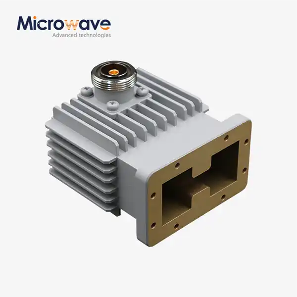 VIEW MOREHigh Power Waveguide to Coaxial Adapter
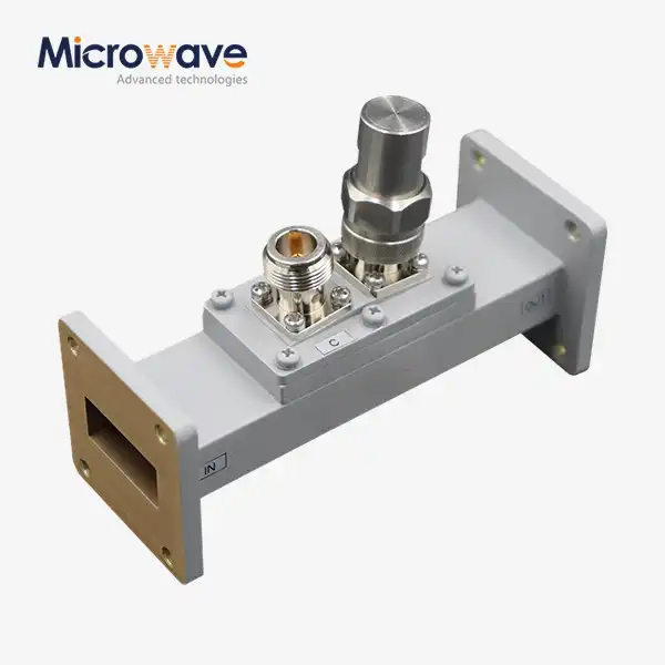 VIEW MOREWaveguide Loop Coupler
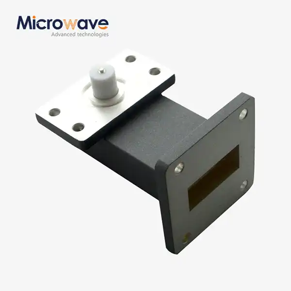 VIEW MORERight Angle Waveguide to Microstrip Adapter
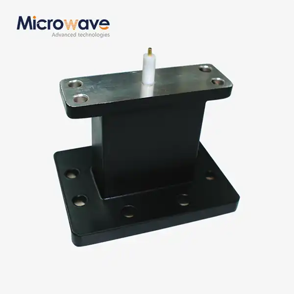 VIEW MOREEnd Launch Waveguide to Microstrip Adapter
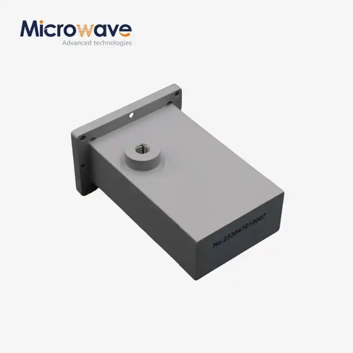 VIEW MOREWG Termination
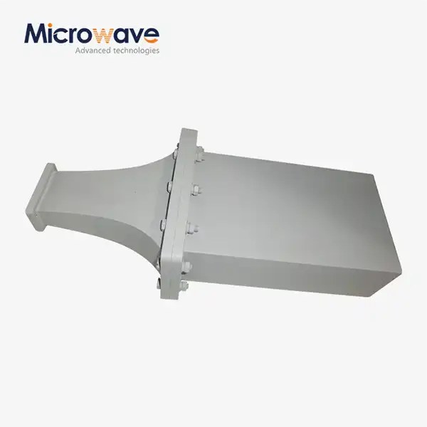 VIEW MOREDouble Ridge Waveguide Termination
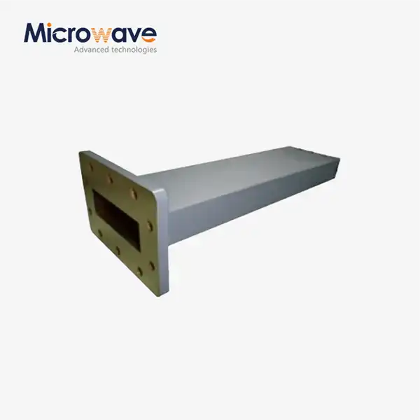 VIEW MOREWaveguide Unmatched Termination
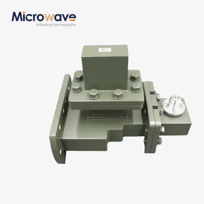 VIEW MOREE-Plane Tee
