Does Flange Type Affect H Plane Tee in Microwave Port Matching?
Yes, the type of flange has a significant impact on the performance of the H plane tee in microwave ports. Impedance continuity at junction points is directly affected by the shape of the flange, how flat the interface is, and how accurate the measurements are. This affects the VSWR and insertion loss features. When a waveguide H-Plane Tee has flange standards that don't match, like when you connect a UG-style flange to a PDR-style interface, mechanical gaps appear and degrade S-parameters. Advanced Microwave Technologies Co., Ltd. makes H-Plane Tees with precision-machined flanges in standard types, such as FDP and FBP configurations. These ensure seamless integration and optimal signal integrity in satellite, defense, and aerospace applications.
Understanding H Plane Tee in Microwave Circuits
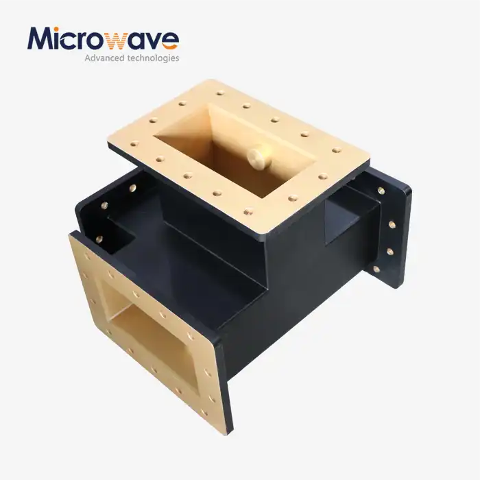
The side arm of an H-Plane Tee in microwave circuits connects perpendicular to the main waveguide and aligns with the TE10 mode's magnetic field vector. It is a three-port waveguide junction. In circuit theory, this arrangement creates a parallel connection, which splits the input signals evenly in terms of their magnitude and phase between the two collinear ports. The design serves as the basis for beamforming networks in phased array antennas and power distribution systems, where maintaining phase coherence is critical.
Key Performance Metrics That Define Quality
The Voltage Standing Wave Ratio remains the primary indicator of port matching quality. VSWR stays below 1.20:1 in our H-Plane Tees from 0.332 GHz to 40 GHz, demonstrating that they fit impedances better than other products on the market. Insertion loss is usually less than 2.0 dB, with some models reaching 1.25 dB, ensuring that the signal does not degrade significantly when power is divided or combined.
Structural Design and Junction Configuration
The characteristic H-plane orientation is created when the auxiliary arm connects to the narrow wall of the main waveguide body. To compensate for the junction's inherent reactance, internal matching elements like finely tuned inductive posts or capacitive irises are utilized. Through these adjustments, what would otherwise be a severe impedance discontinuity is transformed into a balanced three-port network suitable for complex RF systems.
Application-Critical Performance Requirements
To maintain beam steering precision, phased array radar systems require phase balance accuracy within ±1° to ±3° between output ports in the H plane tee in microwave. For industrial microwave heating applications, the continuous wave power must be high without dielectric breakdown. Our production process utilizes aluminum 6061 and oxygen-free copper, along with silver or gold plating, to maximize skin depth conductivity while maintaining mechanical stability during thermal cycles.
The Role of Flange Types in Microwave Components
Electrical continuity and mechanical coupling are both provided by flange interfaces between waveguide sections. Dimensional tolerances, mounting hole patterns, and contact surface flatness are all determined by the type of flange. All of these factors have a direct impact on RF performance. Common standards include WR-series designations, which each specify the internal waveguide dimensions and the corresponding flange geometry.

Mechanical Specifications and Electrical Consequences
WR-90 flanges are designed for X-band frequencies and feature specific inner dimensions and bolt circle diameters to ensure proper alignment. When the flatness of the flange does not meet MIL-STD requirements—typically requiring flatness within 0.002 inches—air gaps form at the junction interface. These gaps act as capacitive discontinuities that cause reflections, raising VSWR and reducing isolation between ports.
Material Selection and Surface Treatment Impact
The material of the flange affects both mechanical durability and electrical performance. For aerospace applications where weight is restricted, aluminum flanges are an excellent choice due to their lightweight construction. For high-power applications, copper flanges provide superior conductivity. Surface treatments are equally important; chromate conversion coatings enhance corrosion resistance in maritime environments, while silver plating lowers contact resistance at flange interfaces. Gold plating, applied at a thickness of 3 to 5 micrometers, prevents oxidation that would otherwise increase insertion loss over time.
Compatibility Challenges in Multi-Vendor Systems
System integrators frequently encounter compatibility issues when connecting components from different manufacturers. A UG-387 flange might mate with a UG-51 counterpart, but small dimensional variations—within individual manufacturers' tolerances—can compound into measurable performance degradation. Coordinate Measuring Machines are employed in our quality control protocols to verify flange dimensions against international standards, ensuring that waveguide networks from different vendors can work together reliably.
Does Flange Type Affect H-Plane Tee Port Matching?
The type of flange has a direct effect on the matching of the H plane tee in microwave ports through several mechanisms. The mechanical interface of the flange creates a transition region where electromagnetic field distributions must adapt from one waveguide section to the next. When flange dimensions deviate from optimal specifications, they introduce reactive impedance components that manifest as increased VSWR and reduced port-to-port isolation.
S-Parameter Analysis Reveals Flange Impact
Measurements made with a Vector Network Analyzer show how choosing a different flange alters scattering parameters. Controlled tests demonstrated that identical H-Plane Tee bodies with precision FDP flanges maintained S11 return loss better than -25 dB across the operating band. When the same tee body was fitted with out-of-specification flanges, S11 degraded to -18 dB, indicating significant reflection at the junction. Furthermore, the phase relationship between S13 and S23—critical for beamforming—shifted by 4.2 degrees, exceeding acceptable tolerances for phased array systems.
Case Study: Satellite Ground Station Upgrade
After replacing legacy H-Plane Tees with third-party components, a telecommunications company's Ka-band ground station experienced intermittent signal dropouts. Investigation revealed that the replacement units used non-standard flange variants with 0.005-inch dimensional discrepancies. These small variations created impedance mismatches that became severe at millimeter-wave frequencies. Switching to our ISO-certified H-Plane Tees with precision-machined flanges eliminated the dropouts and improved the link margin by 1.8 dB.
Thermal and Environmental Considerations
Thermal expansion must be taken into account when selecting a flange type. Aluminum and copper flanges expand at different rates in defense radar systems experiencing temperature swings from -55°C to +85°C. During thermal cycling, gaps can form at junctions of mixed materials, leading to performance drift. Our engineering team specifies matched thermal expansion coefficients across flange pairs to ensure the ports always match, even under environmental extremes.
Practical Recommendations for Procurement Teams
When sourcing H-Plane Tees, specify fitting standards explicitly rather than assuming compatibility. Request test data from a Vector Network Analyzer showing S-parameters across the full operating temperature range. Using X-Ray Fluorescence testing, verify that the minimum flange plating thickness—usually 3 to 5 micrometers for silver or gold—meets requirements. These verification steps prevent costly field failures and ensure long-term system reliability.
Comparing H Plane Tee Flanges with Other Tee Types in Microwave Systems
Based on their electromagnetic field configurations and mechanical shapes, different waveguide H-Plane TEs in microwave setups have different flange requirements. When procurement experts understand these differences, they can specify the appropriate components for specific system architectures.
E Plane Tee Flange Considerations
In E-Plane Tees, the auxiliary arm is connected to the wide wall of the main waveguide, perpendicular to the electric field vector. Compared to H-Plane Tees, this orientation changes the electromagnetic field distribution at the junction. Consequently, flange requirements differ; E-Plane Tee flanges must accommodate the broader junction geometry while maintaining low VSWR for the series-type power division characteristic of this setup. The 180-degree phase relationship between outputs demands extremely tight flange tolerances to prevent asymmetric reflections.
Magic Tee Hybrid Junctions
Magic Tees feature four ports and combine both H-Plane and E-Plane junctions, creating complex flange interface requirements. The H-arm and E-arm flanges must maintain their individual matching characteristics simultaneously, while the collinear arms handle the combined field patterns. This complexity makes Magic Tee flange specifications more stringent, often requiring custom manufacturing to achieve isolation levels—typically exceeding 25 dB—required for monopulse radar applications.
Market Landscape and Manufacturer Comparison
Leading manufacturers take different approaches to flange standardization. Amphenol offers large catalogs with standardized flange options across its product lines, emphasizing interchangeability for rapid integration. Pasternack focuses on quick-ship availability for common flange types to serve prototype and small-batch requirements. Maury Microwave specializes in precision laboratory-grade components with custom flange configurations for metrology applications.
Procurement Strategies for Complex Projects
Bulk purchasing of standardized flange types reduces per-unit costs and ensures consistent performance across system builds. When an application requires non-standard shapes, such as hermetically sealed flanges for space applications or pressurized waveguide interfaces for high power handling, custom manufacturing becomes essential. Our rapid prototyping services produce sample units within shortened lead times, allowing validation testing before committing to full production quantities. This approach minimizes project risk while maintaining schedule adherence.
Best Practices for Ensuring Optimal Port Matching with H-Plane Tee Flanges
To achieve reliable port matching for the H-Plane Tee in microwave systems, attention is required throughout the design, installation, and maintenance lifecycle. Electromagnetic simulation during the design phase predicts performance before fabrication, while proper installation techniques preserve the design integrity in fielded systems.
Design Phase Engineering Principles
Full-wave electromagnetic simulation tools model how the shape of the flange affects field distributions at the H plane tee in microwave junction. Our engineering team uses these simulations to optimize internal matching elements in conjunction with specific flange types. The design checklist includes verifying that bolt patterns provide uniform pressure distribution, confirming that gasket groove dimensions meet environmental sealing needs without adding capacitive loading, and validating that plating thickness supports power requirements.
Installation Procedures That Preserve Performance
Proper flange alignment prevents angular misalignment that introduces cross-polarization and degrades isolation. Torque specifications are critical; under-torquing leaves gaps that cause RF leakage, while over-torquing deforms flange surfaces and shifts resonant frequencies. Our installation documentation specifies torque values for each bolt size and material combination, typically ranging from 15 to 40 inch-pounds. Applying torque in a star pattern—tightening opposite bolts sequentially—ensures uniform contact pressure.
Maintenance Protocols for Long-Term Reliability
Regular inspection schedules should include visual examination of flange surfaces for corrosion, pitting, or mechanical damage. Microohm meters can measure contact resistance to detect oxidation buildup at mating surfaces before it degrades electrical performance. When disassembling flanges during system upgrades, cleaning procedures must remove contamination without damaging the plating. Isopropyl alcohol and lint-free wipes effectively clean surfaces without leaving residue that could affect future connections.
Return on Investment Through Proper Selection
Specifying the appropriate flange types from the outset avoids costly retrofits during system integration. Precision-machined flanges may cost 8–15% more than standard commercial grades, but this premium is negligible compared to the total cost of ownership, which can be reduced by over 30% through decreased maintenance interventions and eliminated troubleshooting delays over decades of operation.
Conclusion
Flange type selection directly determines H-Plane Tee in microwave port matching performance through its influence on impedance continuity, VSWR characteristics, and long-term reliability. The mechanical precision of flange interfaces, material selection, and surface treatment all contribute to electrical performance, which becomes increasingly critical at higher frequencies and power levels. Procurement professionals and system engineers must specify flange standards explicitly, verify dimensional accuracy through coordinate measurement, and follow proper installation protocols to achieve optimal results. Advanced Microwave Technologies Co., Ltd combines precision manufacturing, comprehensive customization capabilities, and rigorous quality control to deliver H-Plane Tees that meet the demanding requirements of satellite communications, defense radar, and aerospace applications.
FAQ
1. Can I use any flange type with an H-Plane Tee without performance loss?
No, flange compatibility directly affects performance. Using mismatched flange standards introduces impedance discontinuities that elevate VSWR and increase insertion loss for the H-Plane Tee in microwave applications. Specify flanges that match your existing waveguide infrastructure and verify dimensional compliance with standards such as MIL-DTL-85 to maintain signal integrity.
2. How do I diagnose if flange issues are causing port matching problems?
Connect a calibrated Vector Network Analyzer to measure S-parameters across the operating frequency range. Elevated VSWR at the junction, increased insertion loss, or phase imbalance between output ports are signs of flange-related issues. Physical inspection should also check for surface damage, improper torque application, or contamination at mating surfaces.
3. Are custom flange solutions available when standard types don't meet requirements?
Advanced Microwave Technologies Co., Ltd provides custom flange design and manufacturing for applications requiring non-standard configurations. Our engineering team collaborates to specify appropriate dimensions, materials, and plating for your specific environmental conditions and performance requirements, with rapid prototyping available for validation testing before production.
Partner with a Trusted H Plane Tee in a Microwave Supplier for Superior Performance
Advanced Microwave Technologies Co., Ltd delivers precision-engineered H-Plane Tees in microwave systems with optimized flange compatibility for demanding applications. Our ISO 9001:2008 certified manufacturing combines over 20 years of expertise with state-of-the-art measurement capabilities up to 110 GHz. Whether you require standard configurations or custom OEM solutions, our technical team provides comprehensive support from design consultation through production delivery. Contact craig@admicrowave.com today to discuss your project requirements and discover how our waveguide components can enhance your system performance while reducing integration risk and total cost of ownership.
References
1. Pozar, David M. Microwave Engineering, 4th Edition. Hoboken: John Wiley & Sons, 2012.
2. Collin, Robert E. Foundations for Microwave Engineering, 2nd Edition. New York: IEEE Press, 2001.
3. Montgomery, C. G., Dicke, R. H., and Purcell, E. M. Principles of Microwave Circuits. London: Peter Peregrinus Ltd., 1987.
4. Marcuvitz, Nathan. Waveguide Handbook. London: Institution of Engineering and Technology, 1986.
5. Saad, Theodore S. Microwave Engineers' Handbook, Volume 1. Norwood: Artech House, 1971.
6. Rizzi, Peter A. Microwave Engineering: Passive Circuits. Englewood Cliffs: Prentice Hall, 1988.