Coplanar Waveguide: Definition & Types
In the demanding world of high-frequency RF and microwave circuit design, signal integrity challenges can derail even the most carefully planned projects. Engineers working on 5G infrastructure, satellite communications, and advanced radar systems constantly battle signal loss, impedance mismatches, and integration complexities that threaten system performance. The cpw waveguide emerges as a powerful solution to these persistent pain points, offering a planar transmission line architecture that combines superior electromagnetic confinement with remarkable design flexibility. This comprehensive guide explores coplanar waveguide fundamentals, examines the various cpw waveguide types available today, and demonstrates how this transmission line technology addresses critical challenges in modern high-frequency applications.
Understanding CPW Waveguide Fundamentals
Coplanar waveguide represents a sophisticated planar transmission line structure where all conductors reside on the same plane of a dielectric substrate. Unlike conventional microstrip configurations that position the ground plane on the opposite substrate side, the cpw waveguide features a central signal-carrying conductor flanked by two parallel ground planes on the identical surface. This coplanar arrangement creates a unique electromagnetic field distribution that exists partly within the dielectric substrate and partly in the air above, establishing what engineers characterize as a quasi-TEM (transverse electromagnetic) propagation mode at lower frequencies, transitioning to higher-order modes as frequency increases.
The fundamental cpw waveguide geometry is defined by three critical dimensional parameters: the central conductor width, the gap spacing between the signal strip and adjacent ground planes, and the substrate thickness. These parameters work together to determine the transmission line's characteristic impedance, typically ranging from 30 to 150 ohms depending on application requirements. The electromagnetic energy concentration within the coplanar structure occurs primarily in the narrow gap regions between conductors, where electric field intensity reaches maximum values. This field distribution pattern provides excellent electromagnetic confinement while minimizing radiation losses that plague other planar transmission line configurations. Advanced Microwave Technologies Co., Ltd. leverages this fundamental cpw waveguide architecture to deliver high-performance transmission line solutions. Our designs optimize the conductor-to-ground spacing relationship to achieve precise impedance control while maintaining low signal attenuation across broad frequency ranges. The planar structure inherent to cpw waveguide configurations enables straightforward integration with other planar circuit components, including active devices, passive elements, and antenna structures. This integration capability proves invaluable in modern communication systems where circuit miniaturization and multi-function integration drive design requirements. The cpw waveguide's symmetric geometry also facilitates differential signal transmission when required, providing design engineers with versatile options for various system architectures.
Basic CPW Waveguide Structure and Operating Principles
The physical realization of cpw waveguide transmission lines begins with selecting appropriate substrate materials that provide stable dielectric properties across the intended operating frequency range. Common substrate choices include alumina ceramics for high-power applications, Rogers laminates for commercial RF systems, and various semiconductor substrates for monolithic microwave integrated circuit implementations. The central conductor and ground planes are typically fabricated using copper, gold, or aluminum metallization through photolithographic patterning processes that achieve dimensional tolerances measured in micrometers.
When electromagnetic energy propagates along a cpw waveguide, the electric field lines predominantly traverse the gaps between the signal conductor and ground planes, while magnetic field lines encircle the current-carrying conductors according to Ampere's law. This field configuration establishes the transmission line's characteristic behavior and determines how signals interact with the structure. The substrate's dielectric constant directly influences the effective permittivity experienced by propagating waves, which in turn affects phase velocity and wavelength. Engineers exploit this relationship to design cpw waveguide sections with specific electrical lengths required for impedance matching networks, filter structures, and other frequency-selective circuits. Advanced Microwave Technologies Co., Ltd. manufactures cpw waveguide products using precision aluminum construction with natural color anodizing finishes that provide excellent surface conductivity and corrosion resistance. Our ADM-20CPWST1 model operates from DC to 20 GHz with voltage standing wave ratio values below 1.30 across the entire frequency range, demonstrating superior impedance matching characteristics. The insertion loss remains below 1.5 dB, ensuring efficient signal transmission with minimal power dissipation. These performance specifications result from careful attention to conductor geometry optimization, material selection, and manufacturing process control that maintains tight dimensional tolerances throughout production.
Types of Coplanar Waveguide Configurations
The versatility of cpw waveguide technology manifests through several distinct structural variations, each optimized for specific application requirements and performance characteristics. Understanding these different cpw waveguide types enables designers to select the most appropriate configuration for their particular system needs, balancing factors such as circuit density, thermal management, frequency response, and manufacturing complexity.
Conventional CPW Waveguide
The conventional or classic cpw waveguide represents the foundational configuration featuring a center conductor strip positioned between two semi-infinite ground planes that extend laterally to considerable distances relative to the signal strip width. This idealized structure assumes ground planes of infinite extent, though practical implementations employ finite ground widths that approximate infinite plane behavior when the ground conductor width exceeds approximately three times the sum of the signal strip width plus twice the gap spacing. The conventional cpw waveguide provides excellent electromagnetic field confinement and predictable characteristic impedance values that can be calculated using established analytical formulas derived from conformal mapping techniques. Engineers favor conventional cpw waveguide designs for applications requiring maximum isolation between adjacent transmission lines and superior electromagnetic compatibility characteristics. The broad ground planes provide effective shielding that minimizes crosstalk between parallel cpw waveguide routes on densely populated circuit boards. This shielding capability proves particularly valuable in multi-channel receiver systems, phased array antenna feed networks, and other applications where channel-to-channel isolation directly impacts system performance. Advanced Microwave Technologies Co., Ltd. implements conventional cpw waveguide architectures in our standard product offerings, optimizing ground plane dimensions to achieve the ideal balance between electromagnetic performance and circuit real estate utilization.
Conductor-Backed CPW Waveguide
Conductor-backed coplanar waveguide, frequently abbreviated as CBCPW or alternatively termed coplanar waveguide with ground, introduces a continuous metal ground plane covering the entire back surface of the dielectric substrate opposite the coplanar conductors. This additional ground plane functions as a third return current path that fundamentally alters the electromagnetic field distribution compared to conventional cpw waveguide structures. The conductor backing modifies the effective dielectric constant experienced by propagating waves and typically increases the characteristic impedance for given geometric dimensions. More importantly, the backside ground plane provides excellent heat dissipation pathways for circuits handling significant RF power levels and establishes a well-defined reference plane that simplifies circuit grounding schemes. The conductor-backed cpw waveguide configuration offers distinct advantages in high-power applications where thermal management concerns drive design decisions. Active circuit elements such as power amplifiers, frequency multipliers, and high-power switches generate substantial heat that must be efficiently removed to maintain reliable operation and prevent device degradation. The backside ground plane in CBCPW structures provides a direct thermal conduction path to external heat sinks, effectively spreading heat away from localized hot spots. Advanced Microwave Technologies Co., Ltd. recognizes these thermal management benefits and incorporates conductor-backed cpw waveguide designs in applications requiring enhanced heat dissipation capabilities. Our aluminum construction with optimized thermal interface properties ensures stable operation even under continuous high-power transmission conditions.
Finite Ground CPW Waveguide
Finite ground cpw waveguide addresses practical manufacturing and circuit layout constraints by implementing ground planes of limited lateral extent rather than the semi-infinite ground planes assumed in theoretical analyses. This configuration more accurately represents real-world cpw waveguide implementations where circuit board dimensions, component placement requirements, and cost considerations necessitate constraining ground plane widths. When properly dimensioned, finite ground cpw waveguide exhibits electrical characteristics nearly identical to conventional cpw waveguide with infinite ground planes, provided the ground conductor width exceeds specific minimum values relative to the center conductor and gap dimensions. Design guidelines for finite ground cpw waveguide recommend ground plane widths of at least three times the center strip width to maintain predictable performance characteristics. As ground plane width decreases below this threshold, the electromagnetic fields begin interacting with structures beyond the ground plane boundaries, introducing mode conversion effects and altering the effective dielectric constant and characteristic impedance values. Advanced Microwave Technologies Co., Ltd. applies rigorous electromagnetic simulation techniques to verify finite ground cpw waveguide designs, ensuring that ground plane dimensioning maintains required performance specifications while optimizing circuit layout efficiency. Our design team balances electromagnetic performance requirements against practical circuit board utilization to deliver cost-effective solutions that meet stringent electrical specifications.
Grounded CPW Waveguide
Grounded coplanar waveguide extends the conductor-backed cpw waveguide concept by adding vertical electrical connections, typically implemented as plated through-hole vias, that join the coplanar ground planes on the circuit surface to the backside ground plane. These grounding vias establish multiple return current paths and suppress unwanted parallel-plate waveguide modes that can propagate between the coplanar ground planes and the backside conductor in conductor-backed structures lacking via connections. The grounded cpw waveguide configuration provides the most robust electromagnetic field confinement among cpw waveguide variants, minimizing radiation losses and preventing spurious mode excitation that degrades transmission line performance at higher frequencies. The strategic placement of grounding vias along cpw waveguide lengths requires careful consideration of via spacing relative to operating wavelength. Electromagnetic theory suggests via separation should not exceed one-quarter wavelength at the highest operating frequency to effectively suppress parallel-plate modes without introducing significant impedance discontinuities. Advanced Microwave Technologies Co., Ltd. optimizes grounded cpw waveguide implementations for applications spanning millimeter-wave frequencies where mode suppression becomes critical for maintaining signal integrity. Our manufacturing capabilities include precision via drilling and plating processes that achieve the close via spacing required for effective mode suppression while maintaining the tight dimensional tolerances necessary for controlled impedance transmission lines operating into the millimeter-wave spectrum.
Key Performance Characteristics of CPW Waveguide
The cpw waveguide architecture delivers several distinctive performance attributes that position this transmission line technology as a preferred choice for demanding high-frequency applications. Understanding these characteristic features enables engineers to leverage cpw waveguide capabilities effectively while appreciating the trade-offs inherent in different transmission line selections.
Low Transmission Loss Performance
Signal attenuation represents one of the most critical performance parameters for any transmission line system, directly impacting achievable communication range, receiver sensitivity requirements, and overall system power efficiency. The cpw waveguide structure inherently provides low-loss signal transmission through several complementary mechanisms. First, the planar conductor configuration with optimized current distribution minimizes resistive losses associated with finite metal conductivity. Second, the electromagnetic field concentration within narrow gap regions reduces dielectric losses by limiting field penetration into lossy substrate materials. Third, the quasi-TEM field structure minimizes dispersion effects that can cause signal distortion over long transmission line lengths. Advanced Microwave Technologies Co., Ltd. achieves exceptionally low insertion loss in our cpw waveguide products through meticulous attention to conductor surface finish and geometric precision. Our high-quality aluminum construction with natural color anodizing provides excellent surface conductivity while the optimized conductor shapes reduce current crowding effects that increase resistive losses. The careful selection of substrate materials with low loss tangent values further minimizes dielectric loss contributions. Our ADM-20CPWST1 model maintains insertion loss below 1.5 dB across its DC to 20 GHz operating range, demonstrating the superior transmission efficiency achievable with properly designed cpw waveguide structures. This low-loss performance translates directly into improved system performance, enabling longer transmission distances, reduced transmitter power requirements, and enhanced receiver sensitivity.
Precise Impedance Control Capabilities
Characteristic impedance matching throughout signal paths determines the efficiency of power transfer between circuit elements and minimizes signal reflections that degrade system performance. The cpw waveguide geometry provides exceptionally precise impedance control through independent adjustment of the center conductor width and gap spacing parameters. This design flexibility enables engineers to realize specific impedance values required for optimal system matching while accommodating manufacturing tolerances and material property variations. The mathematical relationship between cpw waveguide dimensions and characteristic impedance follows well-established formulas that facilitate accurate impedance synthesis during initial design phases. Manufacturing precision directly impacts achieved impedance accuracy in practical cpw waveguide implementations. Dimensional variations in conductor width or gap spacing translate into impedance deviations that can cause impedance mismatches and associated signal reflections. Advanced Microwave Technologies Co., Ltd. employs state-of-the-art manufacturing technology that maintains tight dimensional tolerances throughout production, ensuring that fabricated cpw waveguide products exhibit impedance values within narrow tolerances of design targets. Our quality control procedures include impedance verification measurements on representative samples from each production lot, validating that impedance specifications are consistently met. This rigorous approach to impedance control enables our customers to achieve excellent VSWR performance, with values below 1.30 across wide frequency ranges, indicating minimal impedance mismatch and efficient power transfer throughout their systems.
Design Flexibility and Customization Options
The planar nature of cpw waveguide transmission lines provides remarkable design flexibility that accommodates diverse application requirements and system architectures. Unlike rigid coaxial transmission lines or three-dimensional waveguide structures, cpw waveguide circuits can be routed along curved paths, incorporate arbitrary bends and transitions, and integrate seamlessly with planar circuit components through simple conductor patterning processes. This geometric adaptability enables compact circuit layouts that maximize functional density while maintaining controlled impedance characteristics throughout complex routing paths. Engineers can customize cpw waveguide dimensions, substrate materials, and conductor metallization to optimize performance for specific frequency ranges, power handling requirements, and environmental conditions. Advanced Microwave Technologies Co., Ltd. offers comprehensive customization services for cpw waveguide products, tailoring designs to meet unique customer specifications. Our experienced engineering team works closely with clients to understand their application requirements, operating conditions, and performance objectives. We leverage advanced electromagnetic simulation tools to optimize cpw waveguide geometries before committing to fabrication, ensuring that custom designs meet all electrical specifications while maintaining manufacturability. The customizable nature of cpw waveguide technology allows us to address diverse applications including 5G communication systems operating in millimeter-wave bands, automotive radar sensors requiring compact integration, and satellite communication equipment demanding lightweight, reliable performance in harsh space environments. Our flexible manufacturing processes accommodate both prototype quantities for research and development activities and volume production for commercial deployment.
Excellent Heat Dissipation Properties
Thermal management considerations become increasingly critical as RF and microwave systems handle higher power levels and operate in thermally challenging environments. The cpw waveguide structure provides inherent thermal advantages through the adjacent ground plane conductors that function as efficient heat spreaders. These ground planes conduct heat away from the signal-carrying center conductor, distributing thermal energy over larger surface areas that facilitate convective and radiative heat dissipation to the surrounding environment. When combined with conductor-backed configurations, cpw waveguide implementations establish direct thermal conduction paths to external heat sinks, further enhancing heat removal capabilities. Advanced Microwave Technologies Co., Ltd. recognizes that reliable high-power operation demands effective thermal management solutions. Our cpw waveguide products incorporate design features that optimize heat dissipation while maintaining electrical performance specifications. The aluminum construction material provides excellent thermal conductivity that efficiently spreads heat throughout the waveguide structure. The natural color anodizing finish not only protects the aluminum surface from corrosion but also enhances thermal emissivity, improving radiative heat dissipation. This combination of design optimization and material selection ensures stable performance during continuous high-power transmission, enhancing system reliability and extending operational lifetime. Applications such as high-power radar transmitters, satellite communication earth stations, and cellular base station power amplifiers benefit significantly from these superior thermal management characteristics inherent to cpw waveguide architectures.
CPW Waveguide Applications Across Industries
The versatile performance characteristics of cpw waveguide technology have established this transmission line architecture as an essential building block across numerous high-frequency application domains. Understanding how cpw waveguide solutions address specific industry challenges demonstrates the practical value this technology delivers to modern communication, sensing, and electronic warfare systems.
5G and Advanced Wireless Communication Systems
The global deployment of fifth-generation wireless networks relies heavily on millimeter-wave frequency bands that provide the wide bandwidth necessary for multi-gigabit data transmission rates. Operating in frequency ranges from 24 GHz extending to 40 GHz and beyond, these 5G systems demand transmission line solutions that maintain low loss and precise impedance control across broad frequency spans. The cpw waveguide architecture meets these stringent requirements through its planar structure that integrates efficiently with millimeter-wave antennas, RF front-end components, and baseband processing circuits. The low-loss transmission characteristics of properly designed cpw waveguide implementations preserve signal power throughout the RF chain, maximizing system efficiency and extending coverage ranges. Base station deployments for 5G networks incorporate cpw waveguide transmission lines to route signals between antenna arrays and transceiver electronics while maintaining signal integrity. The compact planar form factor enables dense circuit layouts that accommodate the numerous parallel RF chains required for massive MIMO antenna systems that spatially multiplex signals to achieve unprecedented spectral efficiency. Advanced Microwave Technologies Co., Ltd. provides cpw waveguide solutions optimized for 5G infrastructure applications, supporting the frequency bands allocated for commercial 5G deployment worldwide. Our products deliver the consistent performance required for reliable network operation while accommodating the thermal management challenges associated with high-power transmission. As wireless networks continue evolving toward sixth-generation technologies operating at even higher frequencies, cpw waveguide architectures will remain fundamental enabling technologies for next-generation communication systems.
Radar and Remote Sensing Systems
Radar systems spanning applications from automotive collision avoidance to weather monitoring rely on cpw waveguide transmission lines to route high-frequency signals between transmitter sources, receiver front-ends, and antenna structures. The precise impedance control inherent to cpw waveguide designs ensures minimal signal reflections that would otherwise introduce unwanted phase errors and amplitude variations degrading radar detection accuracy. Automotive radar systems operating at 77 GHz for adaptive cruise control and collision warning applications particularly benefit from cpw waveguide integration capabilities that enable compact, cost-effective implementations suitable for mass production. The design flexibility of cpw waveguide technology allows customization of transmission line characteristics to optimize radar beam-shaping performance and target resolution. Weather monitoring radar installations utilize cpw waveguide components in phased array antenna feed networks that electronically steer radar beams to scan atmospheric conditions across wide coverage areas. The low-loss transmission performance of cpw waveguide implementations preserves the precious milliwatts of radar echo returns received from distant precipitation targets, enabling detection of weather phenomena at maximum ranges. Advanced Microwave Technologies Co., Ltd. supports radar system developers with cpw waveguide products engineered for demanding environmental conditions encountered in operational radar deployments. Our manufacturing quality standards ensure consistent performance across production quantities, while our technical support team assists customers with application-specific design optimization. The combination of superior electrical performance, mechanical ruggedness, and design flexibility positions cpw waveguide technology as an optimal choice for current and future radar sensing applications.
Satellite and Space Communication Systems
The harsh operating environment of space applications demands transmission line solutions that deliver reliable performance across extreme temperature ranges while minimizing mass and maintaining mechanical stability under launch acceleration loads. The cpw waveguide structure addresses these challenging requirements through its planar, lightweight design that eliminates the need for bulky coaxial connectors or heavy waveguide assemblies traditionally employed in satellite payloads. The inherent robustness of planar cpw waveguide fabrication provides mechanical stability that withstands thermal cycling between sunlit and shadow periods in orbital operation. The excellent heat dissipation properties of cpw waveguide configurations facilitate passive thermal management approaches that maintain stable operating temperatures without active cooling systems. Modern satellite communication systems handling high data rate downlink and uplink signals benefit from the low-loss, wideband transmission characteristics of cpw waveguide technology. The efficient power transfer enabled by precise impedance control reduces overall payload power consumption, a critical consideration for satellites operating with limited solar panel generated power. Advanced Microwave Technologies Co., Ltd. manufactures cpw waveguide products that meet the stringent quality and reliability standards required for space applications. Our testing procedures validate performance across the temperature extremes encountered in orbital environments, while material selection ensures compatibility with vacuum outgassing requirements that prevent spacecraft contamination. As commercial and military satellite systems continue advancing toward higher frequencies and increased capacity, cpw waveguide implementations will play increasingly important roles in enabling next-generation space communication architectures.
Microwave and Millimeter-Wave Integrated Circuits
The integration of cpw waveguide transmission lines with active and passive components in monolithic microwave integrated circuits and millimeter-wave integrated circuits represents a major application domain leveraging the planar nature of cpw waveguide technology. The coplanar conductor arrangement simplifies fabrication processes compared to alternative transmission line structures requiring backside processing or multi-layer metallization schemes. This fabrication simplicity translates into improved manufacturing yields and reduced production costs for complex circuits incorporating numerous transmission line sections, impedance matching networks, and component interconnections. The cpw waveguide structure seamlessly integrates with transistor and diode mounting pads, enabling direct connection of active devices without requiring via connections to ground planes on different metal layers. Chip-level microwave circuits for applications such as power amplifiers, frequency mixers, voltage-controlled oscillators, and phase shifters routinely employ cpw waveguide transmission lines throughout their signal routing architectures. The precise impedance control capabilities of cpw waveguide designs enable optimization of impedance matching networks that maximize power transfer between circuit stages, directly improving overall system performance metrics such as output power, efficiency, and noise figure. Advanced Microwave Technologies Co., Ltd. supports integrated circuit developers through custom cpw waveguide component design services and specialized measurement capabilities. Our 24-meter microwave darkroom equipped with advanced measurement systems operating to 110 GHz enables comprehensive characterization of cpw waveguide performance across millimeter-wave frequency ranges. This measurement capability provides customers with detailed validation data supporting their circuit design optimization efforts.
Conclusion
Coplanar waveguide technology represents a mature yet continually evolving transmission line architecture that addresses critical challenges in modern high-frequency system design through its unique combination of low-loss performance, precise impedance control, planar integration capabilities, and excellent thermal management properties.
Cooperate with Advanced Microwave Technologies Co., Ltd.
Advanced Microwave Technologies Co., Ltd. stands as a leading China cpw waveguide manufacturer with over 20 years of expertise delivering high-quality cpw waveguide solutions to global markets. As a trusted China cpw waveguide supplier and China cpw waveguide factory, we offer competitive cpw waveguide wholesale pricing alongside professional OEM services tailored to your specifications. Our ISO 9001:2015, ISO 14001:2015, and ISO 45001:2018 certifications demonstrate our commitment to quality, environmental stewardship, and workplace safety. Whether you need cpw waveguide for sale for immediate projects or seek a reliable China cpw waveguide supplier for ongoing requirements, our experienced team provides comprehensive support from initial design through production and delivery. Our state-of-the-art 24m Microwave Darkroom with measurement capabilities to 110 GHz ensures rigorous testing and validation of every high quality cpw waveguide product. Contact us at craig@admicrowave.com to discuss how our cpw waveguide solutions, competitive cpw waveguide price, and fast delivery capabilities can support your next high-frequency project. Partner with us for cutting-edge transmission line technology backed by decades of microwave engineering excellence.
References
1. Wen, C. P. (1969). Coplanar Waveguide: A Surface Strip Transmission Line Suitable for Nonreciprocal Gyromagnetic Device Applications. IEEE Transactions on Microwave Theory and Techniques, Vol. MTT-17, No. 12, pp. 1087-1090.
2. Ghione, G., and Naldi, C. U. (1987). Coplanar Waveguides for MMIC Applications: Effect of Upper Shielding, Conductor Backing, Finite-Extent Ground Planes, and Line-to-Line Coupling. IEEE Transactions on Microwave Theory and Techniques, Vol. MTT-35, No. 3, pp. 260-267.
3. Simons, R. N. (2001). Coplanar Waveguide Circuits, Components, and Systems. John Wiley & Sons, New York.
4. Collin, R. E. (1992). Foundations for Microwave Engineering, Second Edition. McGraw-Hill, Inc., New York.
YOU MAY LIKE
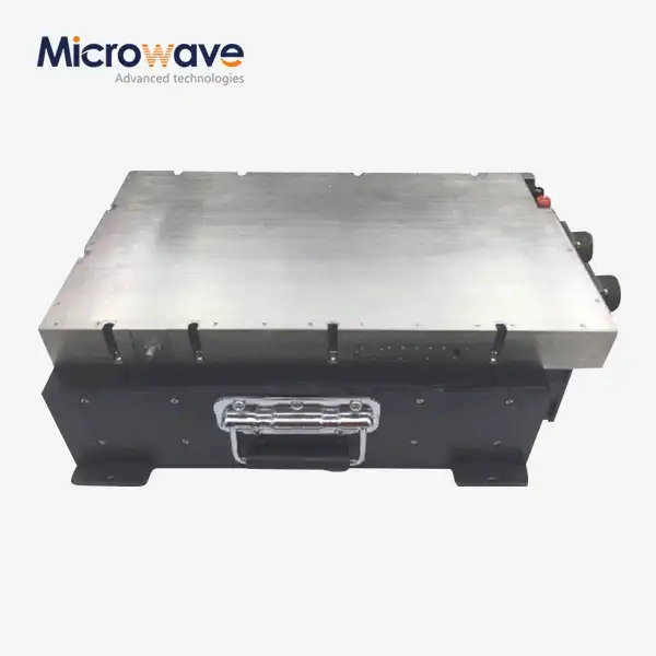 VIEW MOREAc Power Amplifier
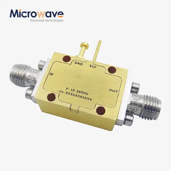 VIEW MOREVoltage Controlled Phase Shifter
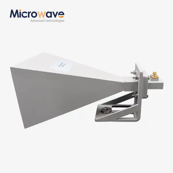 VIEW MOREStandard Horn Antenna
 VIEW MOREConical Horn Lens Antenna
 VIEW MOREPoint Focusing Horn Lens Antenna
 VIEW MOREFeed Fired Lens Antenna
 VIEW MORECorrugated Horn and Multimode Horn Antenna
 VIEW MOREMini Wideband Double-ridged Horn Antenna


