What is the difference between a fixed and variable attenuator?
In high-frequency signal management scenarios, engineers consistently face a critical challenge: maintaining precise control over signal strength without introducing distortion or compromising system integrity. Whether you're calibrating a satellite ground station, optimizing radar performance, or conducting advanced microwave testing, selecting the appropriate attenuator type directly impacts measurement accuracy, system reliability, and overall operational efficiency. The fundamental distinction between fixed and variable attenuators lies in their adjustability capabilities, but understanding the nuanced differences in design architecture, application scenarios, and performance characteristics is essential for making informed procurement decisions. A Waveguide Fixed Attenuator provides predetermined, unchangeable attenuation values ideal for permanent installations requiring consistent signal reduction, while variable attenuators offer dynamic control for applications demanding real-time adjustments across varying operational conditions.
Understanding the Core Differences Between Fixed and Variable Waveguide Attenuators
The primary distinction between these two attenuator categories centers on their ability to modify attenuation levels during operation. Fixed attenuators are precision-engineered components manufactured with predetermined attenuation values that remain constant throughout their operational lifetime. These devices typically come in standard attenuation ratings such as 3dB, 6dB, 10dB, 20dB, and 30dB, providing consistent and reliable signal reduction without requiring user intervention or adjustment mechanisms. The Waveguide Fixed Attenuator employs carefully calculated resistive networks integrated into waveguide structures, ensuring minimal reflection and maximum power handling capacity across specified frequency ranges. Manufacturing processes involve precision machining and material selection to achieve tight tolerances, resulting in components with exceptional stability even under temperature variations and mechanical stress.
Variable attenuators, conversely, incorporate adjustable mechanisms allowing operators to modify attenuation levels according to real-time system requirements. These sophisticated devices may feature manual control interfaces such as rotary knobs or digital input systems enabling programmatic adjustment through computer control or voltage regulation. The adjustment range typically extends from 0dB to 40dB or higher, with resolution capabilities varying based on the specific design architecture. Variable attenuators utilize advanced technologies including PIN diodes, field-effect transistors, or mechanical vane systems that physically alter the signal path characteristics within the waveguide structure. This adaptability makes them indispensable for applications requiring dynamic signal management, including automated test equipment, research laboratories, and adaptive communication systems where signal conditions fluctuate continuously. The engineering complexity differs substantially between these attenuator types. Waveguide Fixed Attenuators feature simplified construction with fewer components, resulting in enhanced reliability, lower insertion loss, and superior power handling capabilities. Their passive design eliminates the need for control circuitry or power supplies, reducing potential failure points and maintenance requirements. Variable attenuators necessarily incorporate more complex mechanical or electronic control systems, introducing additional components that require periodic calibration and maintenance. However, this increased complexity delivers operational flexibility that justifies the trade-off in applications where adaptability outweighs the benefits of simplicity.
Design Architecture and Construction Methodologies
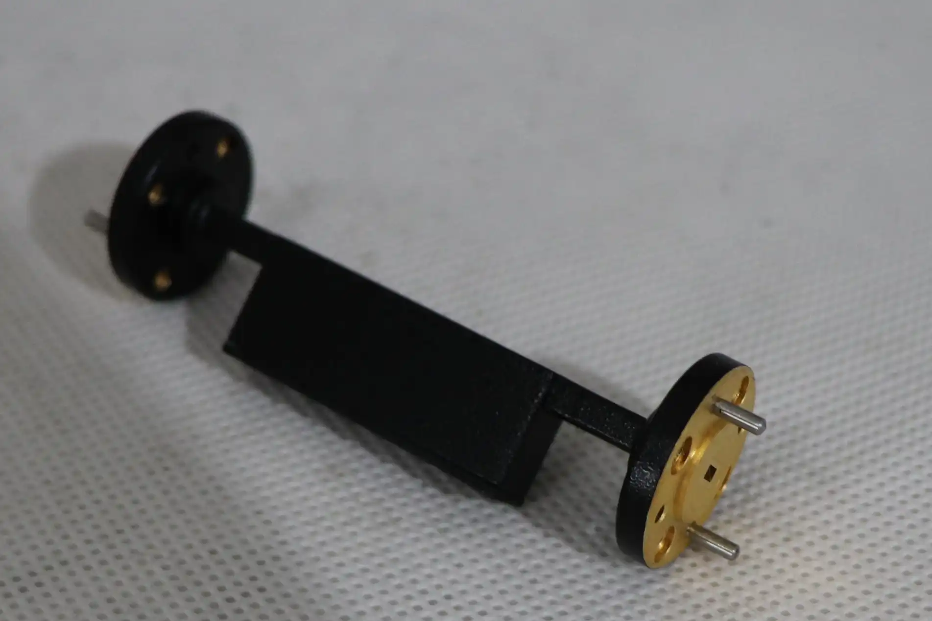
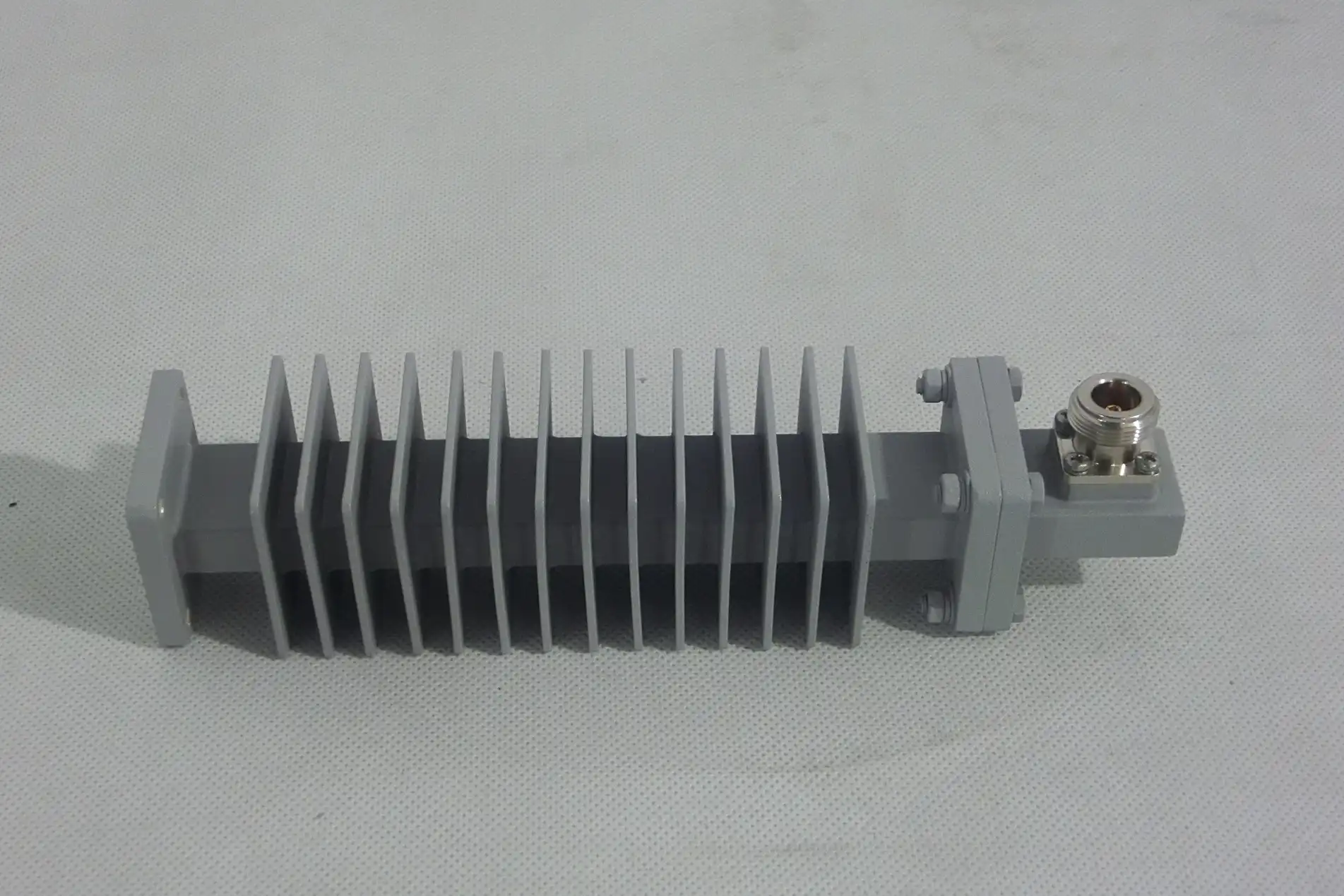
The internal construction of Waveguide Fixed Attenuators typically employs one of several proven resistive element configurations. The most common approach involves precision resistive films or cards positioned within the waveguide channel at calculated angles and positions to achieve the desired attenuation value. These resistive elements are manufactured from materials exhibiting stable electrical properties across wide temperature ranges and frequency spectrums, ensuring consistent performance throughout the device's operational life. Advanced manufacturing techniques including thin-film deposition, laser trimming, and precision assembly guarantee that each unit meets stringent specifications for attenuation accuracy, typically within ±0.5dB of the nominal value. The waveguide housing itself is machined from high-conductivity materials such as aluminum or copper alloys, with internal surfaces often plated with gold or silver to minimize losses and prevent oxidation. Flange connections conform to industry-standard specifications, ensuring compatibility with existing waveguide systems while maintaining excellent electrical contact and mechanical stability. For high-power applications, thermal management considerations become critical, with some Waveguide Fixed Attenuator designs incorporating enhanced heat dissipation features such as extended housing sections or integrated cooling fins to prevent thermal degradation of the resistive elements. Variable attenuator construction requires more sophisticated engineering to accommodate the adjustment mechanism while maintaining electrical performance. Mechanical variable attenuators commonly employ a resistive vane or card that moves within the waveguide channel, with the depth of penetration determining the attenuation level. Precision calibrated scales or digital readouts provide operators with accurate indication of the current attenuation setting. Electronic variable attenuators utilize semiconductor devices whose electrical characteristics change in response to applied control voltages, enabling remote adjustment and integration with automated systems. Both approaches demand careful attention to mechanical precision, with tolerances measured in micrometers to ensure repeatable performance across the adjustment range.
Performance Characteristics and Technical Specifications
When evaluating attenuator performance, several key specifications determine suitability for specific applications. For Waveguide Fixed Attenuators, attenuation accuracy represents a critical parameter, typically specified as the maximum deviation from the nominal value across the rated frequency range. High-quality fixed attenuators maintain accuracy within ±0.3dB to ±0.5dB, with premium units achieving even tighter tolerances. Frequency response flatness indicates how consistently the device maintains its attenuation value across the specified bandwidth, with superior designs exhibiting less than ±0.3dB variation across multi-gigahertz ranges extending from 0.5 GHz to 110 GHz. Voltage Standing Wave Ratio (VSWR) quantifies the impedance matching quality, with lower values indicating better performance. Precision Waveguide Fixed Attenuators typically achieve VSWR values of 1.15:1 or better, minimizing signal reflections that could compromise measurement accuracy or system stability. Power handling capacity varies significantly based on design and construction, with standard attenuators accommodating continuous wave power levels from several watts to hundreds of watts, while specialized high-power units support kilowatt-level applications through enhanced thermal management and robust resistive element designs. Variable attenuators introduce additional performance considerations related to their adjustment mechanisms. Attenuation range defines the span between minimum and maximum attenuation values, typically extending from 0dB or 1dB up to 40dB, 60dB, or even 90dB in specialized designs. Resolution or step size determines the smallest attenuation increment achievable, ranging from coarse steps of 1dB in mechanical designs to fine increments of 0.1dB or less in precision electronic variants. Repeatability specifies how consistently the attenuator returns to a given setting after cycling through different attenuation values, with high-quality units maintaining repeatability within ±0.2dB.
Practical Applications and Industry-Specific Requirements
The selection between fixed and variable attenuators depends heavily on application-specific requirements and operational scenarios. Waveguide Fixed Attenuators excel in permanent installations where signal levels remain consistent and predetermined attenuation values adequately serve system needs. Satellite communication ground stations frequently employ fixed attenuators to establish proper signal levels between high-power amplifiers and sensitive receiver components, protecting downstream equipment from excessive power while maintaining optimal signal-to-noise ratios. The unchanging nature of fixed attenuators provides long-term stability, eliminating concerns about accidental adjustment or drift that could degrade system performance over time. Radar systems utilize Waveguide Fixed Attenuators for calibration purposes and to establish reference power levels during testing and maintenance procedures. Air traffic control radar installations, weather monitoring systems, and military surveillance platforms all benefit from the reliability and precision of fixed attenuation. In these critical applications, the simplified design of fixed attenuators contributes to system reliability, as fewer components mean reduced failure probability and extended maintenance intervals. The ability to specify exact attenuation values during system design allows engineers to optimize signal chain performance, ensuring that each component operates within its optimal input power range. Variable attenuators find their primary application domain in testing, measurement, and research environments where signal level flexibility is paramount. Automated test equipment in telecommunications laboratories relies on variable attenuators to simulate various signal strength conditions, enabling comprehensive evaluation of receiver sensitivity, dynamic range, and interference rejection capabilities. Research institutions conducting advanced microwave experiments require the ability to precisely adjust signal levels during parameter optimization studies, making variable attenuators indispensable tools. The remote control capabilities of electronic variable attenuators facilitate integration with computerized test systems, enabling programmatic adjustment of attenuation values during automated test sequences.
Satellite Communication Systems and Ground Station Integration
Satellite ground stations represent one of the most demanding application environments for microwave components, requiring exceptional performance characteristics across multiple parameters. In uplink transmission chains, Waveguide Fixed Attenuators protect high-power amplifiers from excessive drive levels while ensuring proper signal strength at the antenna feed point. The stable performance of fixed attenuators maintains consistent link budgets, critical for reliable data transmission to orbiting satellites operating at distances spanning thousands to millions of kilometers. Downlink receive chains similarly benefit from fixed attenuation to establish appropriate signal levels for low-noise amplifiers and frequency conversion stages. Advanced ground station configurations may incorporate both fixed and variable attenuators to address different operational requirements. Fixed attenuators provide baseline signal conditioning in the main transmission and reception paths, while variable attenuators enable operators to compensate for atmospheric conditions, adjust for different satellite transponder characteristics, or conduct diagnostic testing without disrupting primary communication links. The frequency coverage extending from L-band through Ka-band and beyond demands attenuators capable of maintaining performance across octave-spanning bandwidths, with Waveguide Fixed Attenuators supporting frequencies up to 110 GHz in specialized millimeter-wave applications.
Defense and Aerospace Applications
Military radar systems, electronic warfare platforms, and aerospace communication equipment impose stringent requirements on all microwave components, including attenuators. The harsh operational environments characteristic of defense applications demand robust construction capable of withstanding shock, vibration, temperature extremes, and prolonged exposure to demanding conditions. Waveguide Fixed Attenuators designed for military specifications incorporate ruggedized housing construction, hermetic sealing to prevent contamination, and materials selected for thermal stability across temperature ranges extending from -55°C to +125°C or beyond. Phased array radar systems utilize networks of fixed attenuators to establish precise amplitude distributions across antenna elements, enabling optimal beam shaping and sidelobe control. The stability and repeatability of Waveguide Fixed Attenuators ensure consistent radar performance throughout the operational lifetime of the platform, whether deployed on naval vessels, aircraft, ground-based installations, or unmanned aerial vehicles. Surveillance and targeting systems benefit from the low insertion loss and excellent power handling characteristics that minimize signal degradation while maintaining operator safety through reliable power dissipation.
Selecting the Optimal Attenuator for Your Application
Choosing between fixed and variable attenuators requires careful analysis of system requirements, operational scenarios, and budget constraints. Engineers must evaluate several critical factors to ensure optimal component selection. First, determine whether your application requires adjustment capability during operation or if predetermined attenuation values adequately serve system needs. If signal levels remain constant and system design parameters are well-defined, Waveguide Fixed Attenuators typically provide the most cost-effective solution with superior reliability and simplified integration. Consider the frequency range your system must cover, ensuring that selected attenuators provide adequate performance across the entire bandwidth. Waveguide technology naturally constrains each attenuator design to specific frequency bands determined by waveguide dimensions, with common bands including X-band (8-12 GHz), Ku-band (12-18 GHz), K-band (18-27 GHz), Ka-band (27-40 GHz), and V-band (40-75 GHz), extending to W-band (75-110 GHz) for millimeter-wave applications. The Waveguide Fixed Attenuator must maintain specified performance characteristics throughout the operational bandwidth, with attenuation accuracy, VSWR, and insertion loss remaining within acceptable limits. Power handling requirements significantly influence attenuator selection, particularly in high-power transmission systems. Standard Waveguide Fixed Attenuators typically accommodate continuous wave power levels from 5 watts to 50 watts, depending on attenuation value and frequency band. High-power variants extend this capability to hundreds of watts or even kilowatt levels through enhanced thermal design, larger housing dimensions, and specialized resistive element construction. Calculate the maximum expected power level at the attenuator location, including appropriate safety margins to account for system transients and operational contingencies.
Quality Assurance and Certification Considerations
When sourcing Waveguide Fixed Attenuators from manufacturers, verify that production processes comply with relevant quality standards and environmental regulations. ISO 9001:2015 certification demonstrates that the manufacturer maintains comprehensive quality management systems covering design, production, and customer service processes. This certification provides assurance that each attenuator undergoes rigorous testing and inspection before shipment, with documented traceability for critical parameters. ISO 14001:2015 certification indicates environmental responsibility throughout manufacturing operations, ensuring that production processes minimize ecological impact through proper waste management, energy conservation, and emissions reduction. For applications in environments where worker safety is paramount, manufacturers holding ISO 45001:2018 certification demonstrate commitment to occupational health and safety management. This becomes particularly relevant when procuring components for large-scale installation projects or ongoing maintenance operations where technicians regularly handle microwave equipment. RoHS compliance ensures that attenuators contain no hazardous substances such as lead, mercury, cadmium, or other restricted materials, facilitating disposal at end-of-life and meeting regulatory requirements in numerous jurisdictions. Advanced manufacturers maintain comprehensive test facilities equipped with state-of-the-art measurement equipment enabling full characterization of attenuator performance. Laboratories featuring anechoic chambers extending 24 meters or more enable precise far-field antenna measurements and system-level verification testing. Frequency coverage extending from 0.5 GHz to 110 GHz ensures that manufacturers can accurately characterize performance across all common microwave and millimeter-wave bands. Automated test systems provide consistent, repeatable measurements with traceability to national standards laboratories, generating detailed test reports documenting compliance with specified performance parameters.
Conclusion
The distinction between fixed and variable attenuators fundamentally revolves around operational flexibility versus design simplicity. Waveguide Fixed Attenuators deliver unmatched reliability and performance stability for applications with predetermined signal level requirements, while variable attenuators provide essential adaptability for dynamic testing and research environments.
Cooperate with Advanced Microwave Technologies Co., Ltd.
Advanced Microwave Technologies Co., Ltd. stands as your premier China Waveguide Fixed Attenuator factory, combining over 20 years of manufacturing expertise with cutting-edge testing capabilities extending to 110 GHz. As a leading China Waveguide Fixed Attenuator supplier and China Waveguide Fixed Attenuator manufacturer, we offer comprehensive solutions from standard Waveguide Fixed Attenuators for sale to custom-engineered designs tailored to your exact specifications. Our China Waveguide Fixed Attenuator wholesale programs deliver competitive pricing without compromising the High Quality Waveguide Fixed Attenuator performance that has made us the preferred partner for satellite communications, defense contractors, and telecommunications leaders worldwide. Whether you require standard catalog items or specialized configurations, our ISO-certified facilities and expert engineering team ensure optimal performance at the best Waveguide Fixed Attenuator price in the industry. Contact us today at craig@admicrowave.com to discuss your microwave component requirements and discover how our precision manufacturing, rapid prototyping capabilities, and comprehensive technical support can elevate your next project from concept to deployment.
References
1. Pozar, David M. Microwave Engineering. Fourth Edition. John Wiley & Sons, 2011.
2. Collin, Robert E. Foundations for Microwave Engineering. Second Edition. IEEE Press, 2001.
3. Harvey, A. F. Microwave Engineering. Academic Press, 1963.
4. Rizzi, Peter A. Microwave Engineering: Passive Circuits. Prentice Hall, 1988.
YOU MAY LIKE
 VIEW MORELog Periodic Antenna
 VIEW MORESlotted Waveguide Array Antenna
 VIEW MOREOpen Boundary Dual Linear Polarization Four Ridged Horn Antenna
 VIEW MOREConical Dual circular Polarization Horn Antenna
 VIEW MORELadder Membrane Conical Dual circular Polarization Horn Antenna
 VIEW MOREDual Linear Broadband Dual Circular Polarization Horn Antenna
 VIEW MOREConical Linear Polarization Horn Antenna
 VIEW MOREPlanar Spiral Antenna


