Coplanar Waveguide: A Surface Strip Transmission Line Suitable for Nonreciprocal Gyromagnetic Device Applications
In today's advanced microwave systems, engineers face a critical challenge: how to integrate nonreciprocal magnetic components like isolators and phase shifters into compact planar circuits without compromising performance. Traditional transmission lines often require bulky three-dimensional configurations that complicate manufacturing and limit miniaturization. The coplanar waveguide (cpw waveguide) emerges as an elegant solution to this problem, offering a planar geometry where all conductors reside on the same substrate surface, enabling seamless integration of gyromagnetic devices while maintaining excellent electrical characteristics. This breakthrough transmission line technology has revolutionized the design of modern microwave integrated circuits, particularly in applications requiring precise magnetic field polarization and compact form factors.
Understanding CPW Waveguide Fundamentals and Structure
The cpw waveguide represents a fundamental departure from conventional transmission line architectures. Unlike microstrip lines where conductors occupy opposite sides of a substrate, the coplanar waveguide features a center conductor flanked by two ground planes, all fabricated on the same dielectric surface. This unique configuration creates distinct electromagnetic field patterns that prove particularly advantageous for specialized applications. The structure consists of a thin metallic strip deposited centrally on a dielectric substrate, with two parallel ground electrodes running adjacent to this strip while maintaining precise gap spacing. These gaps between the center conductor and ground planes serve as the primary regions where electromagnetic energy propagates. The electromagnetic behavior of cpw waveguide structures exhibits fascinating characteristics that distinguish them from other transmission line types. When radio frequency signals travel along the center conductor, the electric field concentrates primarily in the gaps between the signal trace and ground planes. This field distribution at the air-dielectric interface creates a discontinuity in displacement current density, which generates both axial and transverse components of the magnetic field. These orthogonal magnetic field components combine to produce elliptically polarized magnetic fields at the boundary region, a property that proves essential for nonreciprocal gyromagnetic device operation. The ability to generate this rotating magnetic field pattern without requiring additional circuit elements represents one of the most valuable attributes of coplanar waveguide technology.
Advanced Microwave Technologies Co., Ltd.'s CPW waveguide products are designed to minimize signal transmission loss through careful material selection and precision manufacturing. The company's engineering team optimizes every aspect of the cpw waveguide geometry to achieve exceptional performance across wide frequency ranges. By utilizing high-quality aluminum substrates with natural color anodizing finishes, these products deliver robust mechanical properties alongside superior electrical characteristics. The planar structure inherent to cpw waveguide designs facilitates easy integration with other circuit components, enabling designers to create highly compact microwave systems without sacrificing performance or reliability.
CPW Waveguide Design Characteristics and Performance Advantages
Low Loss Transmission and Impedance Control
The electrical performance of cpw waveguide transmission lines depends heavily on several interrelated design parameters. Signal loss in these structures originates from two primary mechanisms: conductor loss due to finite metal conductivity and dielectric loss within the substrate material. Advanced Microwave Technologies Co., Ltd. addresses conductor losses by employing optimized metallization patterns with precisely controlled thickness and surface finish. The natural color anodizing process applied to aluminum substrates not only provides corrosion protection but also ensures consistent surface properties that contribute to predictable loss characteristics across the entire operating frequency range from DC to twenty gigahertz. Impedance control represents another critical aspect of cpw waveguide design. The characteristic impedance of a coplanar waveguide depends on the ratio between the center conductor width and the gap spacing to the ground planes, as well as the effective dielectric constant of the substrate-air composite medium. Unlike traditional microstrip lines where impedance strongly correlates with substrate thickness, cpw waveguide impedance remains relatively insensitive to substrate dimensions. This independence allows designers to utilize thick, mechanically robust substrates while still achieving precise impedance matching. Advanced Microwave Technologies Co., Ltd. leverages sophisticated electromagnetic simulation tools to optimize these geometric parameters, ensuring that their cpw waveguide products deliver impedances suitable for seamless integration into fifty-ohm systems while maintaining voltage standing wave ratios below one point three across the specified bandwidth.
Planar Architecture Benefits for System Integration
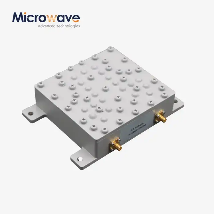
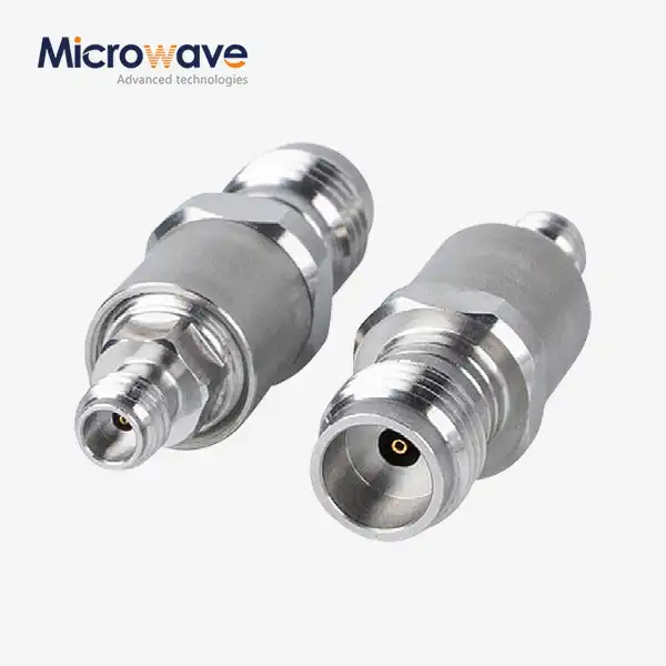
The coplanar nature of cpw waveguide structures provides significant advantages for hybrid and monolithic microwave integrated circuit applications. Traditional waveguide technologies often require complex via structures or substrate backside processing to establish ground connections, adding manufacturing complexity and potential failure points. In contrast, the cpw waveguide places all conductors on a single surface, simplifying fabrication processes and enabling straightforward attachment of both shunt and series circuit elements. This accessibility proves particularly valuable when integrating active devices such as transistors or diodes, as well as passive components including capacitors and resistors. Advanced Microwave Technologies Co., Ltd. capitalizes on these integration advantages by offering customizable cpw waveguide solutions tailored to specific application requirements. Their model ADM-20CPWST1 exemplifies this approach, featuring a frequency range extending from DC to twenty gigahertz with insertion loss limited to one point five decibels maximum. The aluminum construction provides excellent thermal conductivity, allowing efficient heat dissipation even under high-power operating conditions. This thermal management capability becomes increasingly important as modern communication systems push toward higher frequencies and power levels, where thermal-induced performance degradation can severely compromise system reliability.
The planar geometry of cpw waveguide also facilitates the implementation of complex circuit functions within minimal footprint. Multiple cpw waveguide lines can be routed in close proximity with well-defined coupling characteristics, enabling the realization of coupled-line filters, directional couplers, and power dividers. The ground planes provide natural isolation between adjacent signal paths, reducing unwanted crosstalk that might otherwise degrade circuit performance. This isolation property, combined with the inherent ease of fabrication, makes cpw waveguide an ideal choice for dense circuit layouts where space constraints demand creative solutions without compromising electrical performance.
Applications of CPW Waveguide in Nonreciprocal Gyromagnetic Devices
Resonant Isolators and Phase Shifter Implementation
The original motivation for developing coplanar waveguide technology stemmed from the need to integrate nonreciprocal gyromagnetic devices into planar circuit configurations. Isolators and circulators based on ferrite materials require specific magnetic field orientations to achieve their nonreciprocal behavior. Traditional rectangular waveguide structures naturally provide appropriate field patterns, but their three-dimensional geometry makes integration with planar circuits challenging. The cpw waveguide solves this problem by generating the necessary rotating magnetic field components within a completely planar structure. When a microwave signal propagates along a cpw waveguide, the magnetic field exhibits both longitudinal and transverse components due to the asymmetric electric field distribution at the air-dielectric interface. These field components can be decomposed into two counter-rotating circular polarizations. By placing magnetized ferrite material adjacent to the cpw waveguide gaps, designers can exploit the differential absorption or phase shift experienced by these two polarization senses. This phenomenon enables the construction of resonant isolators that allow signal transmission in one direction while absorbing energy traveling in the reverse direction, or differential phase shifters that impart controllable phase shifts depending on signal propagation direction.
Advanced Microwave Technologies Co., Ltd. has extensively developed expertise in optimizing cpw waveguide geometries for gyromagnetic device applications. Their design methodology accounts for the complex interaction between the cpw waveguide electromagnetic fields and the magnetized ferrite elements. By carefully controlling the gap dimensions and center conductor width, engineers can tailor the magnetic field strength and polarization characteristics to match specific ferrite material properties. This optimization ensures maximum nonreciprocal effect while minimizing insertion loss in the forward transmission direction, delivering practical devices suitable for demanding applications in radar systems, satellite communications, and electronic warfare equipment.
Modern Applications Across Multiple Technology Domains
Beyond the original gyromagnetic device applications, cpw waveguide technology has found widespread adoption across numerous modern microwave system domains. In fifth-generation wireless communication networks, cpw waveguide structures serve as critical interconnects between antennas, filters, and transceiver components operating at millimeter-wave frequencies. The low-loss characteristics of properly designed cpw waveguide enable efficient signal transmission even at frequencies approaching one hundred ten gigahertz, where traditional microstrip lines suffer from excessive losses. The planar geometry facilitates integration with advanced antenna arrays, enabling beamforming networks and phased array systems essential for fifth-generation base stations and user equipment. Radar and remote sensing applications benefit tremendously from cpw waveguide implementation. Automotive radar systems operating at seventy-seven gigahertz utilize cpw waveguide feed networks to distribute signals between multiple antenna elements with precise amplitude and phase control. The excellent impedance control inherent to cpw waveguide designs ensures minimal signal reflections that could otherwise create false targets or degrade detection range. Weather monitoring radars similarly employ cpw waveguide technology to achieve the wide bandwidth and low noise performance necessary for accurate precipitation measurement and storm tracking capabilities.
Satellite communication systems represent another critical application domain where cpw waveguide technology delivers substantial advantages. The lightweight planar construction reduces overall payload mass compared to traditional waveguide implementations, a consideration of paramount importance for space applications where launch costs scale directly with weight. Advanced Microwave Technologies Co., Ltd.'s cpw waveguide products meet the stringent reliability requirements for space environments while providing excellent thermal stability across the extreme temperature ranges encountered during orbit. The good heat dissipation properties enabled by adjacent ground planes help maintain stable electrical performance even under the high-power conditions typical of satellite transmitter final stages. In microwave integrated circuit applications ranging from power amplifiers to frequency converters, cpw waveguide serves as the foundational transmission line structure. The ease of integrating both active and passive components onto cpw waveguide lines simplifies circuit design and improves manufacturability. Advanced Microwave Technologies Co., Ltd. supports these applications through comprehensive OEM services that provide customized cpw waveguide solutions tailored to specific circuit requirements. Their engineering team collaborates closely with clients to optimize conductor widths, gap spacings, and substrate properties, ensuring optimal performance for each unique application scenario.
Technical Specifications and Design Flexibility
The versatility of cpw waveguide technology derives largely from its inherent design flexibility. Unlike waveguide structures with fixed cutoff frequencies determined by physical dimensions, cpw waveguide can be scaled to operate across an extremely wide frequency range. Advanced Microwave Technologies Co., Ltd. offers cpw waveguide products spanning from DC through twenty gigahertz, with laboratory capabilities extending to one hundred ten gigahertz for specialized applications. This frequency agility makes cpw waveguide suitable for everything from relatively low-frequency industrial, scientific and medical band applications through cutting-edge millimeter-wave communication and sensing systems.
The characteristic impedance of cpw waveguide structures can be precisely tailored through geometric parameter adjustment. By varying the ratio of center conductor width to gap spacing, designers can achieve impedances ranging from a few ohms to several hundred ohms, although most practical applications target the standard fifty-ohm impedance common in microwave systems. Advanced Microwave Technologies Co., Ltd.'s design capabilities enable impedance tolerance within plus or minus five percent, ensuring compatibility with standard components and minimizing return loss. The voltage standing wave ratio specification of less than one point three across the full bandwidth demonstrates the excellent impedance matching achievable with properly designed cpw waveguide structures. Material selection plays a crucial role in optimizing cpw waveguide performance for specific applications. Advanced Microwave Technologies Co., Ltd. utilizes high-quality aluminum for conductor fabrication, providing excellent electrical conductivity while maintaining mechanical durability. The natural color anodizing surface treatment protects against environmental degradation without introducing significant additional loss. For applications requiring enhanced dielectric properties, alternative substrate materials including alumina ceramics or specialized microwave laminates can be incorporated. The company's extensive experience with diverse material systems enables optimal material choices that balance electrical performance, mechanical robustness, thermal characteristics, and cost considerations.
Quality Assurance and Manufacturing Excellence
Advanced Microwave Technologies Co., Ltd. maintains rigorous quality control throughout every stage of cpw waveguide production. The company's ISO 9001:2015 certification reflects comprehensive quality management systems that ensure consistent product performance. From initial material inspection through final electrical testing, multiple verification steps confirm that each cpw waveguide assembly meets or exceeds specifications. The state-of-the-art twenty-four meter microwave darkroom enables precise characterization of cpw waveguide electrical properties under far-field conditions, providing measurement accuracy essential for validating theoretical designs and ensuring product reliability. Environmental responsibility forms an integral component of the manufacturing process, as evidenced by ISO 14001:2015 certification. Advanced Microwave Technologies Co., Ltd. implements sustainable practices that minimize waste generation and energy consumption while maintaining the precision necessary for high-performance cpw waveguide fabrication. The company's commitment to RoHS compliance ensures that all products meet stringent restrictions on hazardous substances, making them suitable for global markets with varying regulatory requirements. Employee safety receives paramount attention through adherence to ISO 45001:2018 occupational health and safety standards. The specialized equipment and processes involved in cpw waveguide manufacturing demand well-trained personnel operating under carefully controlled conditions. Advanced Microwave Technologies Co., Ltd. provides comprehensive training programs and maintains detailed safety protocols that protect workers while ensuring consistent product quality. This focus on human factors contributes to low defect rates and high manufacturing yields, ultimately benefiting customers through reliable delivery schedules and competitive pricing.
Conclusion
CPW waveguide technology offers unmatched advantages for modern microwave systems requiring planar integration, low loss transmission, and compatibility with nonreciprocal gyromagnetic components across diverse applications from satellite communications to advanced radar systems.
Cooperate with Advanced Microwave Technologies Co., Ltd.
As a leading China cpw waveguide manufacturer, supplier, and factory, Advanced Microwave Technologies Co., Ltd. delivers high quality cpw waveguide solutions at competitive prices with cpw waveguide for sale globally. With over twenty years of microwave expertise, ISO certifications, and a state-of-the-art twenty-four meter darkroom testing facility, we provide customized OEM services from prototyping through production. Our cpw waveguide wholesale options serve aviation, aerospace, defense, satellite, and telecommunications industries worldwide. Whether you need standard products or custom designs, our expert team ensures fast delivery and comprehensive technical support. Contact craig@admicrowave.com today to discuss your requirements and discover why global clients trust us as their China cpw waveguide supplier for critical microwave applications.
References
1. Wen, C.P. Coplanar Waveguide: A Surface Strip Transmission Line Suitable for Nonreciprocal Gyromagnetic Device Applications. IEEE Transactions on Microwave Theory and Techniques, Volume 17, Issue 12, December 1969.
2. Simons, R.N. Coplanar Waveguide Circuits, Components, and Systems. John Wiley and Sons, 2001.
3. Ghione, G., Naldi, C.U. Coplanar Waveguides for MMIC Applications: Effect of Upper Shielding, Conductor Backing, Finite Extent Ground Planes, and Line-to-Line Coupling. IEEE Transactions on Microwave Theory and Techniques, Volume35, Issue 3, March 1987.
4. Wolff, I. Coplanar Microwave Integrated Circuits. John Wiley and Sons, 2006.
_1733738410152.webp)