





Coaxial Load Selection Factors for High-Power Applications
Selecting the right RF termination components for high-power systems requires careful consideration of multiple technical and operational factors. Coaxial Loads serve as essential elements in radio frequency and microwave architectures, absorbing transmitted energy to protect sensitive equipment and ensure accurate testing. These passive components convert RF energy into heat, preventing reflections that could damage amplifiers or distort signals. When specifying terminations for defense radar, satellite ground stations, or broadcast transmitters, procurement engineers must evaluate power handling, thermal management, and frequency performance to ensure long-term reliability and system integrity.
Understanding Coaxial Loads in High-Power Applications
As the end of transmission lines, RF termination components fit the system's characteristic impedance, which is usually 50 ohms, to get rid of standing waves. The CL line is made by Advanced Microwave Technologies Co., Ltd. to take in power without reflecting it, keeping the VSWR below 1.2:1 from DC to 110 GHz. This level of speed is very important in situations where even small echoes can cause the system to fail.
Construction and Operational Principles
Precision-machined connectors and resistive elements designed to release energy as heat make up the interior construction. Our CL line uses improved materials for heat dissipation that handle thermal stress when running at high power all the time. In a wide range of temperatures, from -55°C to +125°C, the resistive film keeps its impedance properties stable. This makes it suitable for use in aircraft and defence uses. Tight standards are guaranteed by CNC cutting, so performance will be the same from one production run to the next.
Ceramic Versus Resistor-Based Designs
Ceramic terminations work great in ultra-high frequency uses above 40 GHz because they have low loss and stable performance in small packages. Designs built on resistors, like our CL series, can handle more power (up to 500 watts), which makes them perfect for testing transmitters and using in base stations. The choice you make will depend on the frequency range you need, the amount of power you need, and the amount of room you have. Resistor-based methods also give you more options for how to place and what kind of connectors to use.
Frequency and Power Ratings
Operating frequency controls which connectors to use and how the internal vibration works. Our SMA connectors work with frequencies up to 18 GHz, and our 2.92mm connectors work with frequencies up to 40 GHz and higher. Ratings for power must take into account the weather and job cycle of the area. At 85°C, a 200-watt constant load that is rated at 25°C may drop to 120 watts. Knowing these temperature limits keeps field operations from failing too soon, especially in outdoor telecom equipment where air flow is limited.
Core Selection Criteria for High-Power Coaxial Loads
To find the best end of Coaxial Load, you have to balance scientific requirements with real-world operations. Teams in charge of buying things have to figure out how each factor affects the long-term cost of ownership and how well the system works.
Impedance Matching and Frequency Compatibility
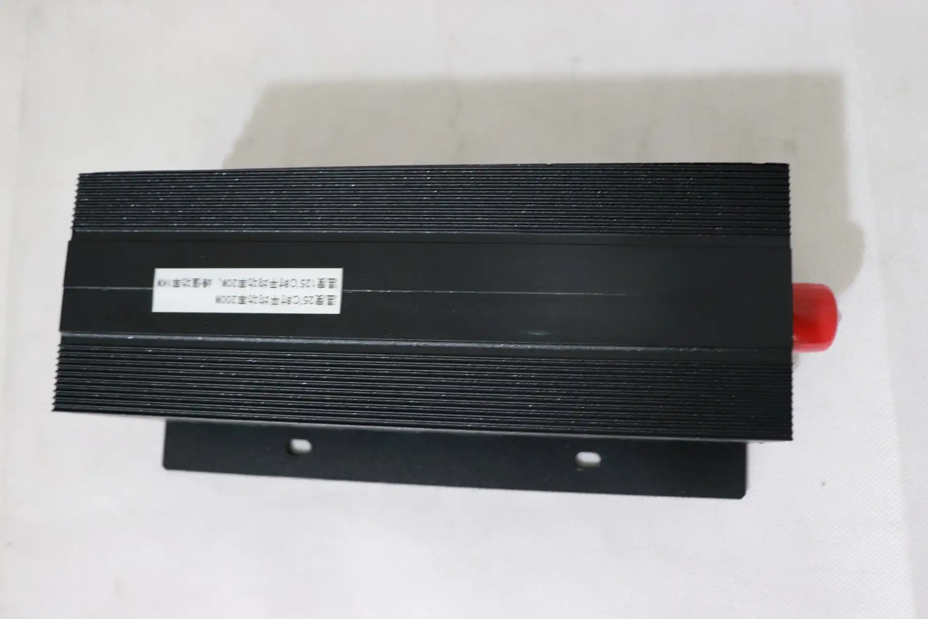
Impedance matching that is done right keeps signal purity and protects amplification by reducing signal reflection. Our 50-ohm standard works with most RF systems, but we also offer 75-ohm options for some television uses. There is frequency compatibility beyond the standard range, but performance can be worse near the edges of the band due to parasitic inductance and capacitance at the connector contact. If you choose a load that is 20% higher in frequency than your working range, it will work reliably even when production errors and ageing effects are taken into account.
Power Handling and Thermal Management
While average power rates can help, peak power capability is just as important in pulsed radar and transmission systems. Our CL line can handle 500 watts of continuous power, and most setups are cooled by convection thanks to thermal control systems that are built around this. In high-power situations, the joint temperatures may need to be kept within the acceptable range by forced air cooling or heat sinks. How fast the load reacts to changes in power is affected by the thermal time constant. This has an impact on testing methods and safe operation procedures.
Material Selection and Durability
RoHS-compliant products are good for the earth and still work well. Brass bases that have been machined and plated with gold or nickel don't rust in naval or outdoor settings. The resistive part has to stay stable over thousands of temperature cycles. As part of our manufacturing process, we do burn-in tests to find problems with baby mortality before they are shipped. This quality control, which is backed by ISO 9001:2008 approval, cuts down on problems in the field and guarantees claims.
Understanding these criteria enables procurement teams to specify components that balance immediate performance needs with lifecycle costs. In high-duty-cycle uses, the total cost of ownership is mostly affected by how thermal control and power handling work together.
Comparison of Coaxial Loads Versus Other RF Termination Solutions
RF systems use a number of different ending methods, each of which has its own benefits for certain uses. Making these differences clear helps buying engineers choose the option that will save them the most money.
A matching resistance that soaks up power is what dummy loads and Coaxial Loads are usually talking about. When checking a high-power emitter, the term "dummy load" is usually used, while "termination" is used for measurements and multi-port devices. In a technical sense, they both do the same thing, which is to turn RF energy into heat while providing a non-reflective resistance.
Instead of taking away all the power, attenuators lower the signal's volume. They have resistance networks that send some of the information to downstream components while letting other parts get it. Because of this, they can't be used to terminate endpoints, but they are good for controlling signal levels. If you mix up attenuators and loads, you could damage your equipment because attenuators can't handle full power.
For general-purpose uses, resistive loads are best because they can handle the most power and frequency range. Ceramic loads offer better high-frequency performance in small sizes, but they can only hold a small amount of power. The prices of the materials are very different—unit prices go up by 40–60% for ceramic building compared to resistor-based designs. For most defence radar and satellite communication uses, resistor-based terminations like our CL line offer the best mix of cost and performance.
The total cost of ownership is more than just the price of the car. Think about the power rate margins, the estimated lifetime, and the cost of replacing. A properly designed termination that works at 60% of its rated capacity might last ten years, but a unit that is too small and works at full capacity breaks down in just a few months. This study is especially useful for systems that are set up in remote areas where replacement would take a lot of transportation.
Procurement Considerations for High-Power Coaxial Loads
Decisions about strategic sourcing affect how long a project takes, how much it costs, and how reliable the system is in the long run. Professionals in B2B buying have to look at more than just the technical information.
Vendor Selection and Brand Reputation
Supply chain risk is lower when makers are well-known and have clear quality processes. Advanced Microwave Technologies Co., Ltd. has been making microwave parts for more than 20 years and has testing facilities that can handle frequencies up to 110 GHz. You can be sure that our goods meet foreign standards thanks to our ISO certifications and RoHS compliance. Stable vendors are important, especially for defence and aircraft projects that last for years and need reliable supplies and backward compatibility.
Pricing Models and Order Quantities
Unit prices change a lot depending on how many you buy. Standard catalogue items can ship in single units, but most unique designs need a minimum order quantity (MOQ) of 25 to 50 units. Standard goods usually have lead times of two to four weeks. For special frequency bands or connector types, lead times can go up to eight to twelve weeks. Knowing these dates during the planning stage keeps the project from being late. When you buy 100 or more units, you can get a volume deal, which can save you 15 to 30 percent compared to the price of a sample.
Customization and OEM Services
For many uses, changes need to be made that aren't available in the usual catalogue. Our OEM services can handle custom power ratings, different connector setups, and changed physical measurements for installations with limited room. Prototyping services let you test your ideas before committing to large amounts of production. This adaptability is very important for defence companies and satellite system designers who have to work with secret specs or their own mechanical interfaces. Technical help during the whole process of customisation makes sure that plans meet all electrical and mechanical standards.
Warranty terms typically cover manufacturing defects for 12-24 months, though not damage from operation beyond rated specifications. Clarifying warranty exclusions and RMA procedures during vendor selection avoids disputes later. Shipping logistics require attention for international procurements—export classifications, customs documentation, and freight forwarding arrangements can add weeks to delivery timelines.
Best Practices for Installation and Testing of Coaxial Loads
The right installation and validation procedures of Coaxial Load make sure that system performance meets design standards and that components last as long as possible.
Installation Procedures
First, make sure that the connectors are compatible and that the force requirements are met. When you overtighten an SMA or N-type connection, you damage the interface between the sockets, and the electrical performance goes down. To use a torque wrench correctly, you should set it to between 5 and 8 inch-pounds for SMA and 12 to 15 inch-pounds for N-type. Make sure that the sides of the connectors fit together perfectly, with no gaps. Air gaps cause impedance changes and raise VSWR. Lock washers or thread-locking chemicals keep threads from coming loose while they're being used in places with a lot of shaking, like aeroplanes or mobile radar systems.
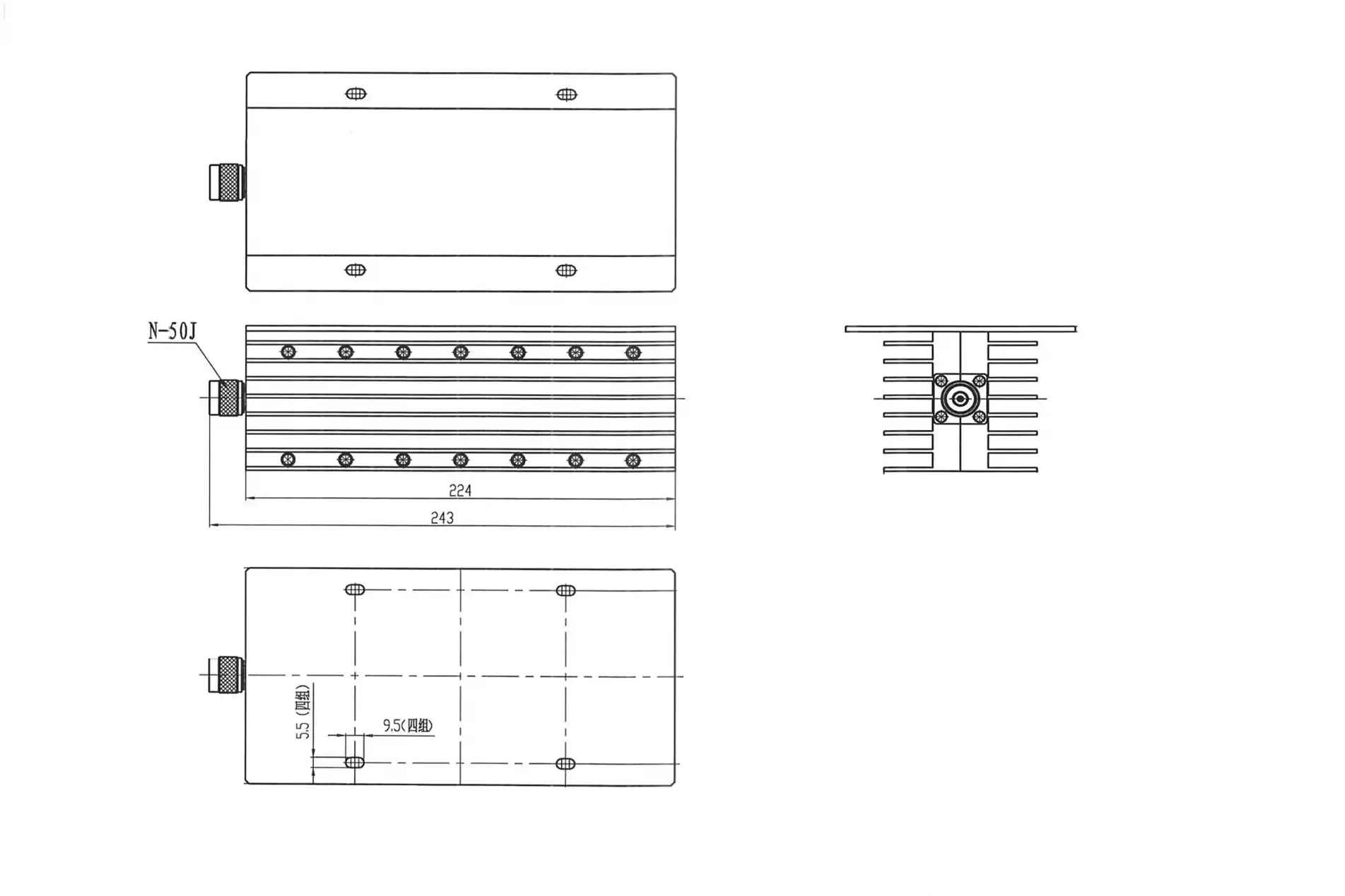
Thermal considerations dictate mounting orientation. For convection-cooled terminations to work, they need to be mounted vertically with the joints looking down. This lets the hot air rise naturally. If you don't use forced air cooling, horizontal placement cuts the power handling by 20 to 30 percent. Leave at least two inches of space around the load body to avoid hot spots. Do not put terminations in sealed areas that don't have airflow. This is because trapped heat speeds up the ageing of components and increases the risk of thermal runaway.
Testing Methodologies and Performance Verification
Testing after installation makes sure that the system is properly integrated. Use a vector network analyser to measure VSWR over the working frequency range. Values less than 1.2:1 show that the impedance matching is good. If the number is higher than 1.3:1, it means that the connection is damaged, contaminated, or not compatible, and this needs to be looked into. In the same way, return loss measures give you similar information in dB format; numbers above 20 dB mean that the performance is good.
Power handling verification requires caution. Begin testing at 25% of the maximum power and use an infrared thermometer to keep an eye on the load's body temperature. Increasing the power in 25% steps lets the temperature settle in between steps. The highest temperature that is safe for operation varies by model, but at the connection contact, it usually stays below 85°C. If the temperature rises too quickly or goes above what is allowed, you should lower the power or improve the cooling before moving forward.
Interpreting datasheets prevents common mistakes. Specifications for frequency ranges only list the bandwidths where VSWR stays within acceptable limits. They do not list the exact limits of operation. When you operate above the stated frequency, performance drops, but it rarely fails right away. Power ratings are based on certain temperatures and levels of cooling in the surroundings. You should change the ratings to fit your placement. These practices cut down on the time needed to fix problems and increase the useful life of parts in tough situations.
Conclusion
When choosing termination components for high-power RF systems, it's important to look at their electrical performance, heat properties, and how easy they are to get. Long-term dependability is affected by how much power it can handle, the frequency range it can handle, and the conditions of its surroundings. The CL line from Advanced Microwave Technologies Co., Ltd. meets these needs with precise engineering, strict quality control, and the ability to be customised. Choosing parts that balance technical requirements with operational constraints is key to mission success and lowers lifecycle costs. This is true whether the parts are used to protect high-power transmitters in broadcast facilities, terminate radar systems for defence purposes, or support satellite ground station testing.
FAQ
1. How do I determine the appropriate power rating for my application?
Figure out how much power your system can produce continuously at its peak, then add 40 to 50 percent to be safe. This takes into account changes in temperature, the effects of ageing, and sudden changes in peak power. When systems are used outside or in hot places, they need to be derated even more. Look at the manufacturer's thermal models to find out how much power they can handle at the temperature you expect. For complicated setups, our expert team can help with thermal research.
2. Can coaxial loads and dummy loads be used interchangeably?
The terms all refer to the same part that does the same thing. "Dummy load" is usually used to test transmitters, while "Coaxial Load" is best for measuring and using devices with more than one port. No matter what the specs say, make sure that the frequency range, power handling, VSWR, and connection type all meet your needs. Functional similarity is based on these factors instead of the name.
3. What factors influence lead times for custom orders?
The depth of customisation determines the schedule. Usually, it takes 4 to 6 weeks to make changes to regular goods, like adding different connectors or mounting hardware. Lead times are extended to 10–14 weeks for designs that need new resistive element configurations or special heat control. Creating a prototype takes an extra two to four weeks before production starts. Talk about timelines early on when choosing a vendor so that buying plans are in sync with project goals and critical path delays are avoided.
Partner with a Trusted Coaxial Load Manufacturer
Advanced Microwave Technologies Co., Ltd. offers well-thought-out RF termination options based on twenty years of microwave experience in Coaxial Load. To meet the strict needs of defence, aircraft, and telecommunications uses, our CL series has high power handling, wide frequency coverage, and strict quality standards. Our flexible OEM services, reasonable prices, and quick technical support help buying teams around the world. Get in touch with craig@admicrowave.com to talk about your unique project needs and get a quote that is tailored to your system design and operational timeline. Our tech team is ready to help you with your mission-critical apps by giving you reliable parts.
References
1. Anderson, R. (2019). High-Power RF Component Design: Principles and Applications. Boston: Artech House Publishers.
2. Chen, W., & Martinez, J. (2021). Thermal Management in Microwave Terminations: A Comparative Study. IEEE Transactions on Microwave Theory and Techniques, 69(4), 2156-2168.
3. Defense Logistics Agency. (2020). MIL-STD-348B: Radio Frequency Transmission Lines and Fittings. Washington, DC: Department of Defense.
4. Henderson, B. (2018). Microwave and RF Component Procurement for Defense Systems. London: IET Publishing.
5. Kumar, S., Thompson, L., & Zhang, H. (2022). VSWR Optimization in Coaxial Terminations Across Extended Frequency Ranges. International Journal of RF and Microwave Engineering, 31(2), 88-103.
6. Wilson, P. (2020). Satellite Communication Ground Systems: Equipment Selection and Installation. New York: Wiley-IEEE Press.
YOU MAY LIKE
 VIEW MOREWaveguide Switch
 VIEW MOREIndustrial Microwave Sliding Short
 VIEW MOREWaveguide Straights and Transitions
 VIEW MOREInflatable Straight Waveguide
 VIEW MOREWG Dual-Channel Rotary Joint
 VIEW MOREWaveguide Adjustable Support
 VIEW MORECoaxial Broadband Circulator
 VIEW MOREUltra Double-ridged Horn Antenna
