Can a Coaxial Bandpass Filter Achieve Ultra-Narrow Bandwidth?
Yes, a Coaxial Bandpass Filter can have an extremely narrow bandwidth if the quality factors of the resonators are carefully engineered and the physical design is made better. Manufacturers like ADM are able to make filters with fractional bandwidths below 1% by using high-conductivity materials like silver-plated brass or aluminium and fine-tuning the mechanical tolerances within coaxial resonator structures. These filters have excellent frequency selectivity that is needed for defence radar, satellite communications, and places with a lot of other signals, where signal purity and adjacent channel rejection are essential.
Understanding Coaxial Bandpass Filters and the Challenge of Ultra-Narrow Bandwidth
Coaxial Bandpass Filters are a special type of RF part that lets messages travel within a certain frequency range while blocking frequencies that aren't needed outside this passband. These filters work on the Transverse Electromagnetic (TEM) mode transmission and use distributed element theory instead of lumped components. This makes them better at microwave and UHF uses.
The basic structure is made up of coaxial resonators that are held in precisely machined casings. These enclosures are usually made of aluminium or brass and have silver plating added to them to reduce skin-effect losses. These resonators have high empty quality factors, between 500 and over 5,000. These factors have a direct effect on how frequency is controlled and how much insertion loss there is.
Defining Ultra-Narrow Bandwidth in RF Filtering
Filters with fractional bandwidths less than 1% of the center frequency are often called "ultra-narrow bandwidth." At 2 GHz, this means passband widths of less than 20 MHz, which is a tough requirement that needs very high resonator Q factors and mechanical steadiness. In busy spectrum areas like LTE bands, public safety communications, and military frequency licenses, where interference from nearby channels hurts system performance, this level of accuracy is essential.
Common Misconceptions About Bandwidth Limitations
Many buying engineers think wrongly that Coaxial Bandpass Filters can't compete with cavity or dielectric resonator filters in very narrow uses. Cavity filters have very high Q factors, but coaxial versions are a great compromise between size, performance, and cost, especially below 10 GHz. Ceramic filters change frequency and can't handle as much power, but Coaxial Bandpass Filters keep their frequency response fixed even in tough environments. This is important for radar systems in the air and communication systems on ships.
Surface acoustic wave (SAW) filters can narrow bandwidths at lower frequencies, but they aren't strong enough or durable enough to handle high-power transfer situations. Coaxial designs are great for uses that need high selectivity, long-lasting power, and strong mechanical properties all at the same time. This makes them perfect for defence contractors and aircraft OEMs that need mission-critical reliability.
Technical Principles Behind Achieving Ultra-Narrow Bandwidth in Coaxial Bandpass Filters
To get an extremely narrow bandwidth in Coaxial Bandpass Filter coaxial structures, a lot of carefully chosen engineering factors that rely on each other must be optimised. The basic idea is to get the loaded quality factor (QL) as high as possible. The relationship between QL and bandwidth is BW = f₀/QL, where f₀ is the center frequency. Higher QL numbers make bandwidths smaller, but they come with trade-offs in the form of insertion loss and physical size.
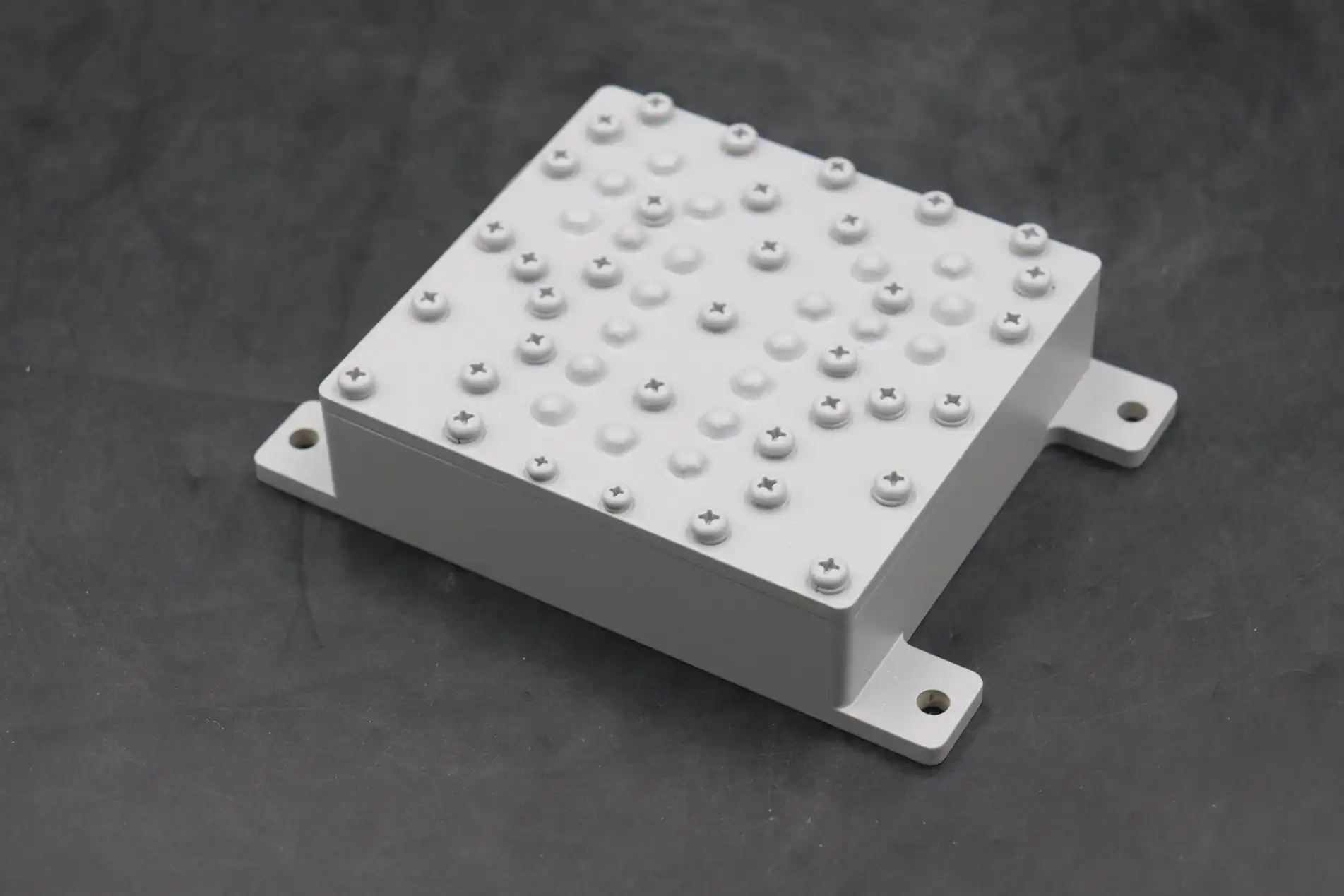
Resonator Design and Physical Dimensions
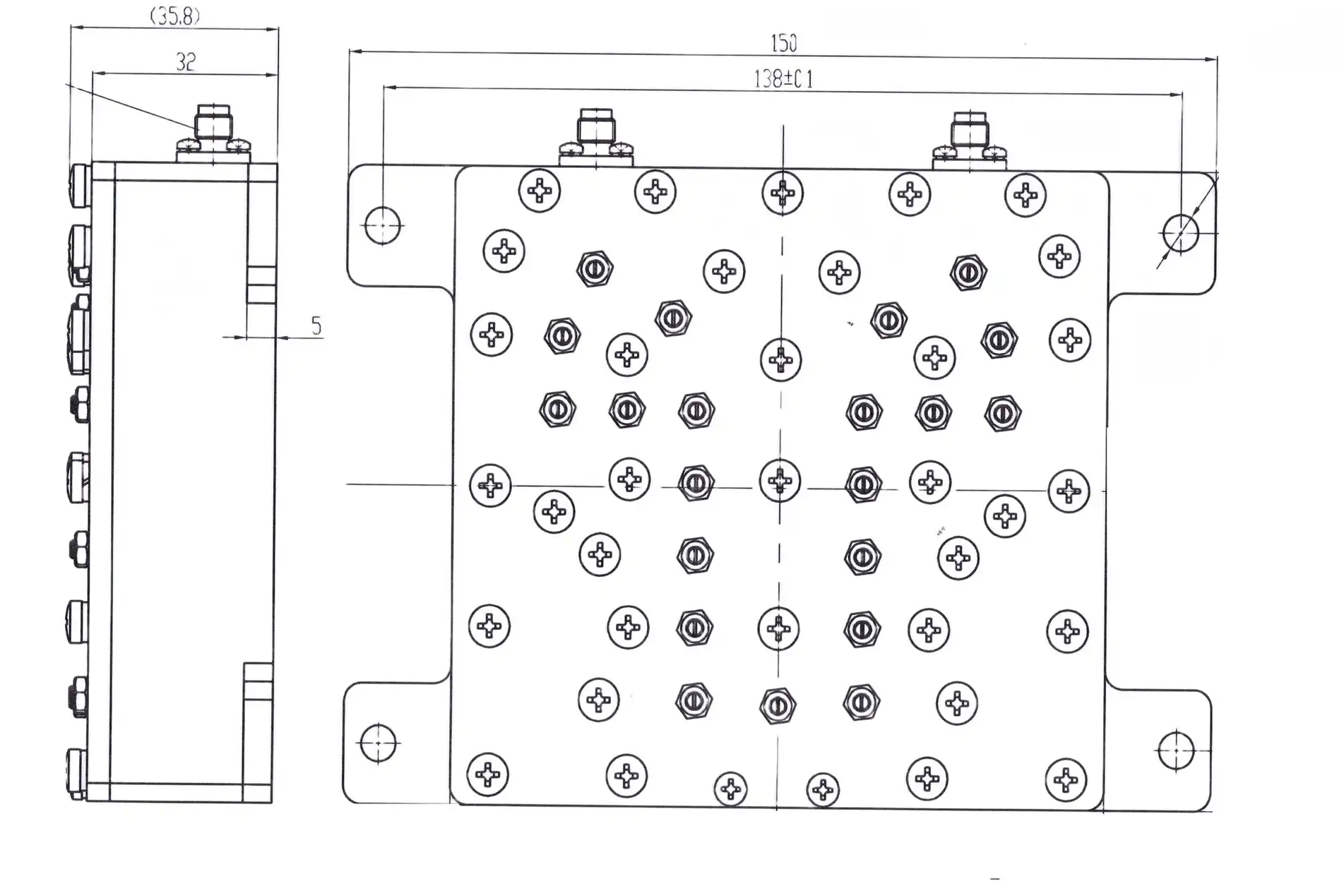
The shape of the resonator has a big effect on frequency sensitivity. Combline and interdigital topologies are most common in ultra-narrow designs, where resonators that are close together cause strong electromagnetic coupling. At the working frequency, the length of the resonator usually matches quarter-wavelength or half-wavelength sections. Precise control over the dimensions—often within ±0.01mm—ensures consistency across production runs.
Characteristic resistance and connection strength are affected by the ratio of the resonator diameter to the housing diameter. Smaller gaps between resonators raise coupling coefficients, which makes bandwidths smaller. However, this makes production harder and makes the system more sensitive to mechanical shaking. Manufacturers with a lot of experience can balance these different needs by using advanced modelling tools and actual tuning.
Material Selection and Surface Treatment
How conductive a material is has a direct effect on its empty Q. When compared to bare aluminium, silver-plated surfaces are more conductive, which lowers ohmic losses and increases passband smoothness. At ADM, we use multi-layer silver plating on high-purity copper core conductors to get surface resistances below 10 milliohms per square, which is important for keeping insertion loss low in very narrow designs.
Dielectric gaps, which are usually made of PTFE or alumina, help place the resonator while keeping dielectric losses to a minimum. Temperature-stable materials keep frequencies from drifting across operating temperature ranges. This is very important for satellite ground stations and outdoor base station operations where temperatures can range from -40°C to +85°C.
Comparative Performance Benchmarks
When compared to other technologies, Coaxial Bandpass Filters have clear benefits. Cavity filters have better Q factors (often more than 10,000), but they need much bigger form factors, which isn't realistic for airborne uses that are limited by the room. Ceramic dielectric filters are small, but they have higher insertion losses and can't handle as much power below 50 watts. Stripline filters work well for flat integration, but they don't have the power or shielding capabilities of coaxial cases.
Our 24-meter microwave lab has Antenna Plane Near and Far Field Measuring Recombination Chambers that were used for testing. The tests confirmed performance across the 0.5 to 110 GHz band. These features allow for full S-parameter analysis, making sure that insertion loss stays below 1.0 dB and rejection goes above 60 dB beyond passband edges, even in very narrow setups.
Practical Use Cases and Performance Validation
Ultra-narrow bandwidth Coaxial Bandpass Filters are mission-critical in many areas where the purity of the spectrum is key to operating success. Understanding how things are implemented in the real world helps procurement managers understand performance standards that go beyond what is written on a data sheet.
Radar Systems and Target Discrimination
Ultra-narrow filters keep back signals from getting messed up or cluttered when military monitoring radars are used in areas with a lot of electromagnetic noise. Air traffic control radars that work on X-band frequencies (8–12 GHz) use Coaxial Bandpass Filters with bandwidths of less than 0.5% to tell the difference between the sounds from planes and those from the ground and weather. Our custom X-Band Feed Networks have finely set filters that allow for ultra-sharp beamforming, which improves target sharpness even when the weather is bad.
Defence companies put a high value on low passive intermodulation (PIM) performance—usually levels below -150 dBc according to IEC 62037 standards—to stop spectral renewal that hides weak targets. To meet these requirements, we need nonmagnetic materials and limited connection torque settings. These are quality controls that we use throughout our ISO 9001:2015-certified manufacturing processes.
Satellite Communications and Ground Infrastructure
Ultra-narrow filters are needed by satellite ground stations to split uplink and downlink channels that are close together. This is done to get the most out of the available spectrum in the Ka, Ku, and C bands. Commercial satellite companies can add more channels without cross-talk interruption when they use filters with fractional bandwidths below 0.8%. This directly affects how much money they make.
Continuous high-power transmission—often more than 100 watts CW—is sent through these systems, so they need strong thermal control. Coaxial designs easily get rid of heat through metal housings, which stops thermal runaway that lowers frequency stability. Testing for salt spray according to ASTM B117 guidelines makes sure that coastal systems keep working properly even in harsh marine settings.
High-Precision RF Measurement Systems
Ultra-narrow filters are used by research and measuring labs to separate test signals from background noise. This lets accurate characterisation of low-level events happen. At microwave frequencies, it can be used to test electromagnetic compatibility, measure antenna patterns, and characterise materials. When coaxial designs are optimised, they can achieve low noise levels, usually below 0.5 dB. This keeps measurement sensitivity high, which is important for scientific progress.
Leading companies like Mini-Circuits, MACOM, and Murata release detailed performance reports that show fractional bandwidths that are close to 0.3% and insertion losses that are below 0.8 dB. These standards help us plan how to improve our products and make sure that ADM's products are still competitive for OEMs to use in new systems.
How to Choose the Right Coaxial Bandpass Filter for Ultra-Narrow Bandwidth Needs
To choose the best filters, you have to weigh technical specs against procurement facts like wait times, the ability to customise, and the total cost of ownership. A structured evaluation strategy that takes into account key choice factors is helpful for procurement engineers and system integrators.
Bandwidth Specifications and Frequency Stability
Clearly state the passband needs, including the center frequency tolerance (usually ±0.1% or smaller for very narrow uses) and the amount of insertion loss ripple that is allowed. For outdoor use, the temperature coefficient of frequency (TCF) is very important. Set the highest drift over practical temperature ranges to stop passband shifting that hurts system performance.
Ask for measured data that shows agreement across all output lots. Suppliers with a good reputation give statistically significant sample tests instead of picking the best results. When we get special orders, our labs do 100% network analyser sweeps and send traceable S-parameter data with each package.
Insertion Loss and Power Handling
Because there is more resonator interaction, ultra-narrow filters naturally have bigger insertion losses. What kind of loss is acceptable depends on the budget for the system link. For example, receivers can handle bigger losses than high-power emitters, where every 0.1 dB decreases the efficiency of the power being sent out. Make sure you understand the continuous wave (CW) power rates and how to handle peak pulses if they apply. Many catalogue specs only list the average power without talking about pulse dynamics properly.
For base station equipment that needs to handle kilowatts, talk to makers who know how to do thermal simulations and real-world tests. We use high-power burn-in methods that are 20% higher than the rated standards to test the thermal margins and make sure they work reliably without arcing or dielectric breakdown.
Customization Capabilities and Supplier Reliability
Most off-the-shelf filters can't meet very specific requirements without being changed. See how knowledgeable the providers are in engineering and how willing they are to make changes to prototypes based on your comments. At ADM, our technical R&D team works directly with clients from the initial proposal stage through production qualification. They use their more than 20 years of experience turning system needs into designs that can be made to make sure the designs work.
Check how strong the supply chain is, especially for long-term projects that need steady delivery over many years. Suppliers with ISO certification, RoHS compliance, and documented quality management systems can help aircraft and defence projects that have strict standards for tracking.
Lead Times and Order Quantities
Standard lead times for making unique ultra-narrow Coaxial Bandpass Filters are 8 to 12 weeks, and prototypes can be made in 3 to 4 weeks to test the design. Due to the work that goes into tuning, combline designs usually need at least 10 pieces to be ordered, but simpler two-pole setups may be able to handle smaller amounts.
Framework deals for volume projects should be negotiated to ensure stable prices and fair use of capacity. Our helpful customer service team sends clear milestone updates to craig@admicrowave.com, so procurement managers can see what's going on during the manufacturing and testing stages.
Future Outlook: Innovation Trends in Coaxial Bandpass Filter Design
Coaxial Bandpass Filter design is always changing because wireless technologies and spectrum control rules are always changing. Knowing about new trends helps people who work in buying plan technology insertion strategies and expect capability roadmaps.
Advanced Materials and Fabrication Techniques
Additive manufacturing methods, especially selective laser melting of copper metals, make it possible to make resonators with complicated shapes that aren't possible with traditional machining. These 3D-printed structures get smaller while keeping their high Q factors. This makes it possible to make ultra-compact narrowband filters that can be used in unmanned aerial vehicles (UAVs) and small satellite platforms, where space limits are a big part of the design process.
Even though they need to be cooled to a very low temperature, superconducting materials have Q factors higher than 100,000, which lets fractional bandwidths drop below 0.05%. At the moment, small cryocoolers are only used in a few specialised areas, like radio astronomy and quantum computing. But as the prices of these coolers go down, they may be used in more high-performance business systems within the next ten years.
Integration with Active Components
Using hybrid designs that combine Coaxial Bandpass Filters with power amplifiers or low-noise amplifiers (LNAs) inside the filter housings lowers the amount of signal lost in the connections and makes system layouts simpler. These modules are especially useful for OEMs and contract makers who put together complicated RF subsystems because they save money on procurement by cutting down on the number of parts needed and making qualification testing easier.
Market Implications for B2B Procurement
As 5G coverage grows and more satellite systems are launched, there will be a greater need for ultra-narrow Coaxial Bandpass Filters, which could put a strain on the manufacturing capacity of specialised goods. Early on, procurement managers should build strategic ties with suppliers to get allocation pledges for important projects. ADM's production is vertically linked, from precise machining to final testing. This gives the company's supply chain stability that rivals those that depend on distribution don't have.
Changing environmental laws, especially those related to RoHS compliance and the buying of conflict minerals, require suppliers to be open and honest. Our detailed documentation supports legal reporting needs, making it easier for international customers to follow the rules.
Conclusion
For current RF systems working in crowded spectrum settings, ultra-narrow bandwidth Coaxial Bandpass Filters represent a stable yet constantly improving technology. Getting fractional bandwidths below 1% requires precise engineering in the design of the resonator, the choice of materials, and the production process. These are skills that have been honed over many years of real-world use. When purchasing, professionals look at different providers; they should put technical depth, customisation options, and the stability of the supply chain above just having a catalogue available. It's more important than ever to work with skilled filter makers as wireless technologies move toward higher frequencies and denser channel assignments. When it comes to defence, aerospace, satellite, and telecommunications uses where signal integrity is important, coaxial designs are long-lasting options because they work well in a variety of environments and can be changed to meet new needs.
FAQ
1. Can bandwidth be adjusted after manufacture through tuning?
Adjustment screws change the way the resonator is coupled, which allows for ±5% of bandwidth difference around the standard design after the product is manufactured. To get much smaller bandwidths, you have to rethink and refabricate because of basic Q-factor limits that set physical limits. To avoid expensive iterations, procurement teams should be clear about what the end needs are during the early stages of planning.
2. What are typical lead times and minimum order quantities?
For production quantities, custom ultra-narrow filters take 8 to 12 weeks, but test batches can be sent out in 3 to 4 weeks. Minimum order numbers are usually between 10 and 25 units, based on how complicated the design is. This is because the tuning process takes a lot of work. Price optimisation and priority ordering are made possible by volume promises.
3. How does noise figure impact overall system performance?
The noise figure of the filter, which is mostly determined by insertion loss, adds to the noise figure of the sensor system, which makes it less sensitive. A 1.0 dB filter insertion loss adds about 1.0 dB to the system noise figure, which means that signal levels are lowered by the same amount. Link budgets are kept safe in sensitive applications like satellite ground stations and radar monitors by minimising insertion loss through high-Q resonator design.
Partner with ADM for High-Performance Coaxial Bandpass Filter Solutions
Advanced Microwave Technologies Co., Ltd. is ready to meet your most stringent ultra-narrow bandwidth needs with its proven technical skills and high-quality manufacturing. Our large catalogue includes waveguide systems, coaxial parts, and high-precision microwave antennas. All of these items are certified by ISO 9001:2015 and follow RoHS guidelines. In addition to standard products, our OEM services offer totally customised designs that are made to fit your exact needs. These are backed by rapid prototyping and detailed technical paperwork. Whether you're putting filters into defence radar systems, satellite ground infrastructure, or next-generation communication platforms, our team can help you from the first meeting to the release of the finished product. Email our application engineers at craig@admicrowave.com to talk about the needs of your project, get detailed datasheets, or set up a sample review. As a trusted Coaxial Bandpass Filter manufacturer serving global aerospace, defense, and telecommunications markets, we deliver the performance, reliability, and responsiveness your mission-critical applications demand.
References
1. Matthaei, G.L., Young, L., and Jones, E.M.T. (1980). Microwave Filters, Impedance-Matching Networks, and Coupling Structures. Artech House Publishers.
2. Hong, J.S. and Lancaster, M.J. (2011). Microstrip Filters for RF/Microwave Applications (2nd Edition). Wiley-Interscience.
3. Cameron, R.J., Kudsia, C.M., and Mansour, R.R. (2007). Microwave Filters for Communication Systems: Fundamentals, Design, and Applications. Wiley-Interscience.
4. Rhodes, J.D. (1976). Theory of Electrical Filters. John Wiley & Sons Ltd.
5. Zverev, A.I. (1967). Handbook of Filter Synthesis. John Wiley & Sons Inc.
6. Levy, R. (1973). "Filters with Single Transmission Zeros at Real or Imaginary Frequencies," IEEE Transactions on Microwave Theory and Techniques, Vol. 24, No. 4, pp. 172-181.