





Avoid These Mistakes When Specifying a Coaxial Directional Coupler
Many people choose the wrong coaxial directional coupler by failing to state the purpose. Selecting the wrong frequency range. Selecting the wrong coupling factor. Neglecting directivity and insertion loss. Underestimating power handling. Mismatching connectors or impedance. Trusting a datasheet without test data. That’s because each error may create inaccurate data, excess heat, signal loss, or post hoc alterations. This article was written to assist RF engineers, procurement teams, and OEM purchasers in avoiding these expenditures. Follow these steps, and you should have a clear list of what you want. This will also allow builders to acquire quotations and perform the project correctly the first time. A coaxial directional coupler samples a tiny portion of the RF power travelling in one direction on a transmission line. Engineers use it to transmit, calibrate, and check VSWR. Plus they utilise it to monitor forward and reflected power. Not always the best idea to base your choice on pricing, kind of connection, or one particular coupling value. Make sure you write down your criteria clearly, so you can receive the best costs when you enquire for estimates.
Mistakes in Defining the Application, Frequency, and Coupling
The first three mistakes are made before the supplier shows up. When you get them right, it's easier to choose what to do next.
Mistake 1: Choosing a Coupler Without Defining the RF Application
Start with the job, not the part number. A coupler that checks on a transmitter should be different from one that checks on antennas, RF, or amplifiers for safety. There should be little main-line loss and a lot of power for monitoring transmitters. It is best to test antennas with high directivity. The calibration work says that flat coupling over a wide band is best.
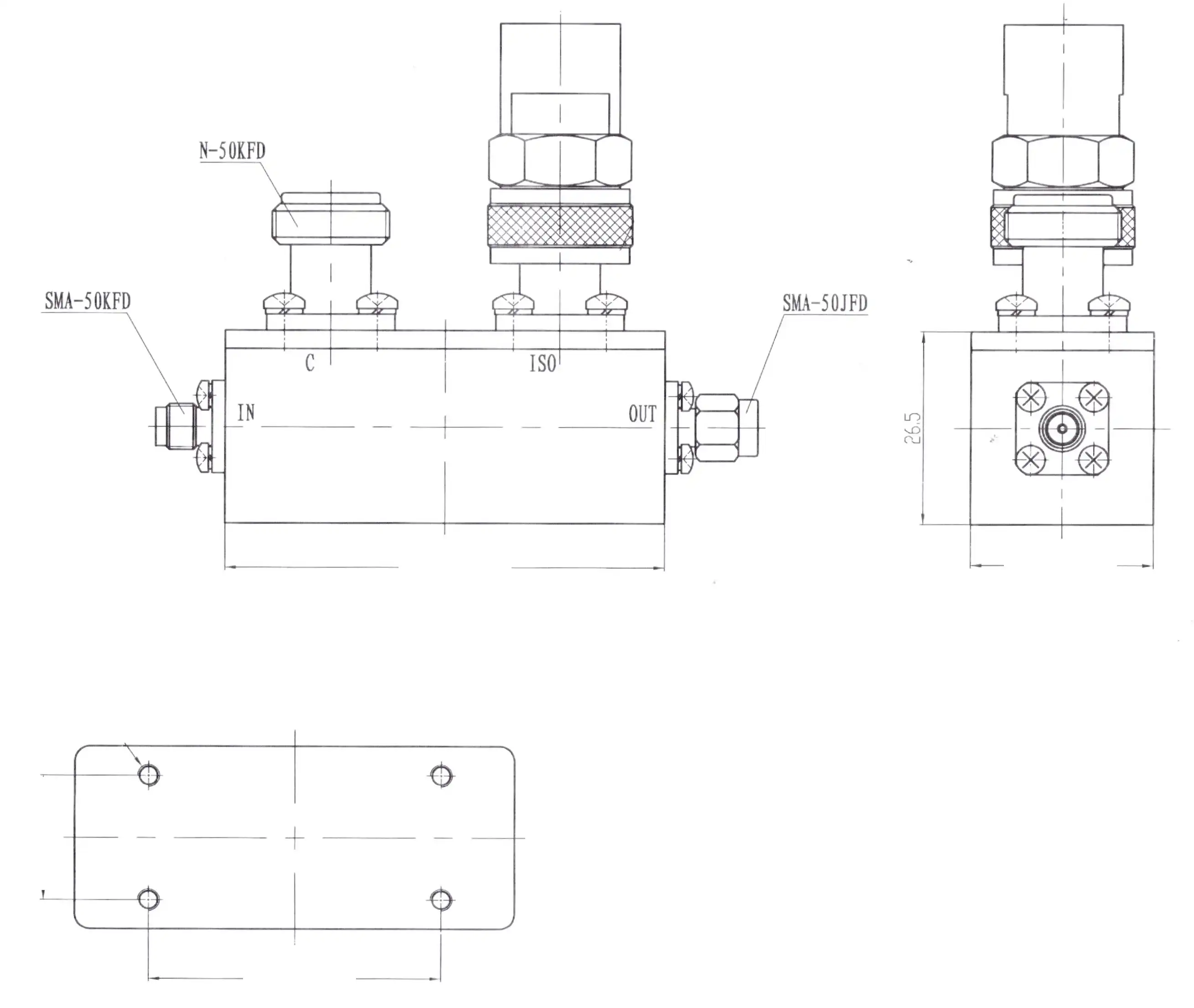
Find out about the four ports. It is sent through the input and output of the main line. That part that was sampled is sent through the coupled port. There are two-way designs, and the isolated port samples the other way. It usually ends in a load or a second measurement path.
Also, make sure you have the right coupler. Take power from one source and send it to another. A simple tap is what an RF sampler is, and an attenuator does nothing but slow things down. A directional coupler is the only thing that can separate forward and backward waves.
Mistake 2: Specifying the Wrong Frequency Range and Operating Band
Write down the whole operating band. Along with minimum and maximum frequencies, there should be guard bands, harmonics, spurious signals, and calibration points. A 3 GHz transmitter can still send second and third harmonics, and your monitoring path might need to be able to handle them.
Models that are broad and models that are narrow work in various ways. It has more than one part that can work with different frequencies. The coupling may not be as flat or direct if it has more parts, though. It may also lose more insertion. A narrowband unit works better across a smaller band most of the time. In this case, a coupler with a rating of 1 to 6 GHz won't work the same way on both ends.
You can ask suppliers for frequency-response curves that show things like phase, coupling, directivity, return loss, isolation, insertion loss, and more when it makes sense to do so. There is a number on a datasheet that hides how the part will behave at the real test points.
Mistake 3: Selecting the Wrong Coupling Factor
This number tells you how much power goes to the connected port. Around 1 in 10 of the power that goes into a 10 dB coupler is read. About 1% of samples are used in a 20 dB unit, and about 0.1% of samples are used in a 30 dB unit.
The input limit of the instrument, the level it needs, and the power from the wall all affect the right value for a coaxial directional coupler. Imagine that the main line has 100 W (50 dBm). A 20 dB coupler sends the same amount (30 dBm) to the coupled port as a 30 dB coupler. As always, check your instrument's maximum rating. That second number could make the input become too busy for an analyzer.
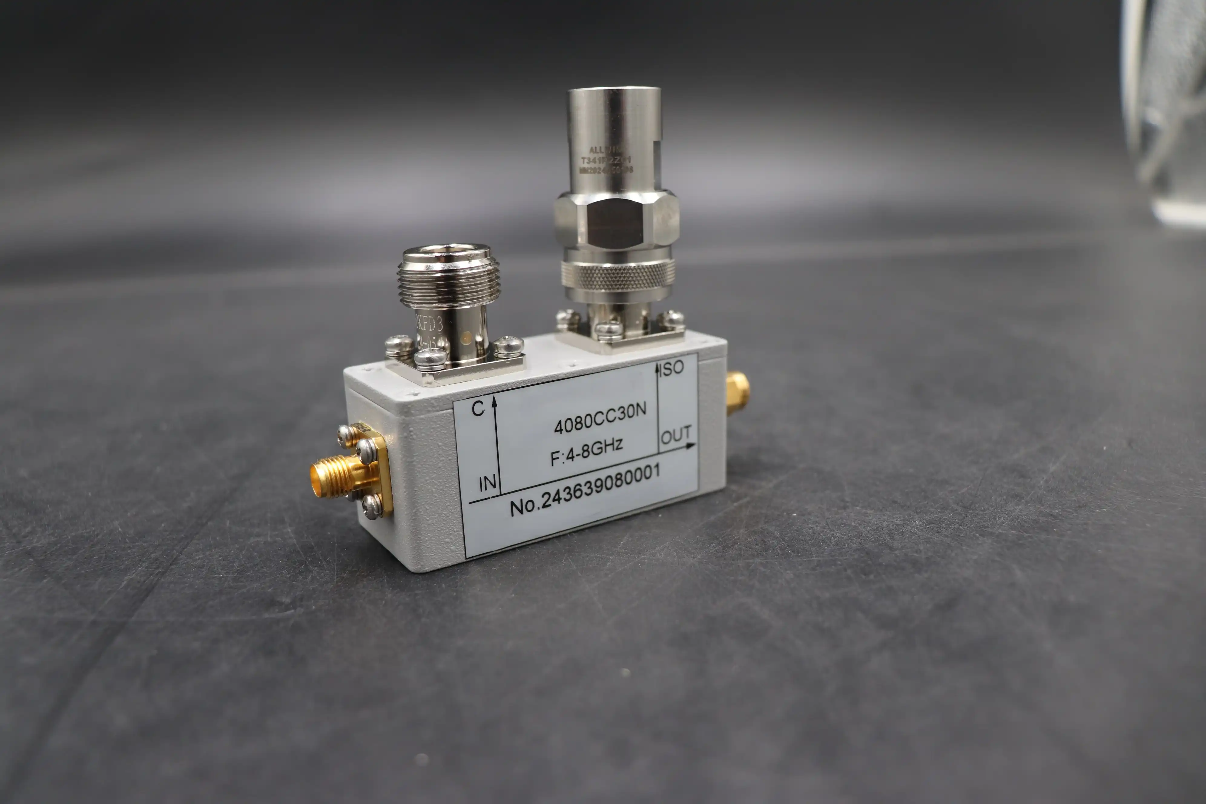
Also, when the dB value is high, it pulls less power from the main line. A 10 dB coupler costs about 0.46 dB to connect to the main path, and so does a 20 dB coupler. Look at the tolerances and how flat the whole band is, but give yourself some room for error.
Mistakes in Performance, Power, and Connectors
This is the part that tells you if the part will work in your system after the basics are set.
Mistake 4: Ignoring Directivity, Insertion Loss, and Return Loss
Don't just look at one number on the front of an RF coupler; look at the whole thing. It tells you how well the device separates waves that are moving forward and waves that are moving backward. To use dB, it's the same as IS - coupling. Low directivity can mess up VSWR readings, antenna tests, reflected-power alarms, and the safety of the amplifier. The reading is more off when the return loss you need to find is close to the forward direction of the coupler.
There is extra loss in the main path that isn't caused by coupling loss. This is called insertion loss. It weakens the signal and makes it less useful. The amount of return loss at each port shows how well the impedance matches. Things will be sent back to you by your system if the matching is bad.
You should get both average and guaranteed values for how well the signal is coupled, how much it loses or gains, how it directs, and how well it blocks out other signals. To fairly compare two quotes, ask the supplier to explain how the tests will be done.
Mistake 5: Underestimating RF Power Handling Capability
The power rates might be average, peak, pulsed, or continuous wave (CW). Multiply peak power by duty cycle to get average power. That is, a pulsed radar might stress a part in a much different manner than a CW source. What is safe to do depends on the pulse width, the repetition rate, and the temperature of the region. With the temperature dropping, most scores fall. In the engineering field, this is called derating.
Don’t simply look at the electricity stats. How heat is eliminated depends on what surface it is placed on, how air flows over it, and how it is made. The termination ratings are significant too, as the load on the isolated port does dissipate power.
Also, check out the link. One half of a coupler may be able to withstand a lot of power, while the SMA or N-type port may not. Know how it was manufactured, its breakdown protection, how long it was tested, and termination ratings for high power applications.
Mistake 6: Choosing the Wrong Port Configuration, Impedance, or Connector
First, choose out the building. A unidirectional coupler samples the wave in just one direction. It can sense both forward and backward waves; therefore, it may be utilised in protective circuits, antenna systems, and bi-directional networks.
Know your impedance before you place your purchase. Most RF and microwave systems employ 50-ohm; however, 75-ohm is used in certain broadcast and cable systems. So if you connect two 50 and 75 ohm parts together, you need roughly 14 dB of return loss.
Then check that the connector’s range, power, space, and sealing are right for your requirements. SMA can function up to 18 GHz, 2.92 mm up to 40 GHz and 2.4 mm up to 50 GHz. The N type can operate up to 11 GHz, although more accurate kinds can go up to 18 GHz. 7/16 DIN is excellent for high-power phone connections. And don’t forget to consider ease of maintenance, number of cycles the cables may be mated, and compatibility.
Mistakes in Comparison, Verification, and Sourcing
A well-written specification can fail if you don't compare parts properly or trust claims that haven't been proven. These three mistakes make things take longer and cost more.
Mistake 7: Comparing RF Couplers Without Considering the Complete System
The function is what should be used to compare. Power dividers divide the power between the ports. A lot of the time, hybrid couplers are used to blend or manage phases. You can change sampling and tell the difference between directions with directional couplers. This difference is hard to see if you only look at the unit price.
Making a procurement matrix for a coaxial directional coupler is what you should do instead. As part of the list, you should include the frequency range, coupling, directivity, insertion loss, return loss, power handling, connectors, lead time, test documentation, customization, warranty, and long-term supply. Decide how to rate each quote based on your needs.
This bigger picture lowers the costs of training and replacing people. Buying a part that costs less per unit but fails requalification or stops being made in the middle of your program will usually cost you more in the long run.
Mistake 8: Treating the Datasheet as Complete Without Verification Data
A datasheet only shows how well something works under the test conditions that are written down. If those things aren't true, the numbers might not match your production units. Make sure you look at the measurement tools, connectors, reference planes, frequency points, input power, temperature, and method of calibration.
Ask for test reports, S-parameter files, performance plots, serial number traceability, and compliance documents for OEM, infrastructure, or high-reliability programs that are specific to each person.
Next, make sure everything is okay by going through a technical review, testing the prototype, checking the incoming goods, judging the environment, doing a pilot run, and getting approval from the vendor. At each stage, the risk is different. Problems with electricity are seen in prototype tests, and the coupler's behavior can be seen when it is exposed to different temperatures or levels of vibration. Your schedule will stay safe if you do these things before you buy in bulk.
Mistake 9: Selecting a Supplier Without Evaluating Manufacturing Capability
A lot of the time, distributors make it simple to get simple parts quickly. Most of the time, manufacturers and OEM specialists can help with engineering support, customization, and making sure that production is always the same. Pick the type of provider that works best for you.
Check how well it covers both wideband and narrowband designs, as well as coupling options, impedance, connector interfaces, high-power construction, custom housings, prototype support, batch consistency, and the ability to put your own label on the product. Then, find out about the guaranteed specs, S-parameters, temperature derating, minimum order quantities, lead times, support for repeat orders, warranty, and how long the product will be available.
It's also important to be able to measure things. Any supplier with test tools on site can look over parts before they are sent out. For instance, ADM has labs with microwave measuring tools that can work up to 110 GHz. They are also ISO 9001 certified and sell RoHS-compliant goods.
A Checklist and Selection Guide for Your Specification
Now I'll make the things I said earlier into desk tools for you.
A Practical Specification Checklist for Coaxial Directional Couplers
Use this list before you ask for quotes or sign off on samples. The needs are split into three groups.
- Electrical: State the application, frequency range, impedance, coupling value, coupling flatness, directivity, insertion loss, return loss, and isolation. Add phase response if your system depends on it. Include the tolerance you accept for each value, because a requirement without a tolerance leaves suppliers guessing.
- Power and reliability: List continuous and pulsed ratings, duty cycle, operating temperature, thermal management, connector power limits, sealing, and expected service life. Describe how you will mount and cool the coupler, since the same part can perform differently on a heat-sinking plate than in open air.
- Mechanical and purchasing: Specify connector type and gender, dimensions, mounting method, packaging, and inspection criteria. Request test reports and define sample approval steps. Add lead time, minimum order quantity, and warranty terms, so the quote you receive matches the delivery your program needs.
With a full checklist, suppliers can give more accurate quotes, and there is less back-and-forth, which speeds up the approval process for samples.
How to Choose the Best Coaxial Directional Coupler for Your Application
Pick the correct coaxial directional coupler for the job. Broadband test systems need to be able to connect to a lot of different devices, be stable, have low insertion loss, and have interfaces that are simple to change. In order for the upper band to be useful in microwave applications, it needs to work properly, have low parasitics, accurate mechanics, and stable amplitude and phase.
It's important for high-power transmitters to be able to handle heat, have low main-line loss, have tough connectors, and be able to check for reverse power. The frequency bands, coupling values, housings, and connectors that OEM programs may need may be unique. They may also need production that can be done over and over again.
An important thing that buyers in defense and aerospace often add to this list is compliance and traceability documents. On the other hand, research labs need a quick prototype more than anything else. Electrical, mechanical, temperature, safety, lifecycle, and supply chain needs should all be taken into account when making the final choice. If the electrical goals can be met by two different options, choose the one with better test data and a clearer supply plan.
How ADM Supports Coaxial Directional Coupler Programs
ADM has been making microwave goods for more than 20 years, ever since it started in the 2000s. Some of the things we make are waveguide assemblies, coaxial and cable assemblies, microwave antennas, feeds, and servos. We also make antenna measurement systems and microwave measurement equipment. Our goods are used for defense, navigation, satellite communications, and trips into space.
Since we offer OEM services like quick turnaround, technical support, and prototyping, you can try us out before you buy a lot of them. We also have a microwave darkroom that is 24 m long and can test from 0.5 GHz to 110 GHz. This helps us with our work with antennas and measuring things. Our engineers can look at what you need in terms of power, direction, coupling, and connectors and suggest a setup that will work well.
Conclusion
When calling for a coaxial directional coupler, teams make a mistake when they don't follow the basics. Start by making sure everyone knows what the application is. Then there needs to be a full operating band and a coupling factor that matches the band gaps between the instrument and the mains power. Directivity, insertion loss, and return loss are the three things that need to be looked at together. When power ratings are made, they also need to take pulsed conditions, temperature, and connector limits into account. You need to make sure of the impedance, port configuration, and connectors before you place your order. If you compare couplers based on how they work with power dividers and hybrid couplers, ask for test conditions and S-parameters, and see how well a supplier can make things, you can lower the risk of having to redesign them. A specification that includes the mechanical, electrical, thermal, and supply-chain picture can help avoid wrong measurements, too much heat, and delays in integration.
FAQ
Q1: What is a coaxial directional coupler?
It's a passive RF device that only lets power flow in one direction along a transmission line. For power to flow in the other direction, it blocks it.
Q2: What is the difference between 10 dB and 20 dB coupling?
It takes about 10% of the power coming in for a 10 dB coupler to work, and 1% for a 20 dB coupler. Choose based on how much power the instruments and the wall can handle.
Q3: When do I need a dual-directional coupler?
There is a need for one when you need to check both forward and backward power at the same time, like in antenna systems or protection circuits.
Q4: Is a broadband coupler always better?
Not at all. Coupling can become less flat or direct when the coverage is wider. A narrowband unit might work better for a single band.
Request a Coaxial Directional Coupler Recommendation or Quote from ADM
We will look over your needs after you send them to ADM. As well as the frequency, coupling factor, main-line power, directivity, impedance, connector type, quantity, and delivery date, please let us know. If you need to buy coaxial directional couplers, our company can help you with anything from a small order to a large one. We offer OEM services, prototyping, fast turnaround, and strict quality control. You can email craig@admicrowave.com to learn more.
References
1. Microwave Engineering, 4th Edition, Wiley, 2011.
2. RF and Microwave Coupled-Line Circuits, 2nd Edition, Artech House, 2007.
3. Passive RF and Microwave Integrated Circuits, Elsevier, 2004.
4. Fundamentals of Vector Network Analysis, Rohde & Schwarz, 2008.
5. Foundations for Microwave Engineering, 2nd Edition, Wiley-IEEE Press, 2001.
6. Microwave and RF Design: A Systems Approach, SciTech Publishing, 2010.
YOU MAY LIKE
 VIEW MOREIndustrial Microwave Sliding Short
 VIEW MOREEnd Launch Double Ridged WG To Coaxial Adapter
 VIEW MOREDouble Ridge Waveguide Termination
 VIEW MOREWaveguide Unmatched Termination
 VIEW MOREBroadwall Directional Coupler
 VIEW MOREHigh Power Waveguide Isolator
 VIEW MOREHigh Power Coaxial Switch
 VIEW MOREPoint Focusing Horn Lens Antenna