




Average vs Peak Power: Rating a High Power Waveguide Isolator Correctly
The right way to rate a high power waveguide isolator is to check both the average power and the peak power separately, and then confirm both of them in real-world use. The heat load on the ferrite, the termination, and the waveguide walls is set by the average power. An electric field can arc and break down during a pulse if the peak power is too high. Even if a low-duty radar passes the thermal test, it may still fail the peak voltage test. Even if the peak check goes well, a high-duty system can still get too hot. I'll show you how to find values and compare datasheets fairly in this article.
Why One Power Number Does Not Describe an Isolator
Average Power: The Thermal Limit
The isolator can handle a certain amount of RF energy over time. This is called its average power. Insertion loss turns some of that energy into heat, and the isolator adds to that by absorbing any reverse energy. The element that is sensitive is the ferrite. As the temperature goes up, its magnetic properties change, and a ferrite that goes above its Curie temperature stops acting in a way that isn't reciprocal. The center frequency moves and isolation gets weaker when heat is present. This is why an average power rating depends on the temperature, the way the device is cooled, and the power that is reflected. When a supplier gives you a wattage number, make sure you know what conditions apply. A number taken on a cool bench with a load that is the same on both sides doesn't tell you much about a hot rack of equipment.
Peak Power: The Breakdown Limit
Peak power is the amount of power that is available at any given time during a pulse. It changes the strength of the electric field inside the waveguide. The field strength determines whether air or a dielectric breaks down. In a matter of microseconds, an arc can damage ferrite, make metal surfaces pit, and trip a transmitter. This is about air pressure. As pressure drops, the breaking point goes down. This means that a unit at high altitude has less margin than the same unit at sea level. Putting dry gas, like nitrogen, under pressure on the waveguide makes that margin bigger. Because the standing wave adds to the forward wave at voltage peaks, reflected power also makes the local field stronger. Because of this, a mismatch can make fields go above the forward-only value.
Why Transmitter Output Alone Misleads
A lot of people choose a high power waveguide isolator based on the transmitter's rated output and stop there. That shortcut doesn't look at the things that can damage parts, like an antenna that doesn't match, a loose flange, ice on a radome, or a load that changes while processing. The isolator has to take in the extra power that is reflected by each fault. Make a short list of the following things before you ask for a quote: frequency, waveguide size, operating mode, pulse width and repetition rate, worst-case reflected power, cooling method, flange type, and documentation needs. Include any specifics that need to be changed, like a different material or mounting layout. A full checklist lets the supplier compare the rating to your real duty instead of just a number.
How a High Power Waveguide Isolator Handles Power Stress
Non-Reciprocal Operation in Brief
A waveguide isolator is a passive two-port device. It places ferrite material in a waveguide segment and provides it with a permanent magnetic bias. The bias alters the ferrite’s interaction with waves travelling in opposite directions. Scientists outlined this ferromagnetic Faraday effect in the early 1950s. Later engineers utilised it in junction circulators. Energy loss in the forward direction is small. When reverse energy meets anything that can take it in, it transforms to heat. This behaviour makes magnetrons, klystrons, travelling wave tubes, and solid-state power amplifiers impervious to reflections due to antenna or load mismatch. Reverse power handling is a rating in its own right, as the reverse route finishes in an absorber. Make sure to request it specifically.
Where Heat and Voltage Stress Build Up
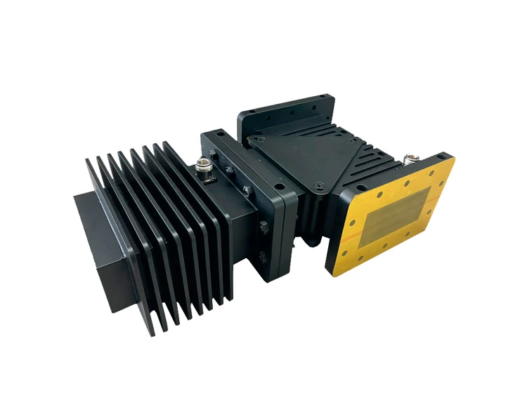
Stress is strong in a few areas. The field and heat are carried by the ferrite and the spacers that separate it from the magnet. The absorber is frequently the hottest with power running in reverse. Any sharp edges, any gaps where flanges connect, and any debris on the surface all tend to concentrate the electric field and make arcing more probable. Thermal cycling over time may modify the mechanical tolerances, the VSWR, and the isolation. Metal becomes larger as it gets heated. Surface conditions vary with humidity and dust, and the breakdown threshold decreases with increasing altitude. Design for cooling is as vital as design for electricity. Lower-power units have air cooling using fins. For reflective loads of several kilowatts, liquid cooling is typically required to keep the ferrite below its Curie temperature. Ask the provider not just what the overall rating is, but also where the issue areas are.
Isolator or Circulator?
A circulator is a three-port device that circulates electricity from port to port. An isolator is similar to a circulator; only the third port is terminated in a matched load so it absorbs the reverse energy instead of routing it elsewhere. If your system wants the signal mirrored at a separate port, best to utilise a circulator. If all you want to do is safeguard the source, then a simple solution is an isolator. That figure is just as significant as forward power. The load inside an isolator affects how much reverse power may be tolerated. Some systems use a combination of a circulator and an outside high-power load when reflected power is too much for an integrated absorber. Compare the two architectures before you sign off on the specification.
How to Calculate the Required Power Rating
The Duty-Cycle Formula with a Worked Example
When it comes to pulsed systems, duty cycle is equal to pulse width times pulse repetition frequency. Peak power times duty cycle equals average power. Take a pulse of 100 kW that lasts 10 μs at 1 kHz. The duty cycle is 10 µs times 1,000 Hz, which is 0.01, or 1%. One kW is equal to 100 kW times 0.01. Even though the isolator only sees 1 kW of heat on average, it has to handle 100 kW of heat every pulse. This is the main reason why a single rating can be wrong. A lot of radar sources, like Skolnik's books, talk about peak power, average power, and duty cycle as if they were three separate but connected numbers. Check each one against the datasheet.
CW, Pulsed, and Modulated Systems
The ferrite, absorber, and waveguide walls of a high power waveguide isolator get hot all the time in continuous-wave systems, so average power, cooling, and long-term stability are the most important things to look at. In pulsed radar and accelerator systems, the average power may be low, but the peak voltage may be high. This means that pulse width, repetition rate, and breakdown margin are more important. Extra care needs to be taken with modulated, burst, and variable-duty systems. When there are short breaks between bursts, the part doesn't have much time to cool down, so the heat can build up faster than a simple duty-cycle estimate would suggest. When you can, give your supplier the waveform itself instead of just a number. A timing diagram or oscilloscope capture takes away the need to guess, which leads to a more accurate rating.
Reflected Power, VSWR, and Derating
Forward power isn't the whole story. The isolator has to take in that power without getting too hot, and worst-case VSWR tells us how much power goes back to the source. A VSWR of 2:1 gives back about 11% of the forward power, and a VSWR of 3:1 gives back 25%. Along with normal operation, list fault conditions like an open or shorted antenna line. Then, use the supplier's suggested derating for cooling, temperature, and altitude. If your cabinet gets too hot or your site is very high up, the usable rating drops below the value written on the plate. The rated number should be written in your specification so that both the purchasing and engineering teams can use the same number.
Comparing Performance Beyond the Power Rating
Insertion Loss Turns into Heat
Even though insertion loss seems small on paper, it turns RF energy into heat inside the device. About 450 W of heat is generated by 0.2 dB of loss at 10 kW input. The math behind ADM's stated average insertion loss of 0.3 dB is the same. The device turns about 67 W of forward power into heat at the maximum forward power of 1,000 W. That number is based on a calculation of the average value, not a real measurement, so check it against your frequency and temperature. When insertion loss is low, self-heating is low, and more power gets to the antenna. When you compare quotes, you should look at the loss at the same power level, frequency, and temperature.
Isolation, VSWR, and Frequency Span
The amount of reverse energy that the device blocks is shown by isolation. Most values in a datasheet start around 20 dB and go up as the number of junctions goes up. Make sure that the isolation works across all frequencies, all temperatures, and with real-world reflected power, not just in a low-power test at room temperature. The same way to compare VSWR and return loss. Waveguide size is also important. (X-band) WR-90 works at 8.2 to 12.4 GHz, and (S-band) WR-284 works at 2.60 to 3.95 GHz [1]. Size doesn't tell you how much power a unit can hold because ferrite, absorber, and cooling designs can be different in two units of the same size. Ask for test data that is specific to frequency.
Common Rating Mistakes
This happens five times over and over again. If you only use one power figure, like average or peak, you'll make a mistake. The second doesn't take into account reflected energy. The third way is to look at datasheets that were tested at various temperatures or while being cooled. The fourth is thinking that a low duty cycle takes away the risk of breakdown. There is still full peak voltage in each pulse, so it doesn't. It costs the most to choose the cheapest part without checking those conditions. A broken source, downtime, requalification, and an emergency replacement can add up to a lot more than the difference in price. When you compare like with like, write down the test conditions next to each number you get.

Selecting and Verifying a High Power Waveguide Isolator
Match the Design to the Application
Start with your job. The thermal capacity, cooling, and long-term stability of a high power waveguide isolator in a CW microwave heating or plasma system are the most important things. Peak-power handling, pulse endurance, and breakdown margin are the first things that a radar or defense transmitter looks at. When an OEM system runs CW tests, pulsed modes, and different power levels in a cabinet with little airflow, it needs to be checked for worst-case temperatures, and every mode change must be confirmed. Environmental qualification, traceability, and lifecycle supply are all added to aerospace projects. Make a weighted specification that includes things like power ratings, the ability to reverse the power, insertion loss, isolation, VSWR, cooling, interfaces, and delivery support. In some situations, a custom isolator may work better than a part from a catalog.
What to Verify Before Purchase
Ask for a full datasheet that lists the frequency, waveguide model, average and peak ratings, pulse conditions, reverse-power limits, insertion loss, isolation, VSWR, temperature range, and cooling needs. Check to see if each value is normal, guaranteed, calculated, or measured on the exact model used for production. Look at the mechanical drawing to see what kind of flange it has, how it is mounted, how big it is, how much it weighs, and how the surface is finished. Then, ask for CAD files. Then look at the business side, including prototype support, production capacity, export paperwork, packaging, inspection, warranty, lead time, and engineering help after the sale. Full-power aging, vector network analyzer measurements of S-parameters, thermal cycling, and leakage testing for pressurized waveguides are common ways to check the quality of these parts.
ADM Waveguide Isolator Specifications and OEM Support
We have waveguide isolators at ADM that come in different sizes and frequency bands for use in test and measurement systems and feeder systems. The typical specs include 20 dB of isolation, 0.3 dB of insertion loss, an operating band of 800 MHz, and a maximum forward power of 1,000 W. The housing is made of copper and aluminum, and the temperature range for normal use is -40 to +70 °C. At the design stage, we look at cost, reliability, and how easy it is to make. This keeps costs low and delivery quick. In the catalog, it says "forward power." Could you send us your peak power and pulse data so we can look it over? Customization, quick prototypes, and engineering support are all part of our OEM service for different frequency ranges, sizes, or materials. We can measure up to 110 GHz in our labs, and all of our products are ISO 9001 certified and RoHS compliant.
Conclusion
To be safe, a high power waveguide isolator needs to be checked for power twice. It is the average power that causes the ferrite, absorber, and waveguide walls to get hot. Peak power, on the other hand, causes electric field stress and the risk of breakdown. Pulsed systems need 100 kW of peak power even though they only use 1 kW of average power. This is shown by the 100 kW example. The useful rating can be changed by things like altitude, worst-case VSWR, reflected power, and cooling. Also, insertion loss adds heat. It is important to compare isolation, frequency span, and waveguide size under the same test conditions. The real job of the system should guide the selection process, and full datasheets, stated test conditions, and drawings should be used for verification. This kind of rating is based on actual operating and fault conditions, not just one number.
FAQ
Q1: What is the difference between average power and peak power in a high power waveguide isolator?
This is how the ferrite and absorber are limited by average power, which measures the heat load over time. Peak power is the highest level that can be measured at any given time during a pulse. It also limits the breakdown margin. You need to check both ratings.
Q2: How do I calculate average power for a pulsed system?
To find the duty cycle, multiply the pulse width by the frequency of repetition. Then, take the peak power and multiply it by the duty cycle. A 100 kW pulse that lasts 10 microseconds and is set at 1 kHz has a 1% duty cycle and an average power of 1 kW.
Q3: Why does insertion loss matter at high power?
Since there is insertion loss, RF energy is turned into heat inside the device. About 450 W is lost for every 10 kW of power. Less self-heating and more power at the antenna means less loss.
Q4: What should I send for an accurate quotation?
Send frequency, waveguide size, peak and average power, pulse width, repetition rate, worst-case reflected power, cooling method, flange type, and temperature range; all should be specified. It also helps to draw.
Request a High Power Waveguide Isolator Quote from ADM
ADM can be reached at craig@admicrowave.com with information about your frequency, waveguide size, peak power, duty cycle, and reflected power. We make high power waveguide isolators and have been making them for over 20 years. We offer low prices, fast delivery, OEM customization, and engineering support. Our team will look over your ratings and get back to you with a suggestion, a price, and a lead time.
References
1. Microwave Engineering, 4th Edition, David M. Pozar, Wiley, 2011
2. Radar Handbook, 3rd Edition, Merrill I. Skolnik, McGraw-Hill, 2008
3. Introduction to Radar Systems, 3rd Edition, Merrill I. Skolnik, McGraw-Hill, 2001
4. Operation of the Ferrite Junction Circulator, C. E. Fay and R. L. Comstock, IEEE Transactions on Microwave Theory and Techniques, 1965
5. The Ferromagnetic Faraday Effect at Microwave Frequencies and Its Applications, C. L. Hogan, Bell System Technical Journal, 1952
6. Microwave Ferrites and Ferrimagnetics, Benjamin Lax and Kenneth J. Button, McGraw-Hill, 1962